UR7HCTS2-USB Ultimate USB ScreenCoder® data sheet
UR7HCTS2-USB
Ultimate USB ScreenCoder®
4/5/8-Wire USB Touch Screen Encoder
Semtech and ScreenCoder are registered
trademarks of Semtech Corporation. All other
trademarks belong to their respective owners.
Copyright ©2000-2002 Semtech Corporation
UR7HCTS2-USB data sheet v1.06 2002-12
www.semtech.com
1
HID & SYSTEM MANAGEMENT PRODUCTS, SCREENCODER® FAMILY
DESCRIPTION
FEATURES
· Handheld PCs (H/PCs)
· Notebook PCs
· Portable devices
· Interactive kiosks
· Industrial/custom touch screens
The UR7HCTS2-USB Ultimate USB
ScreenCoder® is the first single IC
that seamlessly interfaces ANY 4-
wire, 5-wire, or 8-wire resistive
touch screen to a USB-equipped
system. It is also the first touch
screen controller IC on the market
designed to accommodate a very
wide range of size, capacitance
and resistance of touch screens,
providing a universal performance
solution among different OEM
products and touch screen
vendors. This unique feature of
the IC provides OEMs with a wide
variety of interchangeable touch
screen options.
Unlike implementations with
separate digitizers, the
UR7HCTS2-USB integrates a
digitizer with a controller that
performs all touch detection, noise
filtering, error elimination and
provides the host with processed
and stable positioning data over
USB. Semtech's unique motion
algorithms provide high resistance
to RF and other noise sources
resulting in precise, jitter-free
cursor control.
Ideal applications for the
UR7HCTS2-USB include portable
devices, interactive kiosks and
industrial / custom displays with
integrated touch screens.
The universal features of the
UR7HCTS2-USB, as implemented
in both the system and the sensor
interface, reduce the development
effort and cost of touch input
based systems. The UR7HCTS2-
USB is available in a 36-pin SSOP
package.
· Highly resistant to RF and other
noise
· No digitizer or external A/D
necessary
· Fully compliant with USB HID
absolute-mode pointing device
specifications
· Free driver with calibration applet
available for Windows® 98 SE,
Windows® Me, Windows® 2000,
and Windows® XP
· Uses 36-pin SSOP package
· Controller & digitizer in a single IC
· Interfaces the system via USB
· Works with ANY 4-, 5-, or 8-wire
resistive touch screen regardless
of size, material or vendor
· Provides high resolution: 1000
points per axis, enabling IC to
make precise drawing and
signature captures
· Accurate, quick touch response
due to Semtech's advanced
sampling technology and
algorithms
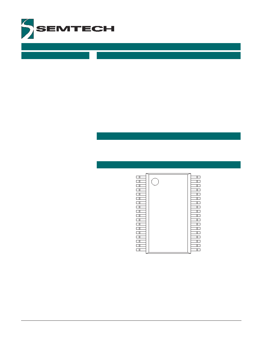
1
18
19
36
N/C
N/C
N/C
SXL/NW_AD
SYT/NE_AD
SYB/SW_AD
SXR/SE_AD
SENSE_DRV
SENSE_AD
N/C
N/C
VREF
_RESET
VSS2
VDD
OSCIN
_OSCOUT
VSS
D+
D-
_RB
_TOUCH
XR2/SE2
YB2/SW2
YT2/NE2
XL2/NW2
N/C
N/C
USBV
N/C
N/C
_WR5/WR4-8
XL1/NW1
YT1/NE1
YB1/SW1
XR1/SE1
36-pin SSOP
APPLICATIONS
PIN ASSIGNMENTS
PRELIMINARY
ORDERING CODE
Copyright ©2000-2002 Semtech Corporation
UR7HCTS2-USB data sheet v1.06 2002-12
www.semtech.com
2
Package Options
Pitch
TA = -20° C to +85° C
36-pin plastic SSOP
0.8 mm
UR7HCTS2-USB-DR
Other Materials
Type
Order number
ScreenCoder® USB eval. kit
Evaluation kit
EVK7-TS2-USB
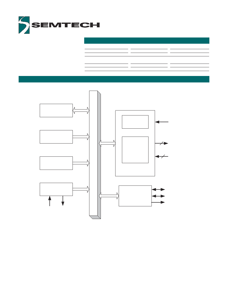
Power
Management
Section
Power -On Reset
16-Bit Timer
Oscillator Circuit
Sensor Interface
Switch Interface
Touch Panel
Interface
USB
Communication
Interface
OSCIN
_OSCOUT
Drivers for Touch
Screen
4
D+
D-
Right Button
USBV
Sense Line(s)
BLOCK DIAGRAM FOR THE UR7HCTS2-USB
FUNCTIONAL DESCRIPTION
PIN DEFINITIONS
Copyright ©2000-2002 Semtech Corporation
UR7HCTS2-USB data sheet v1.06 2002-12
www.semtech.com
3
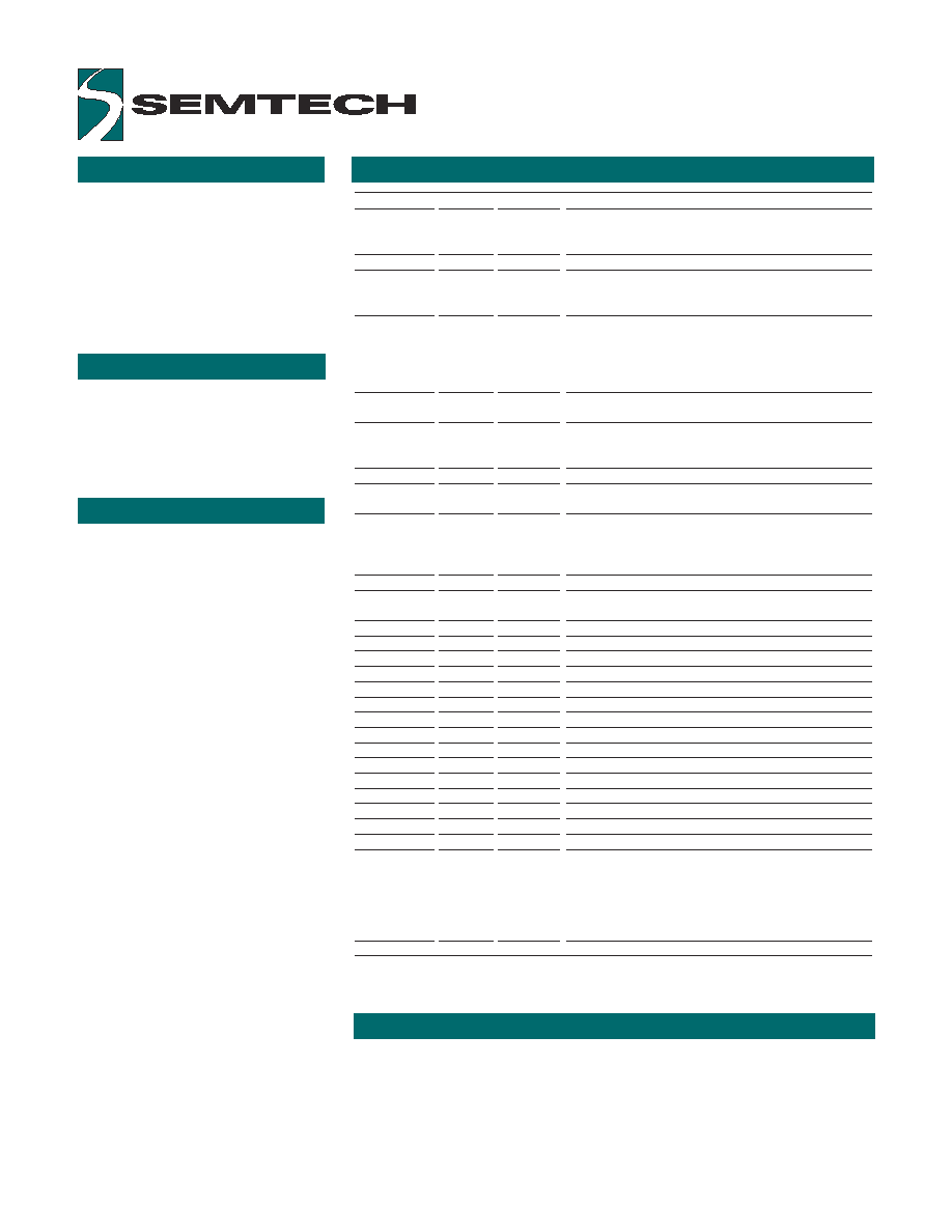
Mnemonic
Pin #
Type
Name and Function
Power
VDD
15
P
Power supply
VSS, VSS2
18, 14
P
Ground
Reset
_RESET
13
I
Reset: apply 0V to provide orderly start-up
Oscillator
_OSCOUT
17
O
Oscillator output: open for external clock input or
other side of the ceramic resonator with built-in load
capacitors
OSCIN
16
I
Oscillator input: external clock input or one side of the
ceramic resonator with built-in load capacitors
USB
D-
35
I/O
USB D- Line
D+
36
I/O
USB D+ Line
USBV
26
O
USB reference voltage output: output pin for pulling
up a D- line with a 1.5K Ohm external resistor
Touch
screen
_RB
34
I/O (nd)
Right button: active low, strobed sampling
_TOUCH
33
I/O
5-wire: Touch Detection
_WR5/WR4-8
23
I/O
4/8-wire: Leave open (has internal pull-up);
5-wire: Tie to ground
SENSE_AD
9
AI
5-wire: Sense A/D
SENSE_DRV
8
I/O
5-wire: Sense drive
SXL/NW_AD
4
AI
4/8-wire: Sense line for X Left. 5-wire: Northwest
SXR/SE_AD
7
AI
4/8-wire: Sense line for X Right. 5-wire: Southeast
SYB/SW_AD
6
AI
4/8-wire: Sense line for Y Bottom. 5-wire: Southwest
SYT/NE_AD
5
AI
4/8-wire: Sense line for Y Top. 5-wire: Northeast
VREF
12
AI
Reference voltage for built-in A/D
XL1/NW1
22
I/O
4/8-wire: Sense drive X Left. 5-wire: Northwest
XL2/NW2
29
I/O
4/8-wire: Sense drive X Left. 5-wire: Northwest
XR1/SE1
19
I/O
4/8-wire: Sense drive X Right. 5-wire: Southeast
XR2/SE2
32
I/O
4/8-wire: Sense drive X Right. 5-wire: Southeast
YB1/SW1
20
I/O
4/8-wire: Sense drive Y Bottom. 5-wire: Southwest
YB2/SW2
31
I/O
4/8-wire: Sense drive Y Bottom. 5-wire: Southwest
YT1/NE1
21
I/O
4/8-wire: Sense drive Y Top. 5-wire: Northeast
YT2/NE2
30
I/O
4/8-wire: Sense drive Y Top. 5-wire: Northeast
Reserved
N/C
1-3,
Reserved
10, 11,
24, 25,
27, 28
Note: An underscore before a pin mnemonic denotes an active low signal.
Pin Types Legend: I=Input; O=Output; I/O=Input or Output; P=Power; Al= Analog Input;
I/O (nd) open drain
The UR7HCTS2-USB consists
functionally of five major sections
(see the Functional Diagram on
Page 2). These are the Sensor
Interface, the Power Management
Section, the 16-Bit Timer, the
Oscillator Circuit and the USB
Interface.
The UR7HCTS2-USB is a low-speed USB device with remote wake-up
capability. The IC asks the system to send report requests every 10ms
according to the USB specification for a low speed device.
The UR7HCTS2-USB describes itself as a pointer, and provides absolute
position data to the system.
This IC has a built-in oscillator
circuit capable of operations with
an external 6.00 MHz clock source,
such as a ceramic resonator with
built-in load capacitors.
OSCILLATOR
According to the USB
specification, if there is no activity
of the USB port for 3 ms, the
system is considered to be in a
suspended state.
The UR7HCTS2-USB, on detecting
that the system is in suspend,
checks the state of the touch
screen and the right button. If
there is no touch pressure
detected and no button pressed,
the UR7HCTS2-USB enters the
suspended state. In suspend, the
IC fully complies with the USB
specification for power
consumption, dissipating current
only in the USB-mandated pull-up
for device identification.
The IC supports remote wake-up to
conserve power. If the system
relies on the device to perform
wake-up, the IC sends a resume
message to the system when there
is activity on the touch screen or
button.
If the system does not allow
remote wake-up, the
UR7HCTS2-USB does not send
resume messages to the system
when it is awakened by activity on
the touch screen or button.
POWER MANAGEMENT
USB FUNCTIONALITY

TOUCH SCREEN SENSOR INTERFACE
Copyright ©2000-2002 Semtech Corporation
UR7HCTS2-USB data sheet v1.06 2002-12
www.semtech.com
4
The UR7HCTS2-USB can acquire data from any 4-wire, 5-wire, or 8-wire resistive touch screen sensors. The
sensor interface has the following features:
Touch detection
The IC periodically checks touch pressure applied to the panel. If there is no touch, the IC does not perform
measurements and does not send data to system. When touch pressure is detected, the IC further qualifies and
determines the amount of pressure. Semtech's proprietary, patent-pending touch detection algorithm performs this
test very quickly, accommodating sensors with various plate-to-plate capacitances.
Touch Measurement (4/8-wire sensors)
Position information is only collected if it has been determined that the touch pressure is sufficient for an accurate
reading. To obtain position information from the resistive touch screen sensor, the UR7HCTS2-USB uses four
internal drivers (two pins for each driver) and four sense lines. During sampling, the drivers of the X-axis are
activated by setting one X-drive high and the other X-drive low. The drivers for Y-axis are set floating. This action
produces a voltage gradient across the touch screen's surface in the X direction. The internal A/D measures both
the voltage across the activated X-plane and the voltage potential between the planes. Next, the drivers for the Y-
axis are activated while the drivers for X-axis are set floating. Again, the internal A/D measures both voltage across
the activated plane and potential between the planes. The X and Y absolute position is obtained from these four
A/D measurements. The IC keeps measuring the touch pressure even while the positioning data is acquired. If
insufficient touch pressure is detected during sampling of the position, the current data set is rejected.
Touch Measurement (5-wire sensors)
Position information is collected only if the touch pressure is sufficient for an accurate reading. The 5-wire touch
screen has two panels. One is the resistive panel for supplying the voltage gradient. The other is the conductive
panel used to get the touch voltage. To obtain position information from the resistive touch screen sensor, the
UR7HCTS2-USB uses four internal drivers (three pins for each driver) and one sense line. During sampling, the
drivers of the X-axis are activated by setting one X-drive high and the other X-drive low. The sense plane is set
floating. This action produces a voltage gradient across the touch screen's surface in the X direction.
The internal A/D measures both the voltage across the activated X-plane and the voltage potential between the
planes. Next, the drivers for the Y-axis are activated. Again, the internal A/D measures both voltage across the
activated plane and potential between the planes. The X and Y absolute position is obtained from these A/D
measurements.
Touch algorithm
Due to vibration and electrical noise, the raw data can not be used directly. Internal data processing delivers
consistent position accuracy and quick touch response.
Resolution
The UR7HCTS2-USB uses a built-in A/D converter to get the touch position. The maximum touch screen resolution
is 1000 points per axis. Resolution varies somewhat for different touch screen sensors, due to voltage droop on
connecting wires.
Touch screens from different makers
Operating parameters for the touch screens from different manufacturers vary depending on the size of the sensor,
material it is made from, and mechanical construction. The UR7HCTS2-USB takes these properties into account,
and adjusts automatically for plate-to-plate capacitance, intrinsic plate resistances, etc.
Buttons
The UR7HCTS2-USB implements the equivalent of left and right mouse buttons. Left button press is reported when
there is touch pressure on the panel, and then released when the pressure stops. The right button is implemented
as a switch using pin 34.
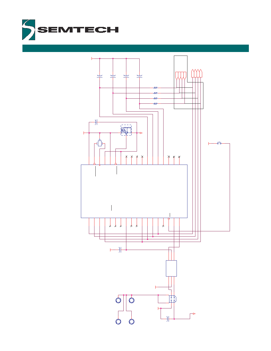
SAMPLE SCHEMATIC WITH 4/8-WIRE SENSOR
Copyright ©2000-2002 Semtech Corporation
UR7HCTS2-USB data sheet v1.06 2002-12
www.semtech.com
5
SY
B
YT
SYT
YB
XL
XR
SX
L
SXR
DRV
_
Y
B
S
E
N
SE_YB
SENSE_XL
DRV_XL
SENSE_XR
DRV_X
R
DRV_YT
SENSE_YT
GND
GND
VDD
GND
GND
GND
VDD
GND
SHIELD
Mounting holes
See Notes
Notes:
UR7HCTS2-USB is hardware compatible with the UR7HCTS2-U860.
Customers using the UR7HCTS2-U860 can use their existing design.
Connect drive and sense lines together for the 4-wire sensor.
Y1 == 6.00 MHz ceramic resonator with built-in load capacitors:
AVX PBRC-6.00BR or Murata CSTC6.00MG or equivalent.
STF203-33 is a USB upstream port filter and protection chip.
C1
0.1u
F
SW1
RIGHT BUTT
O
N
C5
10
n
F
+/-10% X7R
U
3
STF203-33
DI/O
1
GND
2
DI/O
3
DI/O
4
VBUS
5
DI/O
6
U2
T
C
5
4
V
C
4502ECB
1
2
3
J1
1
2
3
4
5
6
C3
10
n
F
+/-10% X7R
Y1
6.00MHz
U1
3
6
Pin DR
N/C
1
N/C
2
N/C
3
SXL
4
SYT
5
SYB
6
SXR
7
RVSD4
8
RVSD5
9
RVSD6
10
RVSD7
11
VREF
12
RESET
13
VSS2
14
VDD
15
OSCIN
16
OSCOUT
17
VSS
18
D+
36
D-
35
RB
34
N/C
33
XR2
32
YB2
31
YT2
30
XL2
29
N/C
28
N/C
27
USBV
26
N/C
25
N/C
24
WR5/WR4
23
XL1
22
YT1
21
YB1
20
XR1
19
C6
10
n
F
+/-10% X7R
C7
0.1u
F
RN1
4.7K
1
3
5
7
8
6
4
2
C2
1
0uF
C4
10
n
F
+/-10% X7R
UR7HCTS2-USB