 | –≠–ª–µ–∫—Ç—Ä–æ–Ω–Ω—ã–π –∫–æ–º–ø–æ–Ω–µ–Ω—Ç: SG6932 | –°–∫–∞—á–∞—Ç—å:  PDF PDF  ZIP ZIP |
Product Specification
Green mode PFC/Forward PWM Controller
SG6932
©System General Corp.
- 1 -
www.sg.com.tw
Version 1.0(IAO33.0011.B1) Feb.24, 2006
FEATURES OVERVIEW
Interleaved PFC/PWM switching
Green mode PFC and PWM operation
Low operating current
Innovative Switching-Charge
multiplier-divider
Multi-vector control for improved PFC output
transient response
Average-current-mode for input-current shaping
PFC over-voltage and under-voltage protections
PFC and PWM feedback open-loop protection
Cycle-by-cycle current limiting for PFC/PWM
Slope compensation for PWM
Selectable PWM maximum duty cycle 50% and 65%
Brownout protection
Power on sequence control and soft-start
APPLICATIONS
Switch mode Power Suppliers with Active PFC
Servo System Power Supplies
PC-ATX Power Supplies
DESCRIPTION
The highly integrated SG6932 is specially designed
for power supplies consist of boost PFC and Forward
PWM. It requires very few external components to
achieve green-mode operation and versatile
protections/compensation. It is available in 16-pin DIP
and SO packages.
The patented interleave-switching feature
synchronizes the PFC and PWM stages and reduces
switching noise. At light load, the switching frequency is
continuously decreased to reduce power consumption.
For PFC stage, the proprietary multi-vector control
scheme provides a fast transient response in a
low-bandwidth PFC loop, in which the overshoot and
undershoot of the PFC voltage are clamped. If the
feedback loop is broken, SG6932 will shut off to prevent
extra-high voltage on output.
For the Forward PWM stage, the synchronized
slope compensation ensures the stability of the current
loop under continuous-conduction-mode operation.
Hiccup operation during output overloading is guaranteed.
The soft start and programmable maximum duty cycle
ensure safe operation.
In addition, SG6932 provides complete protection
functions such as brownout protection and RI open/short
latch off.
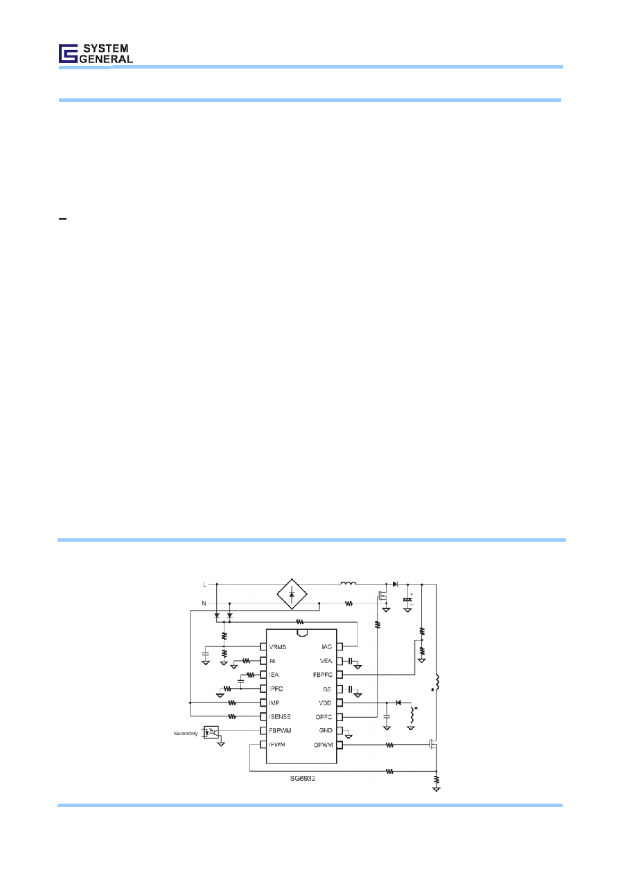
TYPICAL APPLICATION

Product Specification
Green mode PFC/Forward PWM Controller
SG6932
©System General Corp.
- 2 -
www.sg.com.tw
Version 1.0(IAO33.0011.B1) Feb.24, 2006
MARKING DIAGRAMS PIN CONFIGURATION
ORDERING INFORMATION
Part Number
Package
SG6932DZ
16-pin DIP (Lead Free)
SG6932SZ
16-pin SOP (Lead Free)
PIN DESCRIPTIONS
Name Pin
No.
Type
Function
VRMS 1
Line-Voltage
Detection
Line voltage detection. The pin is used for PFC multiplier and brownout protection.
RI 2 Oscillator
Setting
Reference setting. One resistor connected between RI and ground determines the
switching frequency. A resistor having a resistance between 12k ~ 47k is recommended.
The switching frequency is equal to [1560 / RI] kHz, where RI is in k
. For example, if RI is
equal to 24k
, then the switching frequency will be 65 kHz.
IEA 3
Output of PFC Current
Amplifier
This is the output of the PFC current amplifier. The signal from this pin will be compared with
an internal saw-tooth and hence determine the pulse width for PFC gate drive.
IPFC 4
Inverting Input of PFC
Current Amplifier
The inverting input of the PFC current amplifier. Proper external compensation circuits will
result in excellent input power factor via average-current-mode control.
IMP 5
Non-inverting Input of
PFC Current Amplifier
and Output of
Multiplier
The non-inverting input of the PFC current amplifier and also the output of multiplier. Proper
external compensation circuits will result in excellent input power factor via average current
mode control. Refer to
ISENSE 6
Peak Current Limit
Setting for PFC
The peak current limit setting for PFC.
FBPWM
7
PWM Feedback Input
The control input for voltage-loop feedback of PWM stage. It is internally pulled high through
a 6.5 k
resistance. Usually an external opto-coupler from secondary feedback circuit is
connected to this pin.
IPWM
8
PWM Current Sense
The current sense input for the PWM stage. Via a current sense resistor, this pin provides
the control input for peak-current-mode control and cycle-by-cycle current limiting.
OPWM
9
PWM Gate Drive
The totem pole output drive for PWM MOSFET. This pin is internally clamped under 18V to
protect the MOSFET
.
GND
10
Ground
The power ground
OPFC
11
PFC Gate Drive
The totem pole output drive for the PFC MOSFET. This pin is internally clamped under 18V
to protect the MOSFET
.
9
8
IPWM
FBPWM
ISENSE
7
10
6
11
OPWM
GND
OPFC
14
3
IEA
IMP
IPFC
5
12
4
13
VRMS
RI
15
2
1
16
FBPFC
VDD
SS
VEA
IAC
T
: D=DIP, S=SOP
P :
Z =Lead Free + ROHS
Compatible
XXXXXXXX
: Wafer Lot
Y
: Year;
WW
: Week
V
: Assembly Location
SG6932TP
XXXXXXXXYWWV

Product Specification
Green mode PFC/Forward PWM Controller
SG6932
©System General Corp.
- 3 -
www.sg.com.tw
Version 1.0(IAO33.0011.B1) Feb.24, 2006
VDD 12 Supply
The power supply pin. The threshold voltages for start-up and turn-off are 14V and 10V,
respectively. The operating current is lower than 10mA.
SS
13
PWM Soft Start
During startup, the SS pin will charge an external capacitor with a 50uA constant current
source. The voltage on FBPWM will be clamped by SS during startup. In the event of a
protection condition occurring and/or PWM being disabled, the SS pin will be quickly
discharged. The voltage of SS pin also can be used for select 50% or 65% Maximum duty
FBPFC 14
Voltage Feedback
Input for PFC
The feedback input for PFC voltage loop. The inverting input of PFC error amp. This pin is
connected to the PFC output through a divider network.
VEA 15
Error-Amp Output for
PFC voltage feedback
loop
The error-amp output for PFC voltage feedback loop. A compensation network (usually a
capacitor) is connected between this pin and ground. A large capacitor value will result in a
narrow bandwidth and hence improve the power factor.
IAC
16
Input AC Current
For normal operation, this input is used to provide current reference for the multiplier. The
suggested maximum IAC is 360 uA.

Product Specification
Green mode PFC/Forward PWM Controller
SG6932
©System General Corp.
- 4 -
www.sg.com.tw
Version 1.0(IAO33.0011.B1) Feb.24, 2006
BLOCK DIAGRAM

Product Specification
Green mode PFC/Forward PWM Controller
SG6932
©System General Corp.
- 5 -
www.sg.com.tw
Version 1.0(IAO33.0011.B1) Feb.24, 2006
ABSOLUTE MAXIMUM RATINGS
Symbol Parameter
Test
Conditions
Value
Unit
V
DD
DC Supply Voltage*
25
V
I
AC
Input AC Current
2
mA
V
High
OPWM, OPFC, IAC
-0.5 to 25V
V
V
Low
Others
At
T
A
<50
-0.5 to 7V
V
P
D
Power
Dissipation
0.8
W
T
J
Operating Junction Temperature
-40 to 125
T
stg
Storage Temperature Range
-55 to +150
DIP 33.64
R
j-C
Thermal resistance (Junction to Case)
SOP 41.95
/W
DIP 260
T
L
Lead Temperature (soldering 10sec)
SOP 230
ESD capability, HBM model
4.5
KV
ESD
ESD capability, Machine model
250
V
*All voltage values, except differential voltages, are given with respect to the network ground terminal
RECOMMENDED OPERATING JUNCTOIN TEMPERATURE: -30∞C~ 85∞C*
* For proper operation
ELECTRICAL CHARACTERISTICS (V
DD
= 15V, T
A
= 25∞C UNLESS NOTED)
VDD section
Symbol Parameter
Test
Conditions
Min.
Typ.
Max. Unit
V
DD-OP
Continuously Operating Voltage
20
V
I
DD ST
Start-Up
Current
V
DD
-0.16V
10 20 uA
I
DD-OP
Operating
Current
V
DD
= 15V; OPFC OPWM open
6
10
mA
V
TH-ON
Start
Threshold
Voltage
13 14 15 V
V
DD-min
Min. Operating Voltage
9
10
11
V
V
DD-OVP
VDD OVP1 (turn off PWM with delay)
23.5
24.5
25.5
V
TV
DD-OVP
Delay time of VDD OVP1
RI= 24k 8
25
uS
Oscillator & Green-Mode Operation
Symbol Parameter
Test
Conditions Min.
Typ.
Max.
Unit
V
RI
RI Voltage
1.176
1.2
1.224
V
F
OSC
PWM frequency
RI= 24k
62 65 68 KHz
F
OSC-MINFREQ
Minimum frequency in green mode
RI= 24k
18 20 22 KHz
RI
RI range
12
47
k
RI
OPEN
RI Pin Open Protection
If RI> RI
open
, PWM will be turned off
200
k
RI
SHORT
RI Pin Short Protection
If RI< RI
short
, PWM will be turned off
2 k