CE
1N957 THRU 1N978
CHENYI ELECTRONICS
0.5W SILICON PLANAR ZENER DIODES
FEATURES
. Silicon planar power zener diodes
. Standards zener voltage tolerance is 20%.Add suffix "A" for 10%
tolerance and suffix "B" for 5% tolerance other tolerance, non
standards and higher zener voltage upon request
MECHANICAL DATA
.
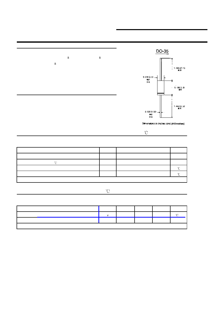
Case: DO-35 glass case
.
Polarity: Color band denotes cathode end
.
Weight: Approx. 0.13gram
ABSOLUTE MAXIMUM RATINGS(LIMITING VALUES)(T
A
=25 )
Symbols
Units
Zener current see table "Characteristics"
Power dissipation at T
A
=75
P
tot
mW
Junction temperature
T
J
Storage temperature range
T
STG
1)Valid provided that at a distance of 8mm from case are kept at ambient temperature(DO-35)
ELECTRICAL CHARACTERISTICS(TA=25 )
Symbols
Min.
Typ.
Max.
Units
Thermal resistance junction to ambient
R
JA
300
1)
/W
Forward voltage at I
F
=200mA
V
F
1.5
1)Valid provided that leads at a distance of 8mm from case are kept at ambient temperature
Value
500
1)
175
-65 to + 175
Copyright @ 2000 SHANGHAI CHENYI ELECTRONICS CO.,LTD
Page 1 of 2
CE
1N957 THRU 1N978
CHENYI ELECTRONICS
0.5W SILICON PLANAR ZENER DIODES
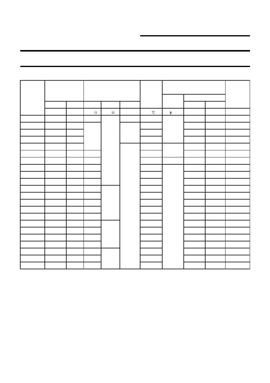
1N957...1N978 SILICON PLANAR ZENER DIODES
Maximum
Typical
Maximum
zener
Tempetature
Regulator
impedence
1)
coefficient
Current
V
ZNOM
I
ZT
Z
ZT
Z
ZK
I
ZK
suffix A suffix B I
ZM 2)
V mA mA %/
A
V
V
mA
1N957
6.8
18.5
4.5
1
0.050
150
4.9
5.2
47
1N958
7.5
16.5
0.058
75
5.4
5.7
42
1N959 8.2 15 0.062 50 5.9 6.2 38
1N960
9.1
14
0.068
10
6.6
6.9
35
1N961
10
12.5
0.075
7.2
7.6
32
1N962
11
11.5
5
0.076
8
8.4
28
1N963
12
10.5
11.5
0.077
8.6
9.1
26
1N964
13
9.5
13
0.079
9.4
9.9
24
1N965
15
8.5
16
0.082
10.8
11.4
21
1N966
16
7.8
17
0.083
11.5
12.2
19
1N967
18
7
21
0.085
13
13.7
17
1N968
20
6.2
25
0.086
14.4
15.2
15
1N969
22
5.6
29
0.087
15.8
16.7
14
1N970
24
5.2
33
0.088
17.3
18.2
14
1N971
27
4.6
41
0.090
19.4
20.6
11
1N972
30
4.2
49
0.091
21.6
22.8
10
1N973
33
3.8
58
0.092
23.8
25.1
9.0
1N974
36
3.4
70
0.093
25.9
27.4
8.5
1N975
39
3.2
80
0.094
28.1
29.7
7.8
1N976
43
3
93
0.095
31
32.7
7.0
1N977
47
2.7
105
0.095
33.8
35.8
6.4
1N978
51
2.5
125
0.096
36.7
38.8
5.9
Notes:
(1)The Zener impedance is derived from the 1kHz Ac voltage which results when an AC current having an RMS value equal to 10%
of the Zener current (I
ZT
)
is suprimposed on I
ZT
Zener impedance is measured at two points to insure a sharp knee on the
breakdown curve and to eliminate unstable units.
(2)Valid provided that leads are kept at ambient temperature at a distance of 8mm from case
(3) Measured with device junction in thermal equilibrium.
5.5
700
750
5
5
1000
1500
0.5
0.25
Type
Zener Voltage Range
3)
I
R 2)
Maximum Reverse
Leakage Current
Test-Voltage
Copyright @ 2000 SHANGHAI CHENYI ELECTRONICS CO.,LTD
Page 2 of 2