 | –≠–ª–µ–∫—Ç—Ä–æ–Ω–Ω—ã–π –∫–æ–º–ø–æ–Ω–µ–Ω—Ç: GL8E03M | –°–∫–∞—á–∞—Ç—å:  PDF PDF  ZIP ZIP |

169
Notice
In the absence of confirmation by device specification sheets,SHARP takes no responsibility for any defects that may occur in equipment using any SHARP devices shown in
catalogs,data books,etc.Contact SHARP in order to obtain the latest device specification sheets before using any SHARP device.
Internet
Internet address for Electronic Components Group http://www.sharp.co.jp/ecg/
Numeric
L
ED
Numeric LED
s
General Description
Sharp can supply wide color line-up for numeric LEDs-GaAlAs on GaAlAs
(double hetero) super-luminosity U series (red), S series (sunset orange), K
series (green). In addition to them, dichromatic type has realized an expressive
display, changing the emission color according to display contents.
Sharp can also supply various character height (7.62mm to 38.1mm), and
various digits type (1digit to 5digits) for your applications.
s
Structure
Numeric LEDs are classified into 2 types ; substrate type and mold type as shown below.
Substrate type employs thin package and can save the mount space. Mold type has realized
high reliability because it is molded by resin.
,,
,,,
,
,,
,,,
,
,,
,,,
,,
,,
,,,
,,
Reflective case
Scattering sheet
Reflective case
Substrate
Lead pin
Epoxy resin
Lead frame
Mold Type
Substrate Type
GL
q
Type: internal connection
e
Character size
w
Radiation color
1-digit
GL
e
Serial No.
r
No. of digits
w
Radiation color
q
Type: internal connection
Multi-digits
Numbering system
3
6
7
8
9
Multi-digits Dynamic drive circuit
Multi-digits Cathode common
Multi-digits Anode common
1-digit Cathode common
1-digit Anode common
Radiation color
Red
Red(Super-luminosity)
Red(High-luminosity)
Red
Sunset orange
Yellow
Yellow-green
Green
Yellow-green+Red
Yellow-green+Red(High-luminosity)
Series
P
U
T
D
S
H
E
K
ED
ET
03,030
04,040
156
56
08
100
15
8.0mm
10.16mm
14.12mm
14.22mm
20.32mm
25.4mm
38.1mm
2
3
4
5
2-digits
3-digits
4-digits
5-digits
q
Type: internal connection
w
Radiation color
e
Character size
r
No. of digits
GL3E305
GL6S220
GL9D030
GL9H040
GL8T156
GL3H412
GL3T508D

170
Notice
In the absence of confirmation by device specification sheets,SHARP takes no responsibility for any defects that may occur in equipment using any SHARP devices shown in
catalogs,data books,etc.Contact SHARP in order to obtain the latest device specification sheets before using any SHARP device.
Internet
Internet address for Electronic Components Group http://www.sharp.co.jp/ecg/
Surface Mount Type Numeric LED
s
General Description
Sharp's GL8D03M series, GL8D04M series, GL8D56M series are 1-digit, thin
package surface mount type numeric LEDs. (character height: 8.0/10.16/14.22
mm). It is unnecessary to adjust the mounting height because the thickness of
each series is the same. They are suited for measuring equipment and various
thin type display systems.
s
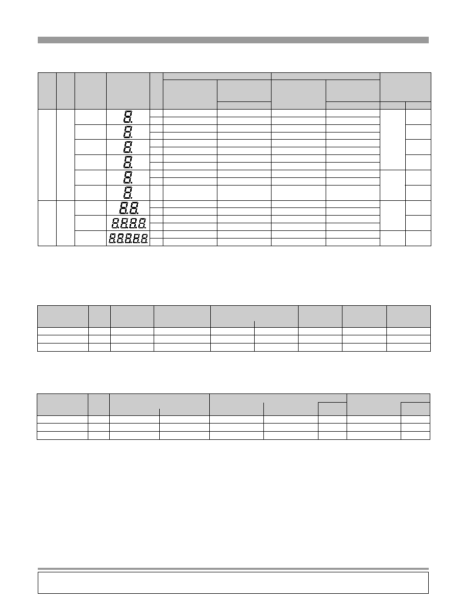
Model Line-up
Type
Character
height
(mm)
Radiation
color
Common
D
Red
E
Yellow-green
Outline Dimensions
Page
Figure
Mold
type
8.0
Anode
GL9D03M
GL9E03M
180
1
Cathode
GL8D03M
GL8E03M
10.16
Anode
GL9D04M
GL9E04M
180
2
Cathode
GL8D04M
GL8E04M
14.22
Anode
GL9D56M
GL9E56M
180
3
Cathode
GL8D56M
GL8E56M
Model No.
Forward current
I
F
(mA)
Peak forward current
*1
I
FM
(mA)
Derating factor
Reverse voltage
V
R
(V)
Operating temperature
T
opr
(∞C)
Storage temperature
T
stg
(∞C)
DC
(mA/∞C)
Pulse
(mA/∞C)
GL9E03M/GL8E03M
Yellow-green
15
50
1.91
6.36
5
-30 to +70
-40 to +80
GL9D03M/GL8D03M
Red
20
50
2.54
6.36
5
GL9E04M/GL8E04M
Yellow-green
15
50
1.91
6.36
5
-30 to +70
-40 to +80
GL9D04M/GL8D04M
Red
20
50
2.54
6.36
5
GL9E56M/GL8E56M
Yellow-green
15
50
1.91
6.36
5
-30 to +70
-40 to +80
GL9D56M/GL8D56M
Red
20
50
2.54
6.36
5
Model No.
Forward current
V
F
(V)
Luminous intensity
Peak emission wavelength
Spectrum radiation bandwidth
Reverse current
I
V
(mcd)
TYP.
p (nm)
TYP.
(nm)
TYP.
I
F
(mA)
I
R
(µA)
MAX.
V
R
(V)
TYP.
MAX.
GL9E03M/GL8E03M
Yellow-green
2.0
2.5
2.5
565
30
10
10
4
GL9D03M/GL8D03M
Red
1.85
2.3
2.3
635
35
10
10
4
GL9E04M/GL8E04M
Yellow-green
2.0
2.5
3.0
565
30
10
10
4
GL9D04M/GL8D04M
Red
1.85
2.3
3.0
635
35
10
10
4
GL9E56M/GL8E56M
Yellow-green
2.0
2.5
4.0
565
30
10
10
4
GL9D56M/GL8D56M
Red
1.85
2.3
4.0
635
35
10
10
4
s
Absolute Maximum Ratings
(Figures shown below are values per segment.)
s
Electro-optical Characteristics (Figures shown below are values per segment.)
(Ta=25∞C)
*1 Duty ratio=1/10, pulse width=0.1ms
(Ta=25∞C)
GL9D04M

171
Notice
In the absence of confirmation by device specification sheets,SHARP takes no responsibility for any defects that may occur in equipment using any SHARP devices shown in
catalogs,data books,etc.Contact SHARP in order to obtain the latest device specification sheets before using any SHARP device.
Internet
Internet address for Electronic Components Group http://www.sharp.co.jp/ecg/
Numeric
L
ED
Dichromatic Numeric LED
s
General Description
Sharp's dichromatic numeric LEDs GL9ED08 series, GL8ED100 series are 1-digit
large size numeric LEDs(character height: 20.32/25.4mm). They have realized
expressive display, changing the radiation color according to display type.
They are suited for measuring equipment, amusement equipment, and various
displays.
Type
Mold
type
20.32
25.40
181
180
8
6
Anode
Anode
Cathode
GL9ED08
GL9ED100
GL8ED100
GL9ET100
GL8ET100
Character height
(mm)
Radiation color
common
E D
Yellow-green+Red
E T
Yellow-green+Red(High-luminosity)
Outline dimensions
Page
Figure
s
Model Line-up
Model No.
Forward current
I
F
(mA)
Peak forward current
*1
I
FM
(mA)
Derating factor
DC
(mA/∞C)
Pulse
(mA/∞C)
Reverse voltage
V
R
(V)
Operating temperature
T
opr.
(∞C)
Storage temperature
T
stg.
(∞C)
GL9ED08
GL8ED100
GL9ED100
GL8ET100
GL9ET100
20
20
20
20
20
50
50
50
50
100
0.36
0.36
0.36
0.36
0.36
0.91
0.91
0.91
0.91
1.82
5
6
6
6
6
-30 to +70
-30 to +70
-30 to +70
-40 to +80
-40 to +80
-40 to +80
Yellow-green
Yellow-green
Red
Yellow-green
Red(High-luminosity)
*1 Duty ratio=1/10, Pulse width=0.1ms
(Ta=25∞C)
s
Absolute Maximum Ratings (Figures shown below are values per segment.)
Model No.
Forward current
V
F
(V)
TYP. MAX.
Luminous intensity
I
V
(mcd)
TYP.
Peak emission wavelength
p(nm)
TYP.
Spectrum radiation bandwidth
(
nm)
TYP.
I
F
(mA)
V
R
(V)
Reverse current
I
R
(
µ
A)
MAX.
GL9ED08
GL8ED100
GL9ED100
GL8ET100
GL9ET100
2.0
4.0
3.7
4.0
3.4
2.5
5.0
5.0
5.0
4.4
3.0
3.5
3.5
3.5
4.8
565
565
635
565
660
30
30
35
30
20
10
10
10
10
10
10
10
10
10
10
4
5
5
5
5
Yellow-green
Yellow-green
Red
Yellow-green
Red(High-luminosity)
(Ta=25∞C)
s
Electro-optical Characteristics (Figures shown below are values per segment.)
GL8ED100
172
Notice
In the absence of confirmation by device specification sheets,SHARP takes no responsibility for any defects that may occur in equipment using any SHARP devices shown in
catalogs,data books,etc.Contact SHARP in order to obtain the latest device specification sheets before using any SHARP device.
Internet
Internet address for Electronic Components Group http://www.sharp.co.jp/ecg/
Super-luminosity/High-luminosity Numeric LED
181
180
182
183
Digit
1-digit
Mold Type
Multi-digits
Mold Type
Type
Type of display
Outline dimensions
Model No.
Luminous intensity
(mcd)
TYP.
Model No.
Luminous intensity
(mcd)
TYP.
Page
Figure
*1
Common pins
Character
height
(mm)
U (Red)
T (Red)
8.0
10.16
14.12
20.32
25.4
38.1
10.16
8.0
7.6
11
10
9
7
5
4
13
18
20
A
K
A
K
A
K
A
K
A
K
A
A
K
A
K
A
K
GL9U100
GL9U15
35.0
27.0
GL9T030
GL8T030
GL9T040
GL8T040
GL9T156
GL8T156
GL9T08
GL8T08
GL9T100
GL8T100
GL7T201
GL6T201
GL3T422
GL3T421
GL3T508D
GL3T507D
4.0
4.0
4.25
4.25
5.25
5.25
2.2
2.2
9.5
9.5
4.25
4.25
1.5
1.5
1.5
1.5
*1 A: Anode common K: Cathode common * Production after order confirmation
* As for current conditions, refer to I
F
in electro-optical characteristics.
(Ta=25∞C)
s
Super-luminosity/High-luminosity Numeric LED
Figures shown below are values per segment.
Character height
(mm)
Forward current
I
F
(mA)
Peak forward current
I
FM
*1
(mA)
Derating factor
(mA/ ∞C)
Reverse voltage
V
R
(V)
Operating temperature
T
opr.
(∞C)
Storage temperature
T
stg.
(∞C)
Radiation
color
*1 Duty ratio=1/10, Pulse width=0.1ms
*2 U type duty ratio=1/16, pulse width=0.1ms
8.0/10.16/14.12/20.32
25.4, 38.1
25.4, 38.1
T
U
T
20
20
20
100
150
*2
100
0.36
0.36
0.36
5
6
5
-30 to +70
-30 to +70
-30 to +70
-40 to +80
-40 to +80
-40 to +80
1.82
2.73
1.82
DC
Pulse
(Ta=25∞C)
s
Absolute Maximum Ratings
Figures shown below are values per segment.
Character height
(mm)
Forward current
V
F
Peak emission wavelength
p(nm)
TYP.
Radiation
color
8.0/10.16/14.12/20.32
25.4, 38.1
25.4, 38.1
T
U
T
1.7
3.5
3.4
2.2
4.8
4.4
660
660
660
Spectrum radiation bandwidth
(
nm)
TYP.
I
F
(mA)
20
20
20
10
10
10
Reverse current
I
R(
µ
A)
MAX.
V
R
(V)
10
100
10
4
5
4
TYP.
MAX
(Ta=25∞C)
s
Electro-optical Characteristics
Figures shown below are values per segment.

173
Notice
In the absence of confirmation by device specification sheets,SHARP takes no responsibility for any defects that may occur in equipment using any SHARP devices shown in
catalogs,data books,etc.Contact SHARP in order to obtain the latest device specification sheets before using any SHARP device.
Internet
Internet address for Electronic Components Group http://www.sharp.co.jp/ecg/
Numeric
L
ED
Numeric LED
Mold Type
Page for ratings/characteristics diagrams
Type
Type of display
Outline dimensions
P
Red
176
Page
Figure
*1
Common pins
Radiation color
Character
height
(mm)
8.0
10.16
14.12
25.4
11
10
9
5
A
K
A
K
A
K
A
K
GL9P030
GL8P030
GL9P040
GL8P040
GL9P156
GL8P156
181
180
D
Red
177
GL9D030
GL8D030
GL9D040
GL8D040
GL9D156
GL8D156
GL9D100
GL8D100
S
Sunset orange
178
GL9S030
GL8S030
GL9S040
GL8S040
GL9S156
GL8S156
GL9S100
GL8S100
H
Yellow
178
GL9H030
GL8H030
GL9H040
GL8H040
GL9H156
GL8H156
GL9H100
GL8H100
E
Yellow-green
179
GL9E030
GL8E030
GL9E040
GL8E040
GL9E156
GL8E156
GL9E100
GL8E100
K
Green
179
GL9K030
GL8K030
GL9K040
GL8K040
GL9K156
GL8K156
*1 A: Anode common K: Cathode common
s
1-digit
Character
height
(mm)
Forward current
I
F
(mA)
Peak forward current
I
FM
(mA)
Derating factor
(mA/∞C)
Reverse voltage
V
R
(V)
Operating temperature
T
opr.
(∞C)
Storage temperature
T
stg.
(∞C)
Radiation color
6.0
6.2
7.6
8.0
8.4
10.16
14.12
20.32
(common)
25.4
P
D
S
H
E
K
D
S
H
E
50
50
50
50
50
50
50
50
50
50
0.91
0.91
0.91
0.91
0.91
0.91
0.91
0.91
0.91
0.91
5
5
5
5
5
5
6
6
6
6
10
(15)
*2
20
20
20
15
15
20
20
20
20
0.18
(0.27)
0.36
0.36
0.36
0.27
0.27
0.36
0.36
0.36
0.36
-30 to +70
-30 to +70
-30 to +70
-30 to +70
-30 to +70
-30 to +70
-30 to +70
-30 to +70
-30 to +70
-30 to +70
-40 to +80
-40 to +80
-40 to +80
-40 to +80
-40 to +80
-40 to +80
-40 to +80
-40 to +80
-40 to +80
-40 to +80
DC
Pulse
(Ta=25∞C)
*1 Duty ratio=1/10, Pulse width=0.1ms
*2 ( ): figures for GL8/9P040, GL8/9P056, GL8/9P156, GL6/7P220
*1
s
Absolute Maximum Ratings(Mold Type)
Figures shown below are values per segment.
Character
height
(mm)
Forward current
I
F
(mA)
Peak forward current
I
FM
(mA)
Derating factor
(mA/∞C)
Reverse voltage
V
R
(V)
Operating temperature
T
opr.
(∞C)
Storage temperature
T
stg.
(∞C)
Radiation color
7.6
P
50
1.11
5
15
0.15
-10 to +60
-20 to +70
DC
Pulse
(Ta=25∞C)
*1 Duty ratio=1/10, Pulse width=0.1ms
*1
s
Absolute Maximum Ratings(Substrate Type)
Figures shown below are values per segment.