 | –≠–ª–µ–∫—Ç—Ä–æ–Ω–Ω—ã–π –∫–æ–º–ø–æ–Ω–µ–Ω—Ç: GP2A22 | –°–∫–∞—á–∞—Ç—å:  PDF PDF  ZIP ZIP |
GP2A20/GP2A22
GP2A20/GP2A22
1 Collector-emitter voltage of output transistor
2 Collector current of output transistor
3 The connector should be plugged in/out at normal temperature.
s
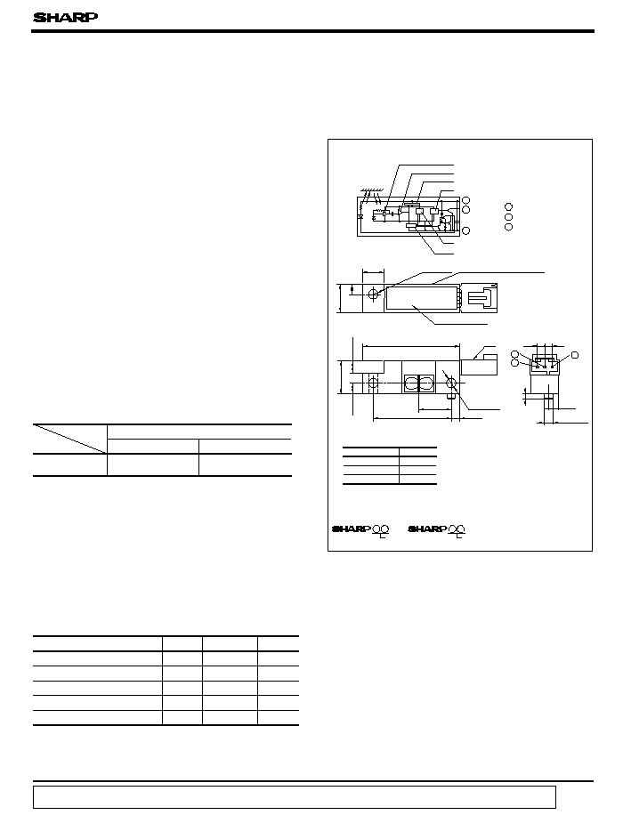
Outline Dimensions
(Unit : mm )
s
Features
s
Absolute Maximum Ratings
s
Applications
(Ta= 25∞C)
Parameter
Symbol
Rating
Unit
Supply voltage
V
CC
- 0.5 to 7
V
1
Output voltage
V
O
30
V
2
Low level output current
I
OL
50
mA
3
Operating temperature
T
opr
- 10 to + 60
∞C
3
T
stg
- 20 to + 80
∞C
1. Light modulation type, free from external
disturbing light
2. Long focal distance type
(
GP2A20
: 3 to 7mm )
(
GP2A22
: 9 to 15mm )
3. Capable of TTL direct connection
1. Copiers
2. Laser beam printers
3. Facsimiles
Oscillator
Synchronous detection
Demodulator circuit
Voltage regulator
Comparator
Amp.
Internal connection diagram
7.0
3.5
9.6
R4.0
33.0
26.5
11.0
11.0
4.0
3.5
3.0
g
Resin sealed
3.5
2.0
1
2
3
Lot No.
3 GND
Dimensions(d) Tolerance
d
<
6.0
±
0.2
6.0
<=
d
<
14.0
±
0.3
14
<=
d
±
0.4
( )
:
Reference dimensions
Marking
:
GP2A20
(2.5)
(2.5)
Unspecified tolerances shall be as follows
;
g
MOLEX JAPAN CO.,
LTD made
3
-
pin connector
52135
-
0350
Housing SD-51030-0310
Terminal SD-50084-8100
Lot No.
Detecting range
3 to 7mm
Model No.
GP2A20
GP2A22
GP2A22
9 to 15mm
1
2
3
Light Modulation, Long Focal
Distance Type OPIC
Photointerrupter
4. With 3-pin connector provided for easier
interface with peripheral control circuit
s
Line-ups
Detecting range
Storage temperature
Marking on the side
An OPIC consists of a light-detecting element and signal-
processing circuit integrated onto a single chip.
*" OPIC " ( Optical IC ) is a trademark of the SHARP Corporation.
data books, etc. Contact SHARP in order to obtain the latest version of the device specification sheets before using any SHARP's device.
"
"
In the absence of confirmation by device specification sheets, SHARP takes no responsibility for any defects that occur in equipment using any of SHARP's devices, shown in catalogs,
1 V
CC
2 V
O
3
-
3.2
3.0
+
0
-
0.2
( V
CC
= 5V, Ta= 25∞C)
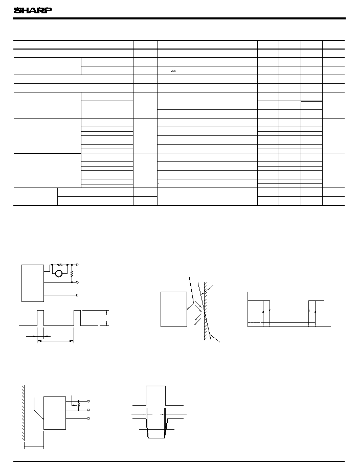
Pulse Value )
6 Test Condition for Response Time
4 Test Condition for Dissipation Current ( Peak
GP2A20/GP2A22
GP2A22
r
=
1
V
O
GND
V
r
OHP paper
V
OH
V
OL
L
LHS
L
HLS
L
HLL
L
LHL
t
W
t
P
V
Detection
surface
=±
5deg.
(GP2A20)
(GP2A22)
Output signal ( with pull-up resistor )
Reflective
object
I
CCP
=
V
r
/1
t
P
(TYP.)
=
130
µ
s
t
W
(TYP.)
=
8
µ
s
GP2A20/
V
CC
=
5V
R
L
=
1k
V
OUT
GND
GP2A20/
GP2A22
V
OH
1.5V
V
OL
t
PHL
t
PLH
L
Detection
surface
R
L
=
1k
V
out
Waveform
V
CC
=
5V
Reflective
object
:
Kodak 90
%
reflective paper
Parameter
Symbol
Operating supply voltage
V
CC
Dissipation current
Peak pulse value
I
ccp
Smoothing value
I
CC
Low level output voltage
V
OL
High level output voltage
V
OH
time
Response
" High
Low"
propagation delay time
" Low
High"
propagation delay time
Non-detecting
distance
Minimum detecting
distance
Maximum detecting
distance
L
LHL
L
HLS
L
HLL
MIN.
TYP.
MAX.
Unit
4.75
-
5.25
V
-
-
mA
-
-
mA
-
-
0.4
V
4.5
-
-
V
-
-
20
-
-
mm
50
-
-
25
-
-
3.0
-
-
1.0
mm
-
-
7.0
-
-
9.0
-
-
3.0
-
-
9.0
7.0
-
-
9.0
-
-
mm
17.0
-
-
15.0
-
-
7.0
-
-
15.0
-
-
-
-
1
ms
-
-
1
ms
Conditions
R
L
=
I
OL
= 16mA at detecting time
R
L
= 1k
at non-detecting time
Reflective object:
5
Kodak 90% reflective paper
Reflective object:
5
Chloroprene rubber
Reflective object:
5
Artwork tape
Reflective object:
5
Kodak 90% reflective paper
Reflective object:
5
Black paper
Reflective object:
5
OHP paper,
Reflective object:
5
Artwork tape
Reflective object:
5
Kodak 90% reflective paper
Reflective object:
5
Black paper
6
GP2A20
GP2A22
GP2A20
GP2A20
GP2A22
GP2A22
GP2A20
GP2A22
GP2A20
GP2A20
GP2A22
GP2A22
GP2A20
GP2A22
4
r= 1
t
PHL
t
PLH
= 5deg. ( X,Y direction )
= 5deg. (X,Y direction )
5
Reflective object: OHP paper,
150
30
GP2A22
GP2A20/
s
Electro
-
optical Characteristics
With reflective object
Without reflective object
5 Test Condition for Detecting Distance
Characteristics
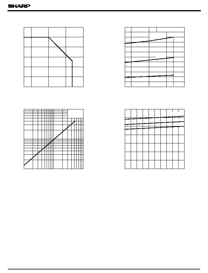
60
50
40
30
20
10
0
60
75
50
25
0
- 10
- 10
0
25
50
75
60
0.3
0.2
0.1
0
16mA
5mA
1
0.01
2
5
10
20
50
100
0.02
0.05
0.1
0.2
0.5
1
4.75
5.0
5.25
5
7
2
3
1
0
4
6
25∞C
60∞C
Fig. 1 Low Level Output Current vs.
Ambient Temperature
Fig. 2 Low Level Output Voltage vs.
Ambient Temperature
Low level output current I
OL
(
mA
)
Ambient temperature T
a
(∞C)
Low level output voltage V
OL
(
V
)
Ambient temperature T
a
( ∞C)
Fig. 3 Low Level Output Voltage vs.
Low Level Output Current
Low level output voltage V
OL
(
V
)
Low level output current I
OL
( mA )
Dissipation current I
CC
(
mA
)
GP2A20/GP2A22
s
Precautions for Use
Fig. 4 Dissipation Current (Smoothing Value )
vs. Supply Voltage
( 3) Remove dust or stains, using an air blower or a soft cloth moistened in cleaning solvent.
( 1) In order to stabilize power supply line, connect a by-pass capacitor of more than 0.33
µ
F
Supply voltage V
CC
(V)
T
a
= 25∞C
V
CC
= 5V
T
a
=- 10∞C
V
CC
= 5V, at detecting time
I
OL
= 30mA
( 4) As for other general cautions, refer to the chapter "Precautions for Use .
"
( 2) Please do not perform dip cleaning or ultrasonic cleaning because lens part of this
When the cleaning solvents except for specified materials are used, please consult us.
between Vcc and GND nea
product is an optical device of acrylic resin.
However, do not perform the above cleaning using a soft cloth with cleaning solvent in the
marking portion.
In this case, use only the following type of cleaning solvent used for wiping off :
Ethyl alcohol, Methyl alcohol, Isopropyl alcohol