1
D
a
te of Is
sue
16.
08.20
00
Subject to reasonable modifications due to technical advances.
Copyright Pepperl+Fuchs, Printed in Germany
Pepperl+Fuchs Group ∑ Tel.: Germany (06 21) 7 76-0 ∑ USA (330) 4 25 35 55 ∑ Singapore 7 79 90 91 ∑ Internet http://www.pepperl-fuchs.com
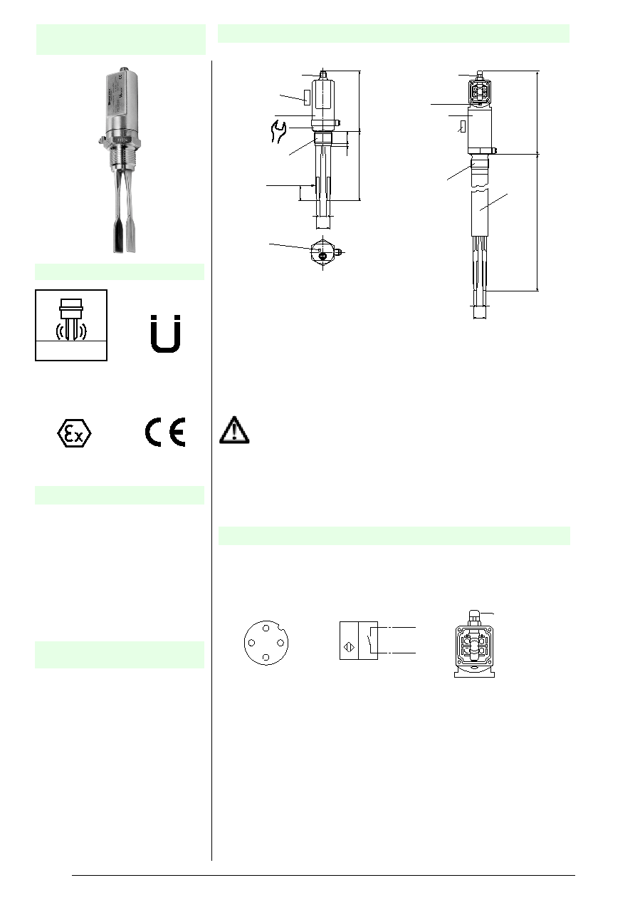
Vibrating
Limit Switch LVL
∑ Vibration limit switch for liquids
∑ Ex-version with intrinsically safe
NAMUR-switching signal, applicable
in Ex-Zone 0
∑ Lead short circuit and lead breakage
control
∑ Stainless steel housing for rough
environmental conditions
∑ Function test with testing magnet in
mounted position.
∑ Put the testing magnet to the shown
location. The state of the output will
be the same as with a covered
vibration fork.
LVL-N
Features
Function test with the testing
magnet
Dimensions
Function principle
The vibration fork is actuated piezoelectrically. It is vibrating with its resonance
frequency in air. Liquids getting into contact with the fork are changing this
frequency. This change is evaluated electronically and produces the switching
signal.
Electrical connection
V1 connector
PG9
Testing magnet
Testing magnet
Housing
Housing
LED
Switching point
LED
Switching state (yellow)
41
G1A
G1A
Compact version
LVL1
ooo
-V1
Extended version
LVL2
ooo
-PG
¯29
10
22
25
127
5.5
19
110
22
10
120
L
Please specify the length (L) if you order an extended version.
The testing magnet has to be ordered separately (accessory).
For a V1-connection - the necessary accessory is a V1 cable connection
box (see accessories).
1 / BN
2 / BU
+
-
1 = +
2 = -
Plug connector V1
Electrical connection
1
2
4
3
PG9
3 = +
4 = -
N
V
Terminal compartment
connection
3
4
2
D
a
te of Is
sue
16.
08.20
00
Subject to reasonable modifications due to technical advances.
Copyright Pepperl+Fuchs, Printed in Germany
Pepperl+Fuchs Group ∑ Tel.: Germany (06 21) 7 76-0 ∑ USA (330) 4 25 35 55 ∑ Singapore 7 79 90 91 ∑ Internet http://www.pepperl-fuchs.com
Vibrating Limit Switch
LVL-N
Technical data
Approvals/Certifications
Information about approvals and
certifications can be found at
www.pepperl-fuchs.com.
Z.65-11.172 (Wasserhaushaltsgesetz WHG ß 19)
DMT 98 ATEX E 004 (acc. to directive 94/9/EG
(ATEX): II 1G, II ΩD, II
1
/
3
D) (Explosion Protection)
13376-98HH (Germanischer Lloyd)
Ignition protection class
Gas-Ex:
EEx ia IIC
EEx ia IIB
LVL
oo
-
ooo
-N-PG
Dust Ex:
IP65 T 160 ∞C
Device groups
Gas-Ex-zone 0:
all variants
Dust-Ex-zone 20/21:
LVL
oo
-
ooo
S-N-CSM
Dust-Ex-zone 20/22:
LVL
oo
-
ooo
-N-PG
Data according to the
design test certificate
U
i
I
i
P
i
£
16 V
£
88 mA
£
198 mW
Supply
Nominal voltage
Nominal current
max. self capacitance
max. self inductance
Protection class
according to EN 60947-5-6 (NAMUR)
DC 8.2 V ± 2 % from the isolation amplifier
unswitched <1.2 mA/switched >2.1 mA
negligible
<
60
m
H
lll
Function test
Performed with test magnet (accessories) on
mounted device. Sequential circuits can be proved
(like PLCs or control systems) without demounting
the device and without media contact.
Switching delay
when covering
when uncovering
approx. 0.5 s
approx. 0.5 s
Indicators
Switching state
LED, yellow
Temperature conditions
Ambient temperature
-25 ∞C ... +70 ∞C
Limitation in dust-Ex-zone 21 and 22:
Media temperature
-25 ∞C ... +120 ∞C
Limitation in gas-Ex:
Limitation in dust Ex-zone 20:
Process conditions
Pressure
Density
r
Viscosity
£
40 bar
≥
0.6 g/cm
3
max. 10 000 mPa s
Protection class acc. to IEC 60529
IP67
max. surface temperature
sensor housing ∞C
50
80
Ambient temperature ∞C
40
70
Temperature class
T6
T5
T4
T3
Media temperature
∞C
<80
<95
<120 <120
max. surface temp. of
the fork ∞C
50
80
120
120
Media temperature ∞C
40
70
120
120
Compact version LVL1
∑ LVL1S-G3S-N-V1
fork: stainless
steel housing: plastic
∑ LVL1O-G3OS-N-V1
fork: polished stainless steel
housing: stainless steel
Extended version LVL2
∑ LVL2S-G3S-N-V1
fork: stainless steel
housing: plastic
∑ LVL2O-G3OS-N-V1
fork: polished stainless steel
housing: stainless steel
1" NPT-version
∑ all types are available with 1" NPT
threadtype LVL
oo
-N3
o
-N-V1
∑ V1-G-N-5M-PUR, cable connection
box, straight
∑ V1-G-N-5M-PUR, cable connection
box, straight, with 5 m cable
∑ V1-W-N-5M-PUR, cable connection
box, 90∞ angled
∑ V1-W-N-5M-PUR, cable connection
box, 90∞ angled, with 5 m cable
∑ LVL-Z15, test magnet
∑ LVL2-Z41, sliding bushing G1ΩA,
stainless steel 1.4571 (for
unpressurised operation)
∑ LVL2-Z49, sliding bushing G1ΩA,
PVC (for unpressurised operation)
∑ LVL-Z61, welding bushing for vessels
G1, Viton sealing
∑ a vibration limit switch LVL-N, a cable
connection box and a transformer
isolated barrier
e. g. KFD2-SR2-Ex1.W
Conventional versions
Accessories
A measuring system consists
of:
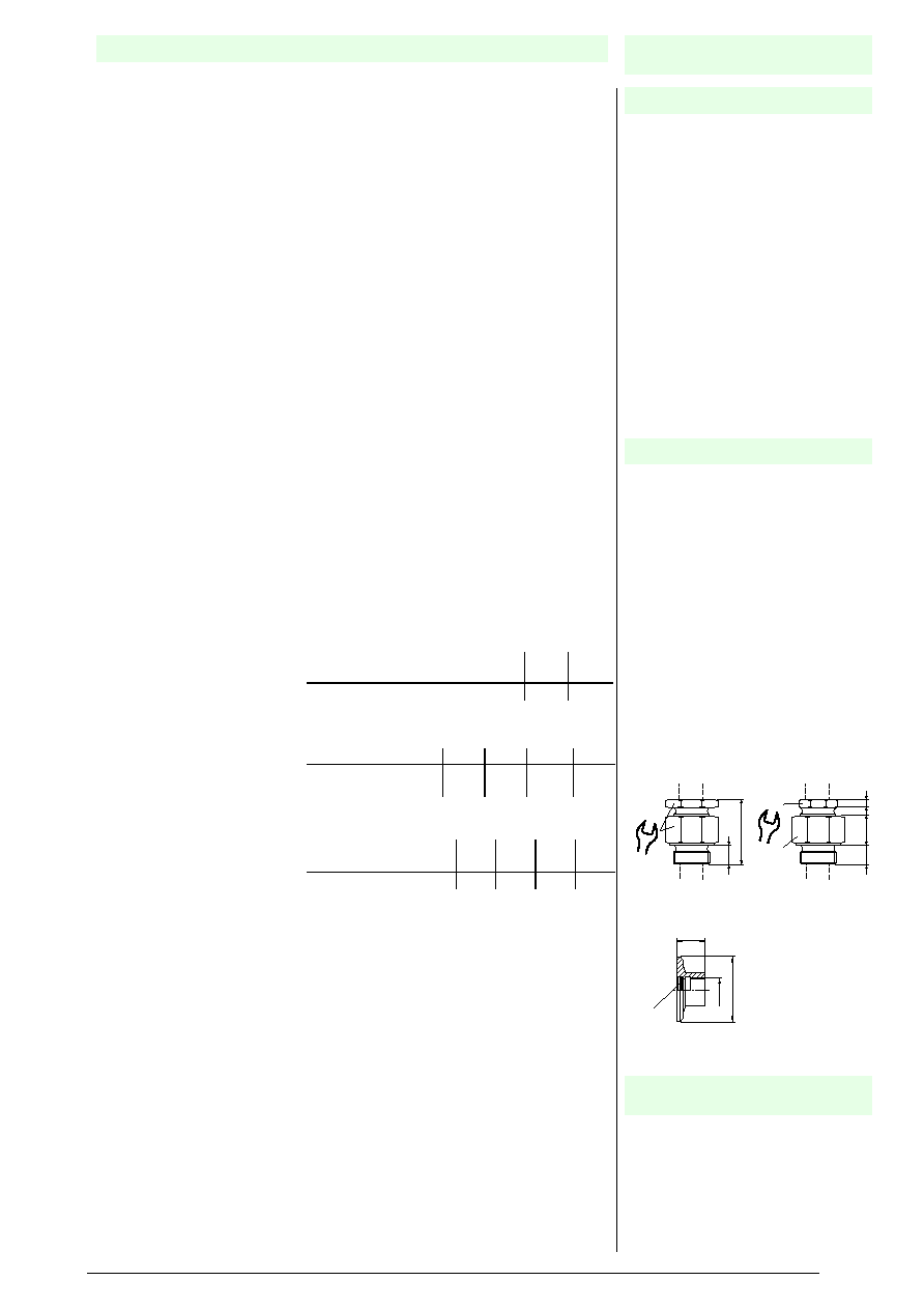
Viton sealing
¯
60
27
G1
Welding bushing
LVL-Z61
Sliding bushing G1ΩA
LVL2-Z41, stainless steel
SW 60
22
78
Sliding bushing G1ΩA
LVL2-Z49, PVC
SW 60
SW 41
30
20
10
3
D
a
te of Is
sue
16.
08.20
00
Subject to reasonable modifications due to technical advances.
Copyright Pepperl+Fuchs, Printed in Germany
Pepperl+Fuchs Group ∑ Tel.: Germany (06 21) 7 76-0 ∑ USA (330) 4 25 35 55 ∑ Singapore 7 79 90 91 ∑ Internet http://www.pepperl-fuchs.com
Vibrating Limit Switch
LVL-N
∑ When using a sliding bushing, special
attention must be paid to the
resistance of the sealing
rings and plastic material to the
medium that is involved. Faults lead
to a down grading in zone
classification.
∑ On versions with Varivent, milk tube
or Triclamp connection, it must be
ensured that they are safely isolated
in zone 0.
∑ On flanged versions, the flange rated
pressure must not be exceeded.
∑ When using the external connections
for the equipotential bonding
conductor, these should be smeared
with terminal grease.
Notes
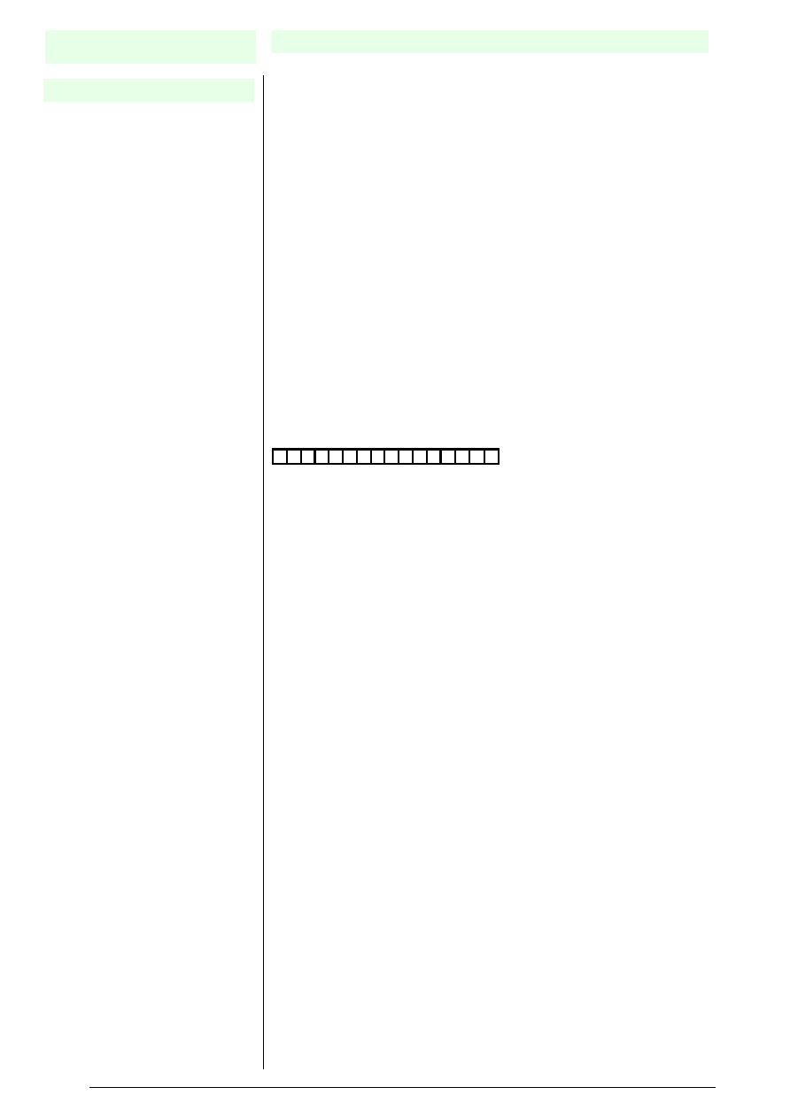
Key to model numbers/ordering code
Vibracon LVL-Namur
Measuring range
1 Compact version
2 Extended version, rod length 170 mm ... 3000 mm
| Surface of fork
|
S Stainless steel (1.4581)
|
O Polished stainless steel (1.4581)
|
H ECTFE (Halar coated)(in combination with process connection F*and A*)
|
C Hasteloy C (2.4610)(in combination with process connection G3, N3, FC, AC)
|
|
Process connection
|
|
G
3 G1A thread
|
|
N
3 1" NPT thread
|
|
M
4 Milk pipe DN40, DIN11851
|
|
T
2 Triclamp 2"
|
|
F
1 Flange DN50 PN40
|
|
F
C Flange DN50 PN40 (Hastelloy C plated)
|
|
A
2 Flange ANSI 2", 150 lbs
|
|
A
C Flange ANSI 2", 150 lbs (Hastelloy C plated)
|
|
-
-
other process connections
|
|
|
| Material/surface process connection
|
|
|
|
S Stainless steel (1.4571)
|
|
|
|
O Polished stainless steel (1.4571)
|
|
|
|
H ECTFE (Halar coated)(in combination with process connection F*and A*)
|
|
|
|
C Hasteloy C (2.4610)(in combination with process connection G3, N3, FC, AC)
|
|
|
|
| Material housing
|
|
|
|
|
/ Plastic (PBT), with V1 connection
|
|
|
|
|
S Stainless steel, with V1 connection or terminal compartment connection PG9
|
|
|
|
|
|
Electrical output
|
|
|
|
|
|
N According to EN 60947-5-6 (Namur)
|
|
|
|
|
|
|
Specialities
|
|
|
|
|
|
|
V
1
Plug connection
|
|
|
|
|
|
|
P
G Terminal compartment connection PG9
|
|
|
|
|
|
|
|
|
Approvals
|
|
|
|
|
|
|
|
|
G Approval GL (only for stainless steel housing
and plug connector V1)
|
|
|
|
|
|
|
|
|
|
L V L
-
-
-