 | –≠–Ľ–Ķ–ļ—ā—Ä–ĺ–Ĺ–Ĺ—č–Ļ –ļ–ĺ–ľ–Ņ–ĺ–Ĺ–Ķ–Ĺ—ā: LGQ971-KO | –°–ļ–į—á–į—ā—Ć:  PDF PDF  ZIP ZIP |

Semiconductor Group
1
1998-08-28
VEO06989
Besondere Merkmale
q
Gehšusebauform: 0603
q
Industriestandard bzgl. LŲtpadraster
q
geringe BauteilhŲhe
q
fŁr IR-LŲtung geeignet
q
fŁr Hinterleuchtungen und als opt. Indikator einsetzbar
q
gegurtet (8-mm-Filmgurt)
Features
q
0603 package
q
Industry standard footprint
q
low profile
q
suitable for IR reflow soldering process
q
for use as optical indicator and backlighting
q
available taped on reel (8 mm tape)
Typ
Type
Emissions-
farbe
Color of
Emission
Farbe der
Lichtaustritts-
flšche
Color of the
Light Emitting
Area
Lichtstšrke
Luminous
Intensity
I
F
= 20 mA
I
V
(mcd)
Lichtstrom
Luminous
Flux
I
F
= 20 mA
V
(mlm)
Bestellnummer
Ordering Code
LG Q971-KO
green
colorless clear
6.30 (15 typ.)
120 (typ.)
Q62702-P5098
CHIPLED
LG Q971

Semiconductor Group
2
1998-08-28
LG Q971
Grenzwerte
Maximum Ratings
Bezeichnung
Parameter
Symbol
Symbol
Werte
Values
Einheit
Unit
Betriebstemperatur
Operating temperature range
T
op
≠ 30 ... + 85
įC
Lagertemperatur
Storage temperature range
T
stg
≠ 40 ... + 85
įC
Sperrschichttemperatur
Junction temperature
T
j
+ 95
įC
DurchlaŖstrom
Forward current
I
F
20
mA
StoŖstrom
Surge current
t
p
10
Ķ
s,
D
= 0.005
I
FM
0.1
A
Sperrspanung
Reverse voltage
V
R
5
V
Verlustleistung
Power dissipation
P
tot
55
mW
Wšrmewiderstand
Sperrschicht / Umgebung
Thermal resistance
Junction / air
R
th JA
800
K/W

Semiconductor Group
3
1998-08-28
LG Q971
Kennwerte (
T
A
= 25 įC)
Characteristics
Bezeichnung
Parameter
Symbol
Symbol
Werte
Values
Einheit
Unit
Wellenlšnge des emittierten Lichtes
(typ.)
Wavelength at peak emission
(typ.)
I
F
= 20 mA
peak
565
nm
Dominantwellenlšnge
(typ.)
Dominant wavelength
(typ.)
I
F
= 20 mA
dom
570
nm
Spektrale Bandbreite
(typ.)
Spectral bandwidth
(typ.)
I
F
= 20 mA
28
nm
Abstrahlwinkel bei 50 %
I
v
(Vollwinkel)
Viewing angle at 50 %
I
v
2
160
Grad
deg.
DurchlaŖspannung
(typ.)
Forward voltage
(max.)
I
F
= 20 mA
V
F
V
F
2.2
2.6
V
V
Sperrstrom
(typ.)
Reverse current
(max.)
V
R
= 5 V
I
R
I
R
0.01
10
Ķ
A
Ķ
A
Temperaturkoeffizient von
dom
(
I
F
= 20 mA)
Temperature coefficient of
dom
(
I
F
= 20 mA)
TC
0.06
nm/K
Temperaturkoeffizient von
peak
,
I
F
= 20 mA
(typ.)
Temperature coefficient of
peak
,
I
F
= 20 mA
(typ.)
TC
0.10
nm/K
Temperaturkoeffizient von
(
I
F
= 20 mA)
Temperature coefficient of
(
I
F
= 20 mA)
TC
0.02
nm/K
Temperaturkoeffizient von
V
F
, I
F
= 20 mA (typ.)
Temperature coefficient of
V
F
, I
F
= 20 mA (typ.)
TC
V
≠ 1.2
mV/K
Temperaturkoeffizient von
I
V
, I
F
= 20 mA (typ.)
Temperature coefficient of
I
V
, I
F
= 20 mA (typ.)
TC
Iv
≠ 0.6
%/K

Semiconductor Group
4
1998-08-28
LG Q971
Relative spektrale Emission
I
rel
=
f
(
),
T
A
= 25 įC,
I
F
= 20 mA
Relative spectral emission
V(
) =
spektrale Augenempfindlichkeit
Standard eye response curve
Abstrahlcharakteristik
I
rel
=
f
(
)
Radiation characteristic
OHL00406
400
0
0.2
0.4
0.6
0.8
1.0
nm
%
rel
0.7
0.5
0.3
0.1
450
500
550
600
650
700
750
V
0
0.2
0.4
1.0
0.8
0.6
1.0
0.8
0.6
0.4
0į
10į
20į
40į
30į
OHL00408
50į
60į
70į
80į
90į
100į
0į
20į
40į
60į
80į
100į
120į
Semiconductor Group
5
1998-08-28
LG Q971
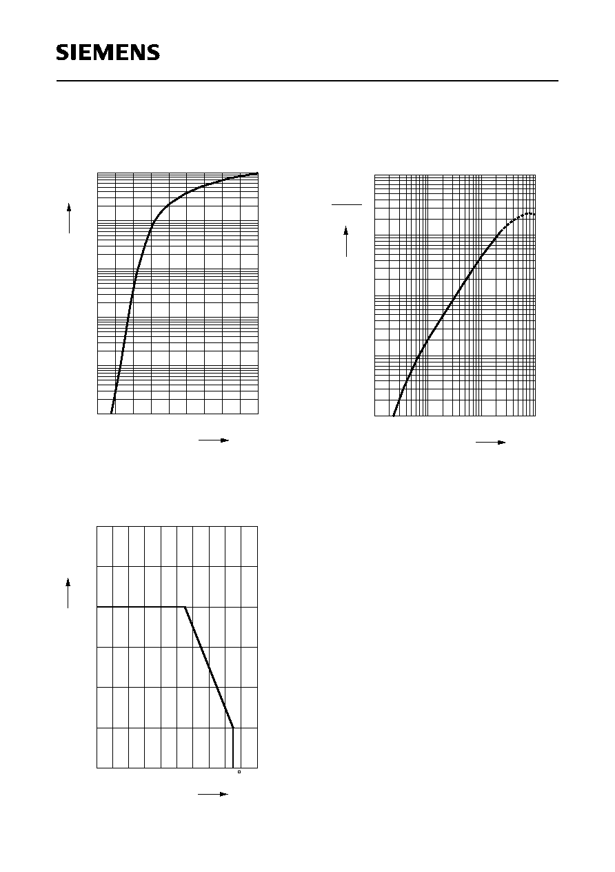
DurchlaŖstrom
I
F
=
f
(
V
F
)
Forward current
T
A
= 25 įC
Maximal zulšssiger DurchlaŖstrom
Max. permissible forward current
I
F
=
f
(
T
A
)
Relative Lichtstšrke
I
V
/
I
V(20 mA)
=
f
(
I
F
)
Relative luminous intensity
T
A
= 25 įC
10
-3
V
OHL00427
F
F
V
mA
1.4 1.6 1.8 2.0 2.2 2.4 2.6 2.8
3.2
-2
10
-1
10
0
10
1
10
2
10
F
0
0
OHL00428
A
T
5
10
15
20
25
30
mA
C
10 20 30 40 50 60 70 80
100
V
V (20 mA)
10
-1
0
10
10
1
2
10
mA
10
-3
5
OHL00426
F
5
-2
10
5
-1
10
0
10
1
10
5
5

Semiconductor Group
6
1998-08-28
LG Q971
MaŖzeichnung
(MaŖe in mm, wenn nicht anders angegeben)
Package Outlines
(Dimensions in mm, unless otherwise specified)
GEO06989
0.8
(0.4)
(1.08)
LED die
(0.3)
Resin
P.C. board
0.3
Ī0.15
(0.3)
Soldering terminal
Cathode mark
Polarity
Ī0.05
Ī0.05
1.6
Ī0.15
1.0
Soldering terminal
0.3
0.8
(1.2)
Ī0.05
Ī0.05