
Semiconductor Group
1
1997-11-01
Wesentliche Merkmale
q
Hergestellt im Schmelzepitaxieverfahren
q
Hohe Zuverl‰ssigkeit
q
Hohe Impulsbelastbarkeit
q
Gute spektrale Anpassung an
Si-Fotoempf‰nger
q
Geh‰usegleich mit SFH 309, SFH 409
Anwendungen
q
IR-Fernsteuerung von Fernseh-, Rundfunk-
und Videoger‰ten, Lichtdimmern
q
Lichtschranken bis 500 kHz
Features
q
Fabricated in a liquid phase epitaxy process
q
High reliability
q
High pulse handling capability
q
Good spectral match to silicon
photodetectors
q
Same package as SFH 309, SFH 409
Applications
q
IR remote control for hifi and TV sets, video
tape recorder, dimmers
q
Light-reflection switches (max. 500 kHz)
GaAIAs-IR-Lumineszenzdiode (880nm)
GaAIAs Infrared Emitter (880 nm)
SFH 487
Typ
Type
Bestellnummer
Ordering Code
Geh‰use
Package
SFH 487
Q62703-Q1095
3-mm-LED-Geh‰use (T1), klares violettes Epoxy-
Gie
harz, Anschl¸sse im 2.54-mm-Raster (
1
/
10
''),
Anodenkennzeichnung: k¸rzerer Anschlu
3 mm LED package (T1), violet-colored transparent
epoxy resin, solder tabs lead spacing 2.54 mm (
1
/
10
''),
anode marking: short lead
SFH 487-2
Q62703-Q2174
Ma
e in mm, wenn nicht anders angegeben/Dimensions in mm, unless otherwise specified.
fex06250
1.8
1.2
29
27
6.3
5.9
(3.5)
4.1
3.9
5.2
4.5
2.54 mm
spacing
¯3.1
¯2.9
0.8
0.4
0.6
0.4
4.0
3.6
0.6
0.4
Approx. weight 0.3 g
Chip position
Area not flat
GEX06250
0.7
0.4
Cathode
Anode
(SFH 487)
(SFH 409)

SFH 487
Semiconductor Group
2
1997-11-01
Grenzwerte (
T
A
= 25
∞
C)
Maximum Ratings
Bezeichnung
Description
Symbol
Symbol
Wert
Value
Einheit
Unit
Betriebs- und Lagertemperatur
Operating and storage temperature range
T
op
;
T
stg
≠ 55 ... + 100
∞
C
Sperrschichttemperatur
Junction temperature
T
j
100
∞
C
Sperrspannung
Reverse voltage
V
R
5
V
Durchla
strom
Forward current
I
F
100
mA
Sto
strom,
10
µ
s
Surge current
I
FSM
2.5
A
Verlustleistung
Power dissipation
P
tot
200
mW
W‰rmewiderstand, freie Beinchenl‰nge
max. 10 mm
Thermal resistance, lead length between
package bottom and PC-board max. 10 mm
R
thJA
375
K/W
Kennwerte (
T
A
= 25
∞
C)
Characteristics
Bezeichnung
Description
Symbol
Symbol
Wert
Value
Einheit
Unit
Wellenl‰nge der Strahlung
Wavelength at peak emission
I
F
= 100 mA
peak
880
nm
Spektrale Bandbreite bei 50 % von
I
max
,
I
F
= 100 mA
Spectral bandwidth at 50 % of
I
max
80
nm
Abstrahlwinkel
Half angle
±
20
Grad
deg.
Aktive Chipfl‰che
Active chip area
A
0.16
mm
2
Abmessungen der aktiven Chipfl‰che
Dimension of the active chip area
L
◊
B
L
◊
W
0.4
◊
0.4
mm
Abstand Chipoberfl‰che bis Linsenscheitel
Distance chip front to lens top
H
2.6
mm
Semiconductor Group
3
1997-11-01
SFH 487
Schaltzeiten,
I
e
von 10 % auf 90 % und von
90 % auf 10 %, bei
I
F
= 100 mA,
R
L
= 50
Switching times,
I
e
from 10 % to 90 % and
from 90 % to 10 %,
I
F
= 100 mA,
R
L
= 50
t
r
,
t
f
0.6/0.5
µ
s
Kapazit‰t
Capacitance
V
R
= 0 V,
f
= 1 MHz
C
o
25
pF
Durchla
spannung
Forward voltage
I
F
= 100 mA,
t
p
= 20 ms
I
F
= 1 A,
t
p
= 100
µ
s
V
F
1.5
(<
1.8)
3.0
(<
3.8)
V
Sperrstrom
Reverse current
V
R
= 5 V
I
R
0.01
(
1
)
µ
A
Gesamtstrahlungsflu
Total radiant flux
I
F
= 100 mA,
t
p
= 20 ms
e
25
mW
Temperaturkoeffizient von
I
e
bzw.
e
,
I
F
= 100 mA
Temperature coefficient of
I
e
or
e
,
I
F
= 100 mA
TC
I
≠ 0.5
%/K
Temperaturkoeffizient von
V
F
, I
F
= 100 mA
Temperature coefficient of
V
F
, I
F
= 100 mA
TC
V
≠ 2
mV/K
Temperaturkoeffizient von
peak
,
I
F
= 100 mA
Temperature coefficient of
peak
,
I
F
= 100 mA
TC
0.25
nm/K
Kennwerte (
T
A
= 25
∞
C)
Characteristics
Bezeichnung
Description
Symbol
Symbol
Wert
Value
Einheit
Unit
SFH 487
Semiconductor Group
4
1997-11-01
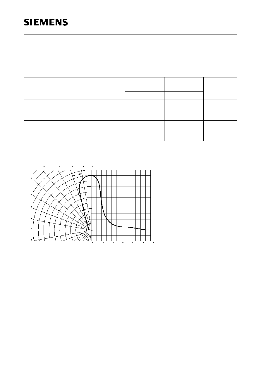
Strahlst‰rke
I
e
in Achsrichtung
gemessen bei einem Raumwinkel
= 0.01 sr
Grouping of radiant intensity
I
e
in axial direction
at a solid angle of
= 0.01 sr
Radiation characteristics
I
rel
=
f
(
)
Bezeichnung
Description
Symbol
Wert
Value
Einheit
Unit
SFH 487
SFH 487-2
Strahlst‰rke
Radiant intensity
I
F
= 100 mA,
t
p
= 20 ms
I
e
> 12.5
> 20
mW/sr
Strahlst‰rke
Radiant intensity
I
F
= 1 A,
t
p
= 100
µ
s
I
e typ.
270
270
mW/sr
OHR01895
0
20
40
60
80
100
120
0.4
0.6
0.8
1.0
100
90
80
70
60
50
0
10
20
30
40
0
0.2
0.4
0.6
0.8
1.0

Semiconductor Group
5
1997-11-01
SFH 487
Relative spectral emission
I
rel
=
f
(
)
Forward current,
I
F
=
f
(
V
F
)
Single pulse,
t
p
= 20
µ
s
0
750
rel
OHR00877
800
850
900
950 nm 1000
20
40
60
80
%
100
10
OHR00881
F
V
-3
-2
10
-1
10
0
10
1
10
0
1
2
3
4
5
6
V
8
A
F
Radiant intensity
Single pulse,
t
p
= 20
µ
s
Permissible pulse handling capability
I
F
=
f
(
),
T
A
= 25
o
C,
duty cycle
D
= parameter
I
e
I
e
100 mA
=
f
(
I
F
)
10
OHR00878
e
F
-3
-2
10
-1
10
0
10
1
10
2
10
0
10
10
1
10
2
10
4
mA
e
(100mA)
3
10
10
F
OHR00886
1
2
10
3
10
4
10
mA
-5
10
s
=
D
F
T
DC
0.005
=
D
p
t
T
t
p
p
t
0.5
0.2
0.1
0.01
0.02
0.05
10
-4
10
-3
10
-2
10
-1
10
0
10
1
10
2
Max. permissible forward current
I
F
=
f
(
T
A
)
Forward current versus lead length
between the package bottom and the
PC-board
I
F
=
f
(
I
),
T
A
= 25
o
C
T
OHR00880
0
F
0
20
40
60
80
100
∞C
mA
25
50
75
100
125
OHR00949
F
0
0
5
10
15
20
25 mm 30
20
40
60
80
100
mA
120