S8233C_E3.1_00

Seiko Instruments Inc.
1
Rev.3.1
_00
S-8233C SERIES
BATTERY PROTECTION IC (FOR A 3-SERIAL-CELL PACK)
The 8233C is a series of lithium-ion rechargeable battery protection ICs
incorporating high-accuracy voltage detection circuits and delay
circuits. The 8233C output signals according to battery voltage.
It is suitable for a 3-serial-cell lithium-ion battery pack.
Features
(1) Internal high-accuracy voltage detection circuit
Over charge detection voltage
3.80
± 0.05 V to 4.40 ± 0.05 V
5 mV - step
Over charge release voltage
3.45
± 0.10 V to 4.40 ± 0.10 V
5 mV - step
(The over charge release voltage can be selected within the range where a difference from over
charge detection voltage is 0 to 0.35 V at 50 mV - Step)
Over discharge detection voltage
2.00
± 0.08 V to 2.80± 0.08 V
50 mV - step
Over discharge release voltage
2.00
± 0.10 V to4.00± 0.10 V
50 mV - step
(The over discharge release voltage can be selected within the range where a difference from
over discharge detection voltage is 0 to 1.2V at 50 mV - Step)
Over current detection voltage 1
0.15 V
±10% to 0.50 V±10%
50 mV - step
(2) High input-voltage device (absolute maximum rating: 26 V)
(3) Indicates Li-ion battery state.
(4) Wide operating voltage range:
2 V to 24 V
(5) The delay time for every detection can be set via an external capacitor.
(6) Three over current detection levels (protection for short-circuiting)
(7) Internal charge/discharge prohibition circuit via the control terminal
(8) The function for charging batteries from 0 V is available.
(9) Low current consumption
Operation 50
µA max (+25 °C)
Power-down
0.1
µA max (+25 °C)
(10) 16-pin TSSOP package
Applications
Lithium-ion rechargeable battery packs

Battery Protection IC(for a 3-serial-cell pack)
S-8233C Series
Rev.3.1_
00
Seiko Instruments Inc.
2
Selection Guide
Table1
Model/Item Over
charge
detection voltage
Over charge
release voltage
Over discharge
detection voltage
Over discharge
release voltage
Over current
detection voltage1
0V battery
charging function
S-8233CAFT 4.25±0.05V 4.05±0.10V 2.00±0.08V 2.30±0.10V 0.25V±10%
-
Change in the detection voltage is available in products other than the above listed ones.
Contact the SII Semiconductor Products Sales Department.
Battery Protection IC(for a 3-serial-cell pack)
Rev.3.1_
00
S-8233C Series
Seiko Instruments Inc.
3
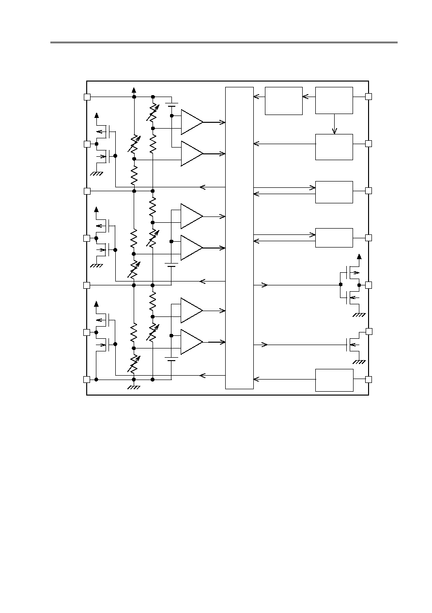
Block Diagram
Battery 1
Over charge
Battery 3
Over discharge
Battery 3
Over charge
Battery 2
Over charge
Battery 2
Over discharge
Over charge
delay circuit
Battery 1
Over discharge
Battery 3
Over charge
Battery 2
Over charge
Battery 1
Over charge
Reference
voltage 3
Reference
voltage 2
Reference
voltage 1
Control
Logic
Over current
detection
circuit
Over discharge
delay circuit
Over current,P
delay circuit
Over current
2,3 delay circuit
-
+
-
+
-
+
-
+
-
+
-
+
DOP
VMP
COVT
CDT
CCT
COP
CTL
VSS
DSO
VC2
ISO
CSO
VC1
VCC
Floating
detection circuit
Figure 1
The delay time for over current detection 2 and 3 is fixed by an internal IC circuit. The delay time
cannot be changed via an external capacitor.
1. If one of the battery voltages becomes higher than the over charge detection voltage (VCU), the
CSO terminal goes high.
2.
If one of the battery voltages becomes lower than the over discharge detection voltage (VDD), the
ISO terminal goes high.
3.
If S-8233C series detect over current, the ISO terminal goes high.
In normal state each terminal output `Low'.
Battery Protection IC(for a 3-serial-cell pack)
S-8233C Series
Rev.3.1_
00
Seiko Instruments Inc.
4
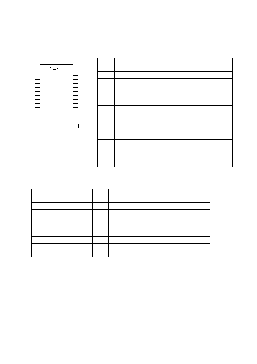
Pin Assignment
Top View
VSS
VMP
VCC
CTL
14
13
12
11
10
9
7
6
5
4
3
2
1
DOP
COP
CCT
COVT
CDT
VC1
VC2
CSO
DSO
ISO
8
15
16
NC
NC
TSSOP-16
Figure 2
Pin Description
Table2
No. Name
Description
1
DOP Connects FET gate for discharge control (CMOS output)
3
COP Connects FET gate for charge control (Nch open-drain output)
4
VMP Detects voltage between VCC to VMP(Over current detection pin)
5
COVT Connects capacitor for over current detection1delay circuit
6
CDT Connects capacitor for over discharge detection delay circuit
7
CCT Connects capacitor for over charge detection delay circuit
8
VSS Negative power input, and connects negative voltage for battery 3
9
CTL Charge/discharge control signal input
10
DSO Over discharge condition signal output
11
VC2 Connects battery 2 negative voltage and battery 3 positive voltage
12
ISO Over current condition signal output
13
VC1 Connects battery 1 negative voltage and battery 2 positive voltage
14
CSO Over voltage condition signal output
16
VCC Positive power input and connects battery 1 positive voltage
2,15 N.C.
Non
connect
Absolute Maximum Ratings
Table3
Ta = 25
°C
Item Sym.
Applied
Pins Rating
Unit
Input voltage between VCC and VSS
VDS
VSS-0.3 to VSS+26
V
Input terminal voltage
VIN
VC1,VC2,CTL,CCT,CDT,COVT VSS-0.3 to VCC+0.3
V
VMP Input terminal voltage
VVMP
VMP
VSS-0.3 to VSS+26
V
CSO,ISO,DSO output terminal voltage VOUT
CSO,ISO,DSO
VSS-0.3 to VCC+0.3
V
DOP output terminal voltage
VDOP
DOP
VSS-0.3 to VCC+0.3
V
COP output terminal voltage
VCOP
COP
VSS-0.3 to VMP+0.3
V
Power dissipation
PD
TSSOP-16PKG
300
mW
Operating temperature range
Topr
-20 to +70
°C
Storage temperature range
Tstg
-40 to +125
°C

Battery Protection IC(for a 3-serial-cell pack)
Rev.3.1_
00
S-8233C Series
Seiko Instruments Inc.
5
Electrical Characteristics
Table 4
Ta = 25°C
Item Symbol
condition
Test
circuit
Notice Min.
Typ.
Max.
Unit
Detection voltage
Over charge detection
voltage1
VCU1
1
1
4.10 to 4.35
Adjustment
VCU1-0.05 VCU1 VCU1+0.05 V
Over charge release
voltage1
VCD1
1
1
3.85 to 4.35
Adjustment
VCD1-0.10 VCD1 VCD1+0.10 V
Over discharge detection
voltage1
VDD1
1
1
2.00 to 2.70
Adjustment
VDD1-0.08 VDD1 VDD1+0.08 V
Over discharge release
voltage1
VDU1
1
1
2.00 to 3.70
Adjustment
VDU1-0.10 VDU1 VDU1+0.10 V
Over charge detection
voltage2
VCU2
2
1
4.10 to 4.35
Adjustment
VCU2-0.05 VCU2 VCU2+0.05 V
Over charge release
voltage2
VCD2
2
1
3.85 to 4.35
Adjustment
VCD2-0.10 VCD2 VCD2+0.10 V
Over discharge detection
voltage2
VDD2
2
1
2.00 to 2.70
Adjustment
VDD2-0.08 VDD2 VDD2+0.08 V
Over discharge release
voltage2
VDU2
2
1
2.00 to 3.70
Adjustment
VDU2-0.10 VDU2 VDU2+0.10 V
Over charge detection
voltage3
VCU3
3
1
4.10 to 4.35
Adjustment
VCU3-0.05 VCU3 VCU3+0.05 V
Over charge release
voltage3
VDSO
3
1
3.85 to 4.35
Adjustment
VDSO-0.10 VDSO VDSO+0.10 V
Over discharge detection
voltage3
VDD3
3
1
2.00 to 2.70
Adjustment
VDD3-0.08 VDD3 VDD3+0.08 V
Over discharge release
voltage3
VDU3
3
1
2.00 to 3.70
Adjustment
VDU3-0.10 VDU3 VDU3+0.10 V
Over current detection
voltage1
VIOV1
4
2
(*4)0.15 to 0.50V
Adjustment
VIOV1×0.9 VIOV1 VIOV1×1.1 V
Over current detection
voltage2
VIOV2 4
2
VCC
Reference 0.54 0.6 0.66 V
Over current detection
voltage3
VIOV3
4
2
VSS
Reference 1.0 2.0 3.0 V
Voltage temperature
factor 1
TCOE1
(*1)Ta=-20
to
70°C -1.0 0 1.0 mV/°C
Voltage temperature
factor 2
TCOE2
(*2)Ta=-20
to
70°C -0.5 0 0.5 mV/°C
Delay time
Over charge detection
delay time1
tCU1 9
6 CCCT=0.47
µF 0.5 1.0 1.5 S
Over charge detection
delay time2
tCU2 10
6 CCCT=0.47
µF 0.5 1.0 1.5 S
Over charge detection
delay time3
tCU3 11
6 CCCT=0.47
µF 0.5 1.0 1.5 S
Over discharge detection
delay time1
tDD1 9
6 CCDT=0.1
µF 20 40 60 mS
Over discharge detection
delay time2
tDD2 10
6 CCDT=0.1
µF 20 40 60 mS
Over discharge detection
delay time3
tDD3 11
6 CCDT=0.1
µF 20 40 60 mS
Over current detection
delay time1
tIOV1 12 7 CCOVT=0.1
µF 10 20 30 mS
Over current detection
delay time2
tIOV2
12
7
2 4 8
mS
Over current detection
delay time3
tIOV3 12 7
FET
gate
capacitor
=2000pF
100 300 550
µS
Operating voltage
Operating voltage
between VCC and VSS
VDSOP
(*3)
2.0
-
24 V
Document Outline
- S-8233C Series
- Cover
- Features
- Applications
- Selection Guide
- Block Diagram
- Pin Assignment
- Pin Description
- Absolute Maximum Ratings
- Electrical Characteristics
- Measurement Circuits
- Description
- Operation Timing Charts
- Battery Protection IC Connection Example
- Precautions
- Characteristics (typical characteristics)
- Package Drawing