
Silan
Semiconductors
SC9302 Series
HANGZHOU SILAN MICROELECTRONICS JOINT-STOCK CO.,LTD
Rev: 2.0 2001-11-01
1
1-MEMORY/2-MEMORY TONE/PULSE
DIALER
DESCRIPTION
The SC9302 series tone/pulse dialers are CMOS LSIs for the
telecommunication system. They are designed to meet various
dialing specifications through resistor options matrix.
The SC9302 series tone/pulse dialers are offered in four different
versions. They are SC9302X normal version, SC9302/F/G/H simple
version, SC9302XT key-tone version and SC9302XLT key-tone/lock
functions version. The SC9302X normal version provides the pin-
selected lock function; the SC9302XT version provides the key-tone
function; the SC9302XLT version provides both the key-tone function
and key board-operated IDD lock function. All of the above three
versions also supply the following functions: Hold-line, Hand-free and
LCD dialing number display interface, all of which are suitable for
feature phone applications. However, the SC9302F/G/H version is
simpler than the other three versions. It provides only a redialing
memory for a simple low-cost system application.
SDIP-24
SC9302D Package
FEATURES
*Universal specification
*Operating voltage: 2.0V~5.5V
*Low stand-by current
*Low memory retention current:0.1
�A(Typ.)
*Tone/pulse switchable
*Interface with LCD driver
*32 digits for redialing
*32 digits for the SA memory dialing
*One-key redialing
*Pause and P
T key for PBX
*4x4 keyboard matrix
*3.58MHz crystal or ceramic resonator
*Hand-free control
*Hold-line control
*Pause, P
T can be saved for redialing
*Lock function
*Key tone function
*Resistor options:
-M/B ratio
-Flash function and flash time
-Pause and P
T duration
-Pulse number
-Keyboard operated IDD lock function

Silan
Semiconductors
SC9302 Series
HANGZHOU SILAN MICROELECTRONICS JOINT-STOCK CO.,LTD
Rev: 2.0 2001-11-01
2
PIN CONFIGURATIONS
SC9302X NORMAL VERSION
1
2
3
4
5
6
7
8
9
18
17
16
15
14
13
12
11
10
SC9302A
R1
R2
R3
R4
HKS
DTMF
X2
V
SS
V
DD
C4
C3
C2
C1
PO
XMUTE
LOCK
X1
MODE
1
2
3
4
5
6
7
8
9
18
17
16
15
14
13
12
11
10
SC9302B
R1
R2
R3
R4
HKS
DTMF
HDO
X2
V
SS
V
DD
C4
C3
C2
C1
PO
XMUTE
LOCK
X1
MODE
22
21
20
19
HDI
HFI
HFO
1
2
3
4
5
6
7
8
9
18
17
16
15
14
13
12
11
10
SC9302C
R1
R2
R3
R4
HKS
DTMF
X2
V
SS
V
DD
C4
C3
C2
C1
PO
XMUTE
LOCK
X1
MODE
19
20
DOUT
CLOCK
1
2
3
4
5
6
7
8
9
18
17
16
15
14
13
12
11
10
SC9302D
R1
R2
R3
R4
HKS
DTMF
HDO
X2
V
SS
V
DD
C4
C3
C2
C1
PO
XMUTE
LOCK
X1
MODE
22
21
20
19
HDI
HFI
HFO
24
23
DOUT
CLOCK
SC9302A
DIP-18
SC9302D
SDIP-24
SC9302C
DIP-20
SC9302B
SDIP-22
SC9302XT/XLT VERSION
1
2
3
4
5
6
7
8
9
18
17
16
15
14
13
12
11
10
SC9302AT/ALT
R1
R2
R3
R4
HKS
DTMF
X2
V
SS
V
DD
C4
C3
C2
C1
PO
XMUTE
KT
X1
MODE
1
2
3
4
5
6
7
8
9
18
17
16
15
14
13
12
11
10
SC9302BT/BLT
R1
R2
R3
R4
HKS
DTMF
HDO
X2
V
SS
V
DD
C4
C3
C2
C1
PO
XMUTE
KT
X1
MODE
22
21
20
19
HDI
HFI
HFO
1
2
3
4
5
6
7
8
9
18
17
16
15
14
13
12
11
10
SC9302CT/CLT
R1
R2
R3
R4
HKS
DTMF
X2
V
SS
V
DD
C4
C3
C2
C1
PO
XMUTE
KT
X1
MODE
19
20
DOUT
CLOCK
1
2
3
4
5
6
7
8
9
18
17
16
15
14
13
12
11
10
SC9302DT/DLT
R1
R2
R3
R4
HKS
DTMF
HDO
X2
V
SS
V
DD
C4
C3
C2
C1
PO
XMUTE
KT
X1
MODE
22
21
20
19
HDI
HFI
HFO
24
23
DOUT
CLOCK
SC9302AT/ALT
DIP-18
SC9302DT/DLT
SDIP-24
SC9302CT/CLT
DIP-20
SC9302BT/BLT
SDIP-22

Silan
Semiconductors
SC9302 Series
HANGZHOU SILAN MICROELECTRONICS JOINT-STOCK CO.,LTD
Rev: 2.0 2001-11-01
3
SC9302F/G/H SIMPLE VERSION
1
2
3
4
5
6
7
8
9
18
17
16
15
14
13
12
11
10
SC9302F/H
R1
R2
R3
R4
HKS
DTMF
X2
V
SS
V
DD
C4
C3
C2
C1
PO
XMUTE
NC
X1
MODE
SC9302F/H
DIP-18
1
2
3
4
5
6
7
8
9
16
15
14
13
12
11
10
SC9302G
R1
R2
R3
R4
HKS
DTMF
X2
V
SS
V
DD
C3
C2
C1
PO
XMUTE
X1
MODE
SC9302G
DIP-16
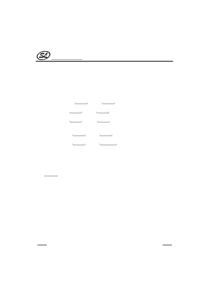
BLOCK DIAGRAM
Key
Column
Key
Row
Divider
FSM
Key
Function
Encoder
Encoder
Debounce
Clock
Generator
M/B
Clock
Control
ADDRL
WRM
Counter
Control
SRAM
Timer
Flash
Check
Tone
Encoder
Converter
Tone Out
Pulse Out
Mode In
HD/HF
Key-tone
Generater
C1
C2
C3
C4
R1
R2
R3
R4
X1
X2
LOCK
KT
MODE
HFO
HDO
HFI
HDI
HKS
XMUTE
PO
DTMF
CLOCK
DOUT

Silan
Semiconductors
SC9302 Series
HANGZHOU SILAN MICROELECTRONICS JOINT-STOCK CO.,LTD
Rev: 2.0 2001-11-01
4
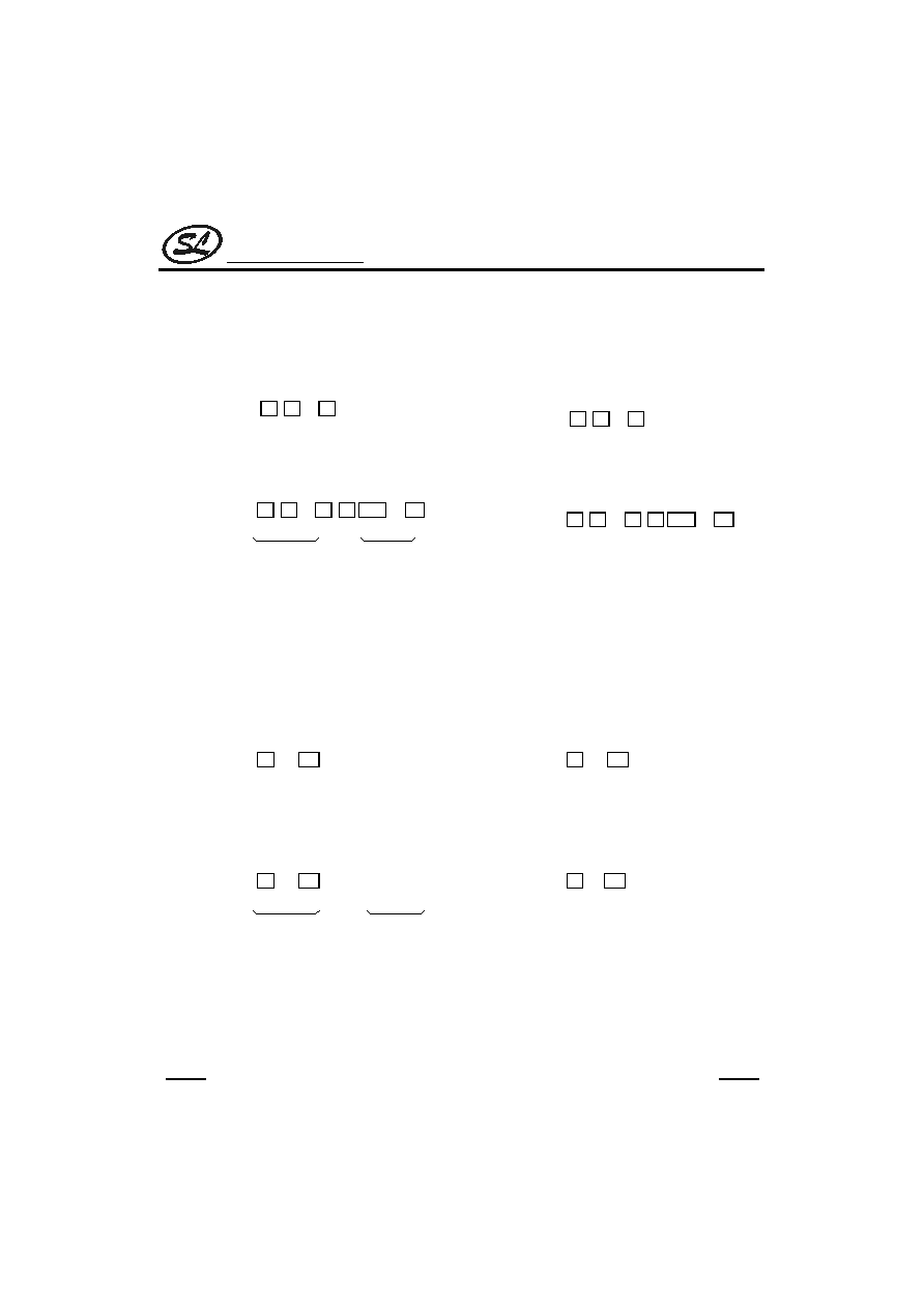
KEYBOARD INFORMATION
SA
F
P
R
3
6
9
#
2
5
8
0
1
4
7
*/T
C4
C3
C2
C1
SA
F
P
R
3
6
9
#
2
5
8
0
1
4
7
*/T
R1
R2
R3
R4
C4
C3
C2
C1
ST
HKS
R1
R2
R3
R4
F
P
R
3
6
9
#
2
5
8
0
1
4
7
*/T
C4
C3
C2
C1
R1
R2
R3
R4
F
R/P
3
6
9
#
2
5
8
0
1
4
7
*/T
C4
C3
C2
C1
R1
R2
R3
R4
F
P
R
3
6
9
#
2
5
8
0
1
4
7
*/T
C3
C2
C1
HKS
R1
R2
R3
R4
SC9302X and SC9302XT
SC9302XLT
SC9302H
SC9302F
SC9302G
Silan
Semiconductors
SC9302 Series
HANGZHOU SILAN MICROELECTRONICS JOINT-STOCK CO.,LTD
Rev: 2.0 2001-11-01
5
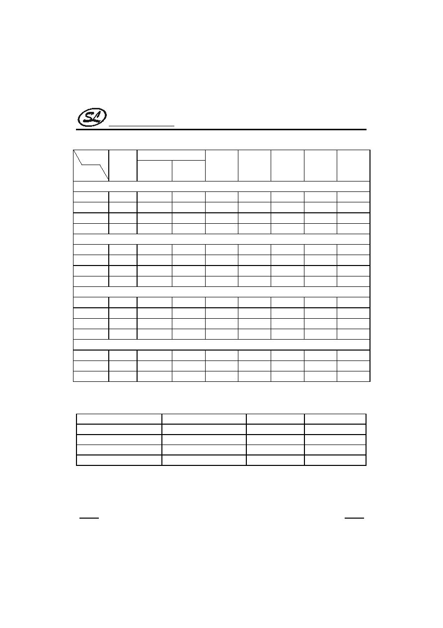
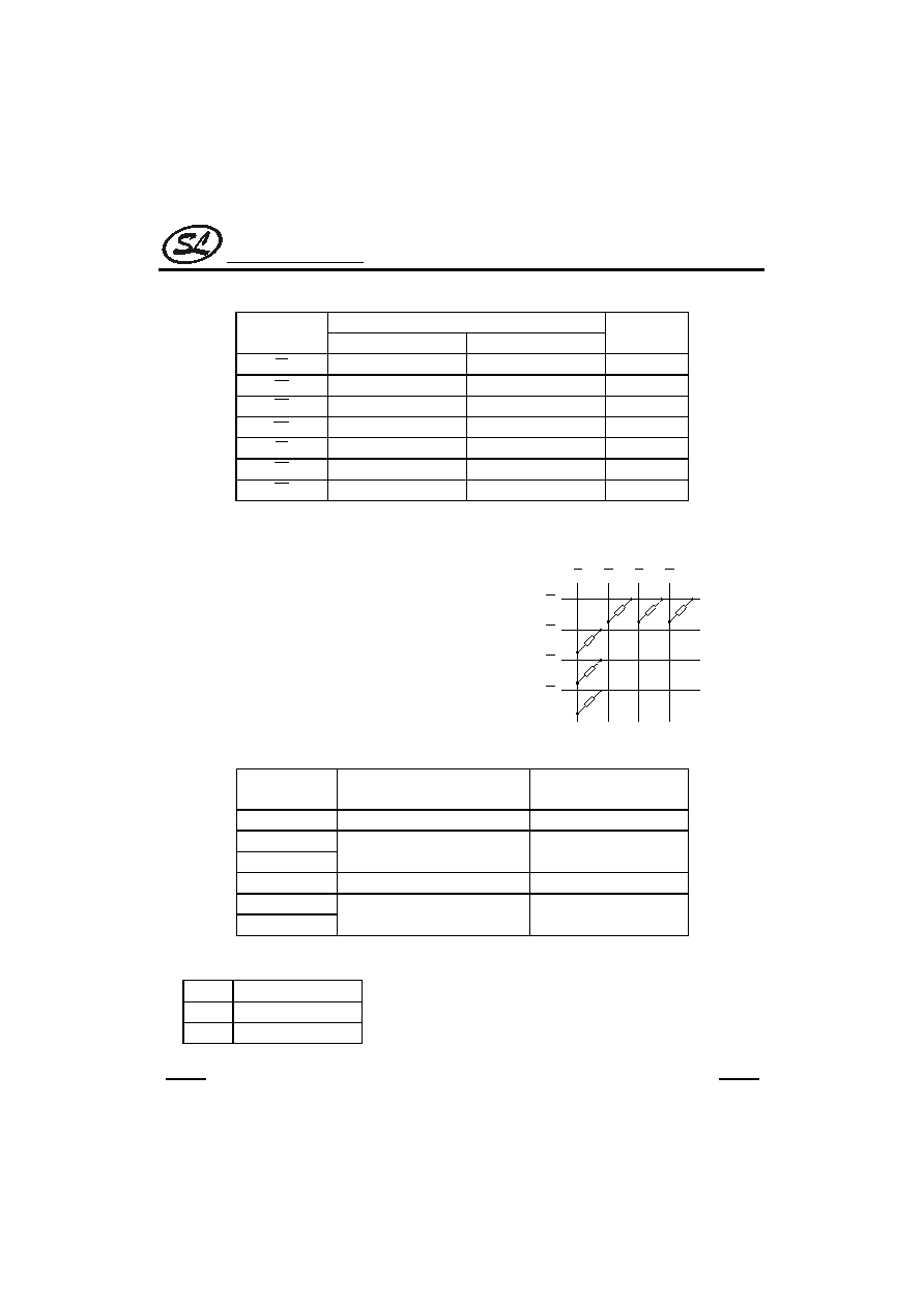
SELECTION TABLE
Function
Lock Function
Item
Keytone
Pin
Selection
Keyboard
Operated
Hold-line Hand-free
LCD
Interface
Memory
No.
Package
SC9302X (Normal version)
SC9302A
--
--
--
--
--
2
DIP-18
SC9302B
--
--
--
2
SDIP-22
SC9302C
--
--
--
--
2
DIP-20
SC9302D
--
--
2
SDIP-24
SC9302XT(Key-tone version)
SC9302AT
--
--
--
--
--
2
DIP-18
SC9302BT
--
--
--
2
SDIP-22
SC9302CT
--
--
--
--
2
DIP-20
SC9302DT
--
--
2
SDIP-24
SC9302XLT (Key-tone/Lock function version)
SC9302ALT
--
--
--
--
2
DIP-18
SC9302BLT
--
--
2
SDIP-22
SC9302CLT
--
--
--
2
DIP-20
SC9302DLT
--
2
SDIP-24
SC9302F/G/H (Simple version)
SC9302F
--
--
--
--
--
--
1
DIP-18
SC9302G
--
--
--
--
--
--
1
DIP-16
SC9302H
--
--
--
--
--
--
1
DIP-18
ABSOLUTE MAXIMUM RATINGS
(Tamb=25
�C, fosc=3.5795MHz,unless otherwise specified)
Characteristic
Symbol
Value
Unit
Supply Voltage
V
DD
-0.3 ~ 5.5
V
Input Voltage
V
IN
Vss-0.3V ~ V
CC
+0.3V
V
Operating Temperature
Topr
-20 ~ +75
�C
Storage Temperature
Tstg
-50 ~ +125
�C
Silan
Semiconductors
SC9302 Series
HANGZHOU SILAN MICROELECTRONICS JOINT-STOCK CO.,LTD
Rev: 2.0 2001-11-01
6
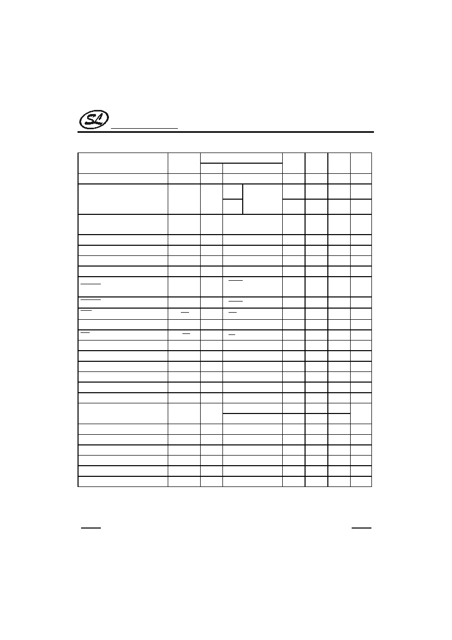
ELECTRICAL CHARACTERISTICS
(Tamb=25
�C, fosc=3.5795MHz,unless otherwise specified)
Test Conditions
Parameter
Symbol
V
DD
Condition
Min
Typ
Max
Unit
Operating Voltage
V
DD
--
--
2
--
5.5
V
Pulse
--
0.2
1
mA
Operating Current
I
DD
2.5V
Tone
Off-hook
Keypad entry
No load
--
0.6
2
mA
Stand-by Current
I
STB
1V
On-hook, no load,
No entry
--
--
1
�A
Memory Retention Voltage
V
R
--
--
1
--
5.5
V
Memory Retention Current
I
R
1V
On-hook
--
0.1
0.2
�A
Input Low Voltage
V
IL
--
--
Vss
--
0.2 V
DD
V
Input High Voltage
V
IH
--
--
0.8 V
DD
--
V
DD
V
XMUTE Leakage current
I
XMO
--
V
XMUTE
=12V,
No entry
--
--
1
�A
XMUTE Sink Current
I
OLXM
2.5V V
XMUTE
=0.5V
1
--
--
mA
HKS
Pin Input Current
I
HKS
2.5V V
HKS
=2.5V
--
--
0.1
�A
HFI Pull-Low Resistance
R
HFI
2.5V V
HFI
=2.5V
--
200
--
k
HDI Pull-High Resistance
R
HDI
2.5V V
HDI
=0V
--
200
--
k
Keypad Pin Source Current
I
OH1
2.5V V
OH
=0V
-4
--
-40
�A
Keypad Pin Sink Current
I
OL1
2.5V V
OL
=2.5V
200
400
--
�A
HFO Pin Source Current
I
OH2
2.5V V
OH
=2V
-1
--
--
mA
HFO Pin Sink Current
I
OL2
2.5V V
OL
=0.5V
1
--
--
mA
HDO Pin Source Current
I
OH3
2.5V V
OH
=2V
-1
--
--
mA
HDO Pin Sink Current
I
OL3
2.5V V
OL
=0.5V
1
--
--
mA
Control key
--
0.2
--
Pause Time After Flash
T
FP
--
Digit key
--
1
--
s
One-key Redialing Pause Time
T
RP
--
One-key redialing
--
1
--
s
Key-in Debounce Time
T
DB
--
--
--
20
--
ms
Break Time for One-key Redialing
T
BRK
--
One-key redialing
--
1.2
--
s
Key-tone Duration
T
KT
--
--
34
--
--
ms
Key-tone Frequency
F
KTC
--
--
1.2
--
--
KHz
System Frequency
Fosc
--
Crystal =3.5795MHz
3.5759 3.5795 3.5831
MHz

Silan
Semiconductors
SC9302 Series
HANGZHOU SILAN MICROELECTRONICS JOINT-STOCK CO.,LTD
Rev: 2.0 2001-11-01
7
PULSE MODE ELECTRICAL CHARACTERISTICS
(Tamb=25
�C, fosc=3.5795MHz,unless otherwise specified)
Test Conditions
Parameter
Symbol
V
DD
Condition
Min
Typ
Max
Unit
PO Output Source Current
I
POH
2.5V V
OH
=2V
-0.2
--
--
mA
PO Output Sink Current
I
POL
2.5V V
OL
=0.5V
0.2
0.6
--
mA
MODE pin is
connected to V
DD
--
10
--
Pulse Rate
PR
--
MODE pin is opened.
--
20
--
pps
A resistor is linked
between
2
R and 1
C .
--
33:66
--
Make/Break Ratio
M/B
--
No resistor is linked
between
2
R and 1
C .
--
40:60
--
%
M/B ratio =40:60
--
40(10pps)
20(20pps)
--
Pre-digit-pause Time
T
PDP
--
M/B ratio =33:66
--
33(10pps)
17(20pps)
--
ms
Pulse rate =10pps
--
800
--
Inter-digit-pause Time
T
IDP
--
Pulse rate =20pps
--
500
--
ms
A resistor is linked
between
2
R and 1
C .
--
33(10pps)
17(20pps)
--
Pulse Make Duration
T
M
--
No resistor is linked
between
2
R and 1
C .
--
40(10pps)
20(20pps)
--
ms
A resistor is linked
between
2
R and 1
C .
--
66(10pps)
33(20pps)
--
Pulse Break Duration
T
B
--
No resistor is linked
between
2
R and 1
C .
--
60(10ps)
30(20pps)
--
ms

Silan
Semiconductors
SC9302 Series
HANGZHOU SILAN MICROELECTRONICS JOINT-STOCK CO.,LTD
Rev: 2.0 2001-11-01
8
TONE MODE ELECTRICAL CHARACTERISTICS
(Tamb=25
�C, fosc=3.5795MHz,unless otherwise specified)
Test Conditions
Parameter
Symbol
V
DD
Condition
Min
Typ
Max
Unit
DTMF Output DC Level
V
TDC
--
--
0.45V
DD
--
0.7V
DD
V
DTMF Sink Current
I
TOL
2.5V V
DTMF
=0.5V
0.1
--
--
mA
DTMF Output AC Level
V
TAC
--
Row group, R
L
=5k
0.12
0.155
0.18
Vrms
DTMF Output Load
R
L
2.5V THD
-23dB
5
--
--
k
Column Pre-emphasis
A
CR
2.5V Row group = 0dB
1
2
3
dB
Tone Signal Distortion
THD
2.5V R
L
=5k
--
-30
-23
dB
Others
--
82.5
--
Minimum Tone Duration
T
TMIN
--
Auto-redial
9302G
--
100
--
ms
Others
--
85.5
--
Minimum Inter-tone Pause
T
ITPM
--
Auto-redial
9302G
--
106
--
ms
THD (Distortion)(dB)=20log
)
V
+
V
/
V
+
...
+
V
+
V
(
2
h
2
i
2
n
2
2
2
1
Vi, Vh: Row group and column group signals
V
1
,V
2
, ...Vn: Harmonic signals (BW=300Hz~3500Hz)
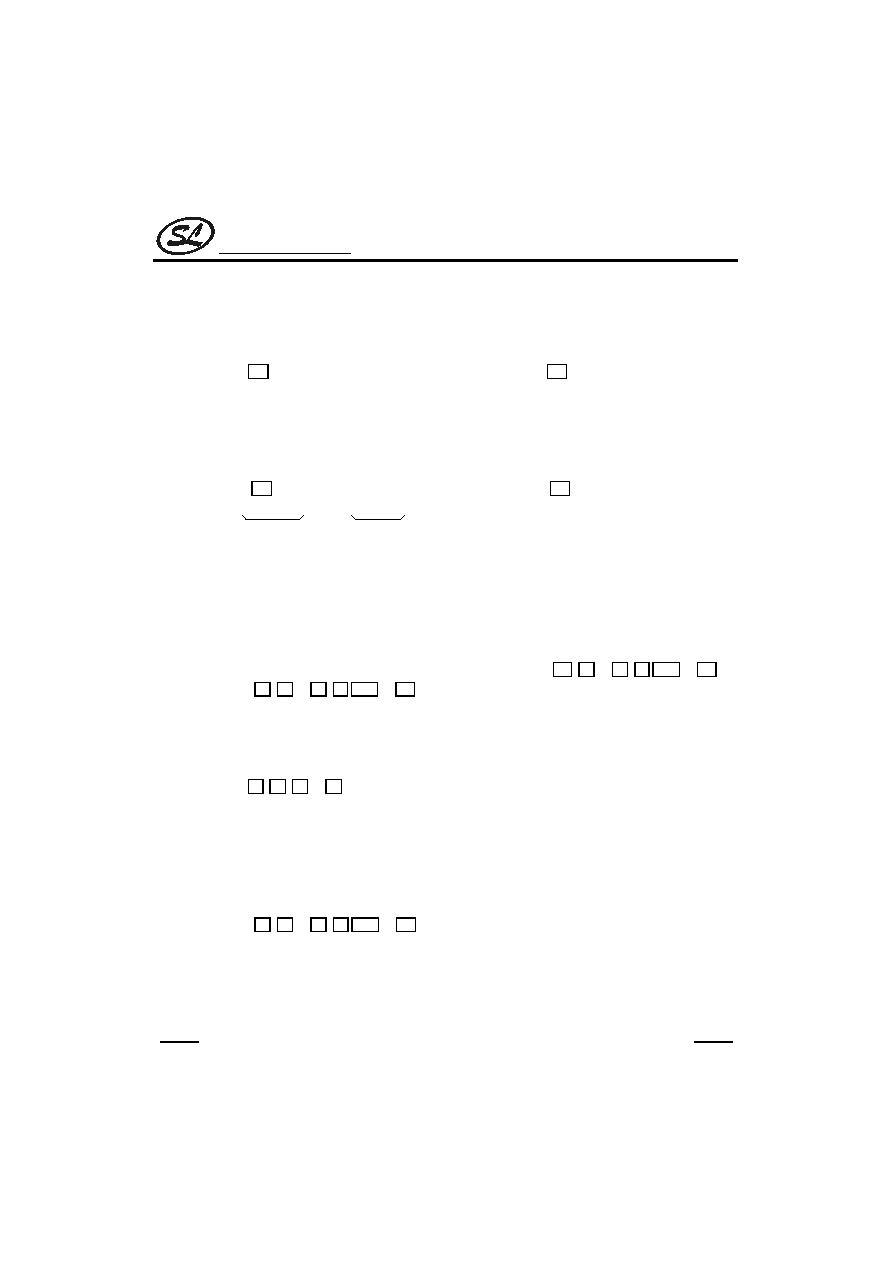
APPROXIMATE INTERNAL CONNECTION CIRCUITS
NMOS OUT
CMOS IN/OUT
V
DD
CMOS IN
CMOS OUT
V
DD
CMOS IN
Pull-High
V
DD
CMOS IN
Pull-Low
EN
10pF
20pF
10M
X1
X2
OSCILLATOR
Silan
Semiconductors
SC9302 Series
HANGZHOU SILAN MICROELECTRONICS JOINT-STOCK CO.,LTD
Rev: 2.0 2001-11-01
9
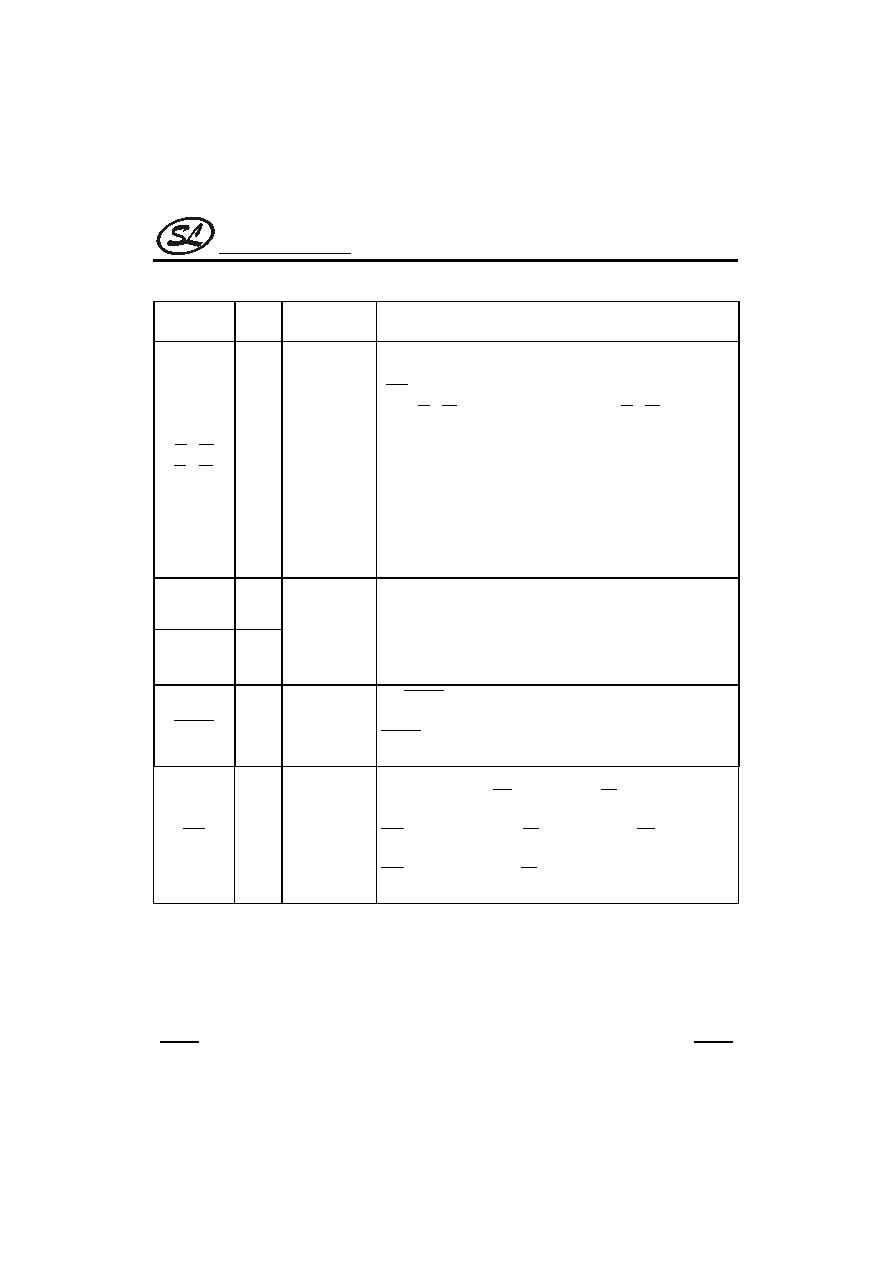
PIN DESCRIPTION
Pin Name
I/O
Internal
Connection
Description
1
C ~ 4
C
1
R ~ 4
R
I/O
CMOS
IN/OUT
These pins construct a 4x4 keyboard matrix to perform the keyboard
input detecting and dialing specification setting functions, when on-hook
(
HKS =high) all the pins are set to high. While off-hook the column
group (
1
C ~ 4
C ) stays low and the row group (
1
R ~ 4
R ) is set to high
for key input detecting.
An inexpensive single contact 4x4 keyboard can be an input device.
Pressing a key connects a single column to a single row, and actuates
the system oscillator to result in a dialing signal output. If more than two
keys are pressed at the same time, no response can be brought about.
The key-in debounce time is 20ms. Refer to the keyboard table for
keyboard arrangement and to the functional description for dialing
specification selection.
X1
I
X2
O
OSCILLATOR
The system oscillator consists of an inverter, a bias resistor and the
necessary load capacitor on chip. Connecting a standard 3.579545MHz
crystal or ceramic resonator to X1 and X2 terminals can implement the
oscillator function. The oscillator is turned off in the stand-by mode, and
is actuated whenever a keyboard entry is detected.
XMUTE
O
NMOS OUT
The
XMUTE is an NMOS open drain structure pulled to V
SS
during
dialing signal transmitting. Otherwise, it is an open circuit. The
XMUTE is used to mute the speech circuit when transmitting the dial
signal.
HKS
I
CMOS IN
This pin is used to monitor the status of the hook-switch and its
combination with HFI/
HDI can control the PO pin output to make or
break the line.
HKS =V
DD
: On-hook state (
PO =low). Except HFI/
HDI (hand-free
/ hold-line control input), other functions are all disabled.
HKS =V
SS
: Off-hook state (
PO =high). The chip is in the stand-by
mode and ready to receive the key input.
(to be continued)

Silan
Semiconductors
SC9302 Series
HANGZHOU SILAN MICROELECTRONICS JOINT-STOCK CO.,LTD
Rev: 2.0 2001-11-01
10
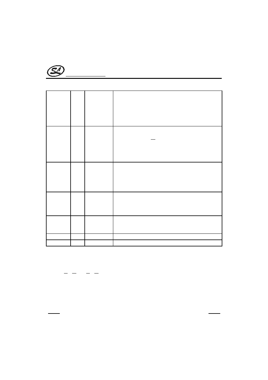
(continued)
PO
O
CMOS OUT
This pin is a CMOS output structure, it receives
HKS and HFO/HDO
signals to control the dialer so as to connect or disconnect the
telephone line.
PO outputs low to break line when
HKS is high (on-hook) and
HFO/HDO is low.
PO outputs high to make line when
HKS is low (off-
hook) or HFO is high or HDO is high.
During the off-hook state, the pin also outputs the dialing pulse train in
pulse mode dialing. While in the tone mode, this pin is always high.
MODE
I/O
CMOS
IN/OUT
This is a three-state input/output pin, provided to the user for selecting a
dialing mode among Tone/20pps/10pps.
MODE=V
DD
: Pulse mode, 10pps.
MODE=OPEN: Pulse mode, 20pps.
MODE=V
SS
: Tone mode.
During the pulse mode dialing, switching this pin to the tone mode
changes the following entrance of digits to the tone mode. When the
chips are working in the tone mode, the switching from tone to the pulse
mode will be recognized.
DTMF
O
CMOS OUT
This pin is active only when the chip transmits tone dialing signals.
Otherwise, it always outputs low. The pin outputs tone signals to drive
the external transmitter amplifier circuit. The load resistor should not be
less than 5k
.
HDI
I
CMOS IN
Pull-High
This pin is a schmitt trigger input structure. Active low. Applying a
negative going pulse to this pin can toggle the HDO output once.
An external RC network is recommended to use for the input
debouncing. The pull-high resistance is 200k
typically.
HDO
O
CMOS OUT
The HDO is a CMOS output structure. Its output is toggle controlled by
a negative transition on
HDI . When HDO is toggled to high, PO keeps
high to hold the line. The hold function can be released by setting HFO
high or by an on-off hook operation or by another
HDI input. The HDO
pin can directly drive the melody generator to produce hold-line
background melody. Refer to the functional description for the hold-line
function.
KT
O
CMOS OUT
Key-tone output pin. It outputs 1.2kHz tone carrier when any key is
pressed in the pulse mode or when the function keys are pressed in the
tone mode.
(to be continued)
Silan
Semiconductors
SC9302 Series
HANGZHOU SILAN MICROELECTRONICS JOINT-STOCK CO.,LTD
Rev: 2.0 2001-11-01
11
(continued)
HFI
I
CMOS IN
Pull-Low
This pin is a schmitt trigger input structure. Active high. Applying a
positive going pulse to HFI can toggle the HFO once and hence control
the hand-free function. The pull-low resistance of HFI is 200K
typically.
An external RC network is recommended to use for the input
debouncing.
HFO
O
CMOS OUT
The HFO is a CMOS output structure. Its output is toggle controlled by
a positive transition on HFI pin. When HFO is high, the hand-free
function is enabled and
PO outputs high to connect the line.
The hand-free function can be released by setting HDO high or by an
on-off-hook operation or by another HFI input. Refer to the functional
description for the hand-free functional operation.
LOCK
I/O
CMOS IN/OUT
This is a three-state input/output pin, provided to the user for controlling
the long distance call function with a lock-switch.
LOCK=OPEN: Normal dialing (no lock).
LOCK=V
DD
: "0,9" is inhibited for use as the first key input.
LOCK=V
SS
: "0" is inhibited for use as the first key input.
DOUT
O
NMOS OUT
This is an NMOS open drain output pin. It outputs the BCD code of the
dialing digits to the LCD driver chip (SC16XX series) or
�C for dialing
number display. Refer to the functional description for the detailed
timing.
CLOCK
O
NMOS OUT
NMOS open drain output. When dialing, it outputs a series of pulse train
for the D
OUT
data synchronization. The D
OUT
data is valid at the falling
edge of clock.
V
DD
I
--
Positive power supply, 2.0V~5.5V for normal operation.
V
SS
I
--
Negative power supply.
FUNCTION DESCRIPTIONS
1. KEYBOARD MATRIX
The
1
C ~ 4
C and
1
R ~ 4
R make up of a keyboard matrix. Together with a standard 4x4 keyboard, the
keyboard matrix is used for dialing entrance. In addition, the keyboard matrix provides resistor option for different
dialing specification selections. The keyboard arrangement for each of the SC9302 series are listed in KEYBOARD
INFORMATION.
Silan
Semiconductors
SC9302 Series
HANGZHOU SILAN MICROELECTRONICS JOINT-STOCK CO.,LTD
Rev: 2.0 2001-11-01
12
2.TONE FREQUENCY
Output Frequency (Hz)
Tone
Name
Specified
Actual
%Error
1
R
697
699
+0.29%
2
R
770
766
-0.52%
3
R
852
847
-0.59%
4
R
941
948
+0.74%
1
C
1209
1215
+0.50%
2
C
1336
1332
-0. 30%
3
C
1477
1472
-0. 34%
% Error does not contain the crystal frequency drift.
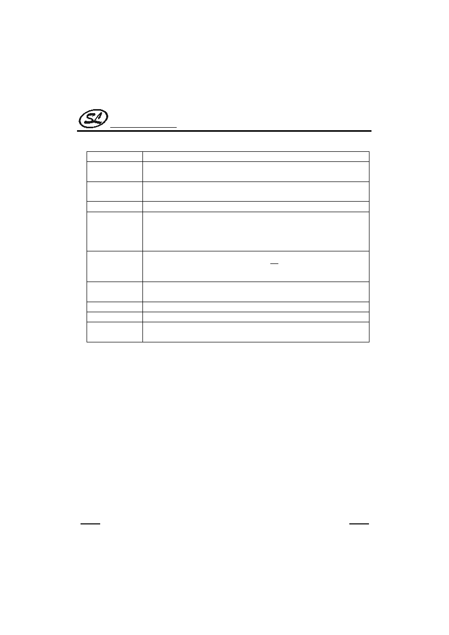
3. DIALING SPECIFICATION SELECTION
By means of adding resistors across keyboard matrix
pins, various dialing specifications can be selected. The
allowable option resistor connections are shown right.
C4
C3
C2
C1
R1
R2
R3
R4
R
K21
R
K31
R
K41
R
K12
R
K13
R
K14
All the resistors are 330k
. The resistor option functions and the default specifications (without option resistors)
are listed below.
Option
Resistor
Option Function
Default (No Resistor)
R
K12
Make/Break Ratio Selection
40:60
R
K13
R
K14
Flash Function And Flash Time
Selection
Flash = control function
Flash time = 600ms
R
K21
Pause & P
T Duration Selection
T
P
= 3.6s , T
P T
= 3.6s
R
K31
R
K41
Pulse Number Selection Or IDD
Lock Selection
N or Keyboard operated
lock
4. M/B RATIO SELECTION TABLE
R
K13
M/B Ratio(%)
No
40:60
Yes
33.3:66.6

Silan
Semiconductors
SC9302 Series
HANGZHOU SILAN MICROELECTRONICS JOINT-STOCK CO.,LTD
Rev: 2.0 2001-11-01
13
5. FLASH FUNCTION/TIME(DURATION) SELECTION TABLE
R
K13
R
K14
Flash Function
Flash
Time
(TF)
No
No
Control
600ms
No
Yes
Digit
600ms
Yes
No
Digit
98ms
Yes
Yes
Digit
300ms
6. PAUSE AND P
T DURATION SELECTION TABLE
R
K21
T
P
(sec)
T
P T
(sec)
No
3.6
3.6
Yes
2
1
7. PULSE NUMBER SELECTION TABLE
� This table shows pulse number selections for SC9302X AND SC9302XT. The table for SC9302XLT is used to
select IDD lock function.
R
K31
R
K41
Pulse Number
No
No
N
No
Yes
N + 1
Yes
No
10-N
Yes
Yes
--
� SC9302G has different selection method listed in the table below.
R
K31
Pulse Number
No
N
Yes
10-N

Silan
Semiconductors
SC9302 Series
HANGZHOU SILAN MICROELECTRONICS JOINT-STOCK CO.,LTD
Rev: 2.0 2001-11-01
14
8. PULSE NUMBER TABLE
Keypad
Output Pulse Number
Digit Key
Normal N
New Zealand (10-N)
Sweden/Denmark(N+1)
1
1
9
2
2
2
8
3
3
3
7
4
4
4
6
5
5
5
5
6
6
6
4
7
7
7
3
8
8
8
2
9
9
9
1
10
0
10
10
1
*/T
P
T
P
T
P
T
#
Ignored
Ignored
Ignored
9. HAND-FREE FUNCTION OPERATION
� Hand-free function table
Current State
Input
Next State
HKS
HFO
HDO
HDI
HFI
HKS
HFO
HDO
H
L
X
H
L
An
L
An
H
L
X
H
An
H
L
H
H
X
H
An
L
An
H
X
L
H
L
L
L
L
L
L
X
H
L
An
L
An
L
L
X
H
An
H
L
L
H
L
H
An
L
An
L
X
X
H
L
H
An
An
X
X
L
L
An
L
H
H: Logic HIGH
X: Don't care
L: Logic LOW
An: Unchanged
: Rising edge
: Falling edge

Silan
Semiconductors
SC9302 Series
HANGZHOU SILAN MICROELECTRONICS JOINT-STOCK CO.,LTD
Rev: 2.0 2001-11-01
15
� Hand-free function execution
When HFO is low, a rising edge triggers the HFI, asserting the Hand-free function (HFO becomes high).
� Reset Hand-free function
When HFO is high, the Hand-free function is enabled and can be reset by:
* Off-hook
* Applying a rising edge to HFI
* Changing the HDO pin from low to high
10. HOLD-LINE FUNCTION OPERATION
� Hold-line function execution
When HDO is low, a falling edge triggers the
HDI , asserting the Hold-line function (HDO becomes high). The
XMUTE remains low when HDO is high.
� Reset Hold-line function
When HDO is high, the Hold-line function is enabled and can be reset by:
* Off-hook.
* Applying a falling edge to
HDI .
* Changing the HFO pin from low to high.
� Hold-line function table
Current State
Input
Next State
HKS
HDO
HFO
HFI
HDI
HKS
HDO
HFO
H
L
X
L
H
An
L
An
H
L
X
L
An
H
L
H
H
L
L
An
L
An
H
X
X
L
H
L
L
L
L
L
X
L
H
An
L
An
L
L
X
L
An
H
L
L
H
L
L
An
L
An
L
X
X
L
H
H
An
An
X
X
L
H
An
L
H
H: Logic HIGH
X: Don't care
L: Logic LOW
An: Unchanged
: Rising edge
: Falling edge

Silan
Semiconductors
SC9302 Series
HANGZHOU SILAN MICROELECTRONICS JOINT-STOCK CO.,LTD
Rev: 2.0 2001-11-01
16
11. DOUT BCD CODE
When dialing, the corresponding 4-bit BCD codes are serially presented on DOUT from MSB to LSB. The data of
the DOUT is valid at the falling edge of the CLOCK pin. The following table lists the BCD codes corresponding to the
keyboard input.
Key-In
BCD Code
Key-In
BCD Code
1
0001
8
1000
2
0010
9
1001
3
0011
0
1010
4
0100
*/T
1101
5
0101
#
1100
6
0110
F
1011
7
0111
P
1110
12. LOCK FUNCTION
The function aims to detect locked dialing number to prevent a long distance call. The dialing output of the chip is
disabled if the first input key after on-off-hook is the locked number when the lock function is enabled. The lock
function selection is listed below.
The SC9302X version is the pin-selected type; on the other hand, the SC9302XLT is the key-board operated type.
However, the SC9302XT version does not support any lock function.
� SC9302X VERSION
LOCK Pin
Function
OPEN
Normal dialing (no lock)
V
DD
"0, 9" is inhibited
Vss
"0" is inhibited
� SC9302XLT VERSION
R
K31
R
K41
Function
No
No
Keyboard operated IDD lock
No
Yes
Lock 0
Yes
No
Lock 0,9
Yes
Yes
All keys are locked
Silan
Semiconductors
SC9302 Series
HANGZHOU SILAN MICROELECTRONICS JOINT-STOCK CO.,LTD
Rev: 2.0 2001-11-01
17
13. KEY DEFINITION
Key Name
Function
0,1,2,3,4,5,6,7,8,9
numerical keys
These are dialing number input keys for both the pulse mode and the tone mode
operations.
*/T
This key executes the P
T function and waits a T
P T
duration in the pulse mode. On
the other hand, the */T key executes the * function in the tone mode.
#
This is a dialing signal key for the tone mode only, no response in the pulse mode.
SA
Pressing this key can save the preceding dialing telephone numbers. The saved
number is redialed if it is pressed again. SA will also redial the saved number if it is the
first key depressed at the off-hook state. During the dialing signal transmission, the SA
key is inhibited.
F
The flash key can be selected as a digit or a control key by the option resistors
R
K13
&R
K14
. Pressing the flash key will force the
PO pin to be "low" for the T
F
duration
and is then followed by T
FP
(sec). TF can also be selected by R
K13
, R
K14
.
P
Pause key. The execution of the pause key pauses the output for the T
P
duration. T
P
can be selected by R
K21
.
R
Redial key. It executes the redialing as well as one-key redial function.
ST
This key can store lock number with personal code in IDD lock operation.
R/P
Redial and pause function key. If it is pressed as the first key after off-hook, this key
executes the redial function. Otherwise, it works as the pause key.
Silan
Semiconductors
SC9302 Series
HANGZHOU SILAN MICROELECTRONICS JOINT-STOCK CO.,LTD
Rev: 2.0 2001-11-01
18
14. KEYBOARD OPERATION
The following operations are all described under an on-off-hook or on-hook with the hand-free active condition.
� NORMAL DIALING
---Pulse Mode
a) without */T
Keyboard input: D1 D2 ... Dn
Dialing output: D1 D2 ... Dn
RM: D1 D2 ... Dn
SAM: Unchanged
b) with */T
Keyboard input: D1 D2 ... Dn */T Dn
+1
... Dm
Dialing output: D1 D2 ... Dn T
P T
Dn
+1
...Dm
Pulse Tone
RM: D1 D2 ... Dn */T Dn
+1
...Dm
SAM: Unchanged
---Tone Mode
a) without */T
Keyboard input: D1 D2 ... Dn
Dialing output: D1 D2 ... Dn
RM: D1 D2 ... Dn
SAM: Unchanged
b) with */T
Keyboard input: D1 D2 ... Dn */T Dn
+1
... Dm
Dialing output: D1 D2 ... Dn * Dn
+1
...Dm
RM: D1 D2 ... Dn * Dn
+1
...Dm
SAM: Unchanged
Note : The maximum capacity of the RM memory is 32 digits. When over 32 digits are entered, the signal is
transmitted but the redial function is inhibited.
� REDIAL
---Pulse Mode
a) without */T
RM content: D1 D2 ... Dn
Keyboard input: R (or R/P)
Dialing output: D1 D2 ... Dn
RM: Unchanged
SAM: Unchanged
b) with */T
RM content: D1 D2 ... Dn */T Dn
+1
...Dm
Keyboard input: R (or R/P)
Dialing output: D1 D2 ... Dn T
P T
Dn
+1
...Dm
Pulse Tone
RM: Unchanged
SAM: Unchanged
---Tone Mode
a) without */T
RM content: D1 D2 ... Dn
Keyboard input: R (or R/P)
Dialing output: D1 D2 ... Dn
RM: Unchanged
SAM: Unchanged
b) with */T
RM content: D1 D2 ... Dn */T Dn
+1
...Dm
Keyboard input: R (or R/P)
Dialing output:
D1 D2 ... Dn * Dn
+1
...Dm
RM: Unchanged
SAM: Unchanged

Silan
Semiconductors
SC9302 Series
HANGZHOU SILAN MICROELECTRONICS JOINT-STOCK CO.,LTD
Rev: 2.0 2001-11-01
19
� ONE-KEY REDIAL
---Pulse Mode
a) without */T
Keyboard input: D1 D2 ... Dn R
Dialing output: D1 D2 ... Dn T
BRK
T
RP
D1 D2 ... Dn
RM: D1 D2 ... Dn
SAM: Unchanged
b) with */T
Keyboard input: D1 D2 ... Dn */T Dn
+1
... Dm R
Dialing output: D1 D2 ... Dn T
P T
Dn
+1
...Dm T
BRK
Pulse Tone
T
RP
D1 D2 ... Dn T
P T
Dn
+1
...Dm
Pulse Tone
RM: D1 D2 ... Dn */T Dn
+1
...Dm
SAM: Unchanged
---Tone Mode
a) without */T
Keyboard input: D1 D2 ... Dn R
Dialing output: D1 D2 ... Dn T
BRK
T
RP
D1 D2 ... Dn
RM: D1 D2 ... Dn
SAM: Unchanged
b) with */T
Keyboard input: D1 D2 ... Dn */T Dn
+1
... Dm R
Dialing output: D1 D2 ... Dn * Dn
+1
...Dm T
BRK
T
RP
D1 D2 ... Dn *
Dn
+1
...Dm
RM: D1 D2 ... Dn * Dn
+1
...Dm
SAM: Unchanged
Note: If the dialing number is over 32 digits, the redialing is inhibited and
PO = V
DD
.
� SA COPY
---Pulse Mode
a) without */T
Keyboard input: D1 D2 ... Dn SA
Dialing output: D1 D2 ... Dn
RM: D1 D2 ... Dn
SAM: D1 D2 ... Dn
b) with */T
Keyboard input: D1 D2 ... Dn */T Dn
+1
... Dm SA
Dialing output: D1 D2 ... Dn T
P T
Dn
+1
...Dm
Pulse Tone
RM: D1 D2 ... Dn */T Dn
+1
...Dm
SAM: D1 D2 ... Dn */T Dn
+1
...Dm
---Tone Mode
a) without */T
Keyboard input: D1 D2 ... Dn SA
Dialing output: D1 D2 ... Dn
RM: D1 D2 ... Dn
SAM: D1 D2 ... Dn
b) with */T
Keyboard input: D1 D2 ... Dn */T Dn
+1
... Dm SA
Dialing output: D1 D2 ... Dn * Dn
+1
...Dm
RM: D1 D2 ... Dn * Dn
+1
...Dm
SAM: D1 D2 ... Dn * Dn
+1
...Dm
Note: The maximum capacity of the RM memory is 32 digits. When over 32 digits plus the "SA" key are entered, the
SAVE function will not be executed, and all the existing data in the save memory will not be changed.
Silan
Semiconductors
SC9302 Series
HANGZHOU SILAN MICROELECTRONICS JOINT-STOCK CO.,LTD
Rev: 2.0 2001-11-01
20
� SA DIALING
---Pulse Mode
a) without */T
SAM content: D1 D2 ... Dn
Keyboard input: SA
Dialing output: D1 D2 ... Dn
RM: Unchanged
SAM: Unchanged
b) with */T
SAM content: D1 D2 ... Dn */T Dn
+1
...Dm
Keyboard input: SA
Dialing output: D1 D2 ... Dn T
P T
Dn
+1
...Dm
Pulse Tone
RM: Unchanged
SAM: Unchanged
---Tone Mode
a) without */T
SAM content: D1 D2 ... Dn
Keyboard input: SA
Dialing output: D1 D2 ... Dn
RM: Unchanged
SAM: Unchanged
b) with */T
SAM content: D1 D2 ... Dn * Dn
+1
...Dm
Keyboard input: SA
Dialing output: D1 D2 ... Dn * Dn
+1
...Dm
RM: Unchanged
SAM: Unchanged
� FLASH
---Flash as a digital key
a) The intervenient key
Keyboard input: D1 D2 ... Dn F Dn
+1
... Dm
Dialing output: D1 D2 ... Dn T
F
T
FP
Dn
+1
...Dm
RM: D1 D2 ... Dn
SAM: Unchanged
b) The first key
Keyboard input: F D1 D2 ... Dn
Dialing output:
T
F
T
FP
D1 D2 ... Dn
RM: Unchanged
SAM: Unchanged
---Flash as a control key
Keyboard input: D1 D2 ... Dn F Dn
+1
... Dm
Dialing output: D1 D2 ... Dn T
F
T
FP
Dn
+1
...Dm
RM: Dn
+1
...Dm
SAM: Unchanged
Note: T
F
: break a flash time
� PAUSE
Keyboard input: D1 D2 ... Dn P Dn
+1
... Dm
Dialing output: D1 D2 ... Dn T
P
Dn
+1
...Dm
RM: P Dn
+1
...Dm
SAM: Unchanged
� NOTE
RM: Redial memory
SAM: Save dialing memory
D1 D2 ... Dn: 0~9
Dn
+1
...Dm: 0~9, *, #
Silan
Semiconductors
SC9302 Series
HANGZHOU SILAN MICROELECTRONICS JOINT-STOCK CO.,LTD
Rev: 2.0 2001-11-01
21
� IDD lock operation by the keyboard (2 lock numbers, 3 digits/number at maximum)
---Personal / lock No.1 / Lock No.2 input operation
a) Personal code doesn't exist
Stores Personal Code: ST D1 D2 D3 ST * 0
Stores Lock No.1: ST D4 D5 D6 ST * 1
Stores Lock No.2: ST D7 D8 D9 ST * 2
b) Personal code exist
Changes Personal Code: ST D1 D2 D3 ST # ST D4 D5 D6 ST * 0
(Old personal code) (New personal code)
Changes Lock No.1: ST D1 D2 D3 ST # ST D4 D5 D6 ST * 1
(personal code) (Lock No.1)
Changes Lock No.2: ST D1 D2 D3 ST # ST D7 D8 D9 ST * 2
(personal code) (Lock No.2)
Changes Personal Code, Lock No.1 and Lock No.2 at one time
ST D1 D2 D3 ST # ST D4 D5 D6 ST * 0 (continued)
(Old personal code) (New personal code)
ST D7 D8 D9 ST # ST D10 D11 D12 ST * 2
(Lock No.1) (Lock No.2)
---Personal / lock No.1 / Lock No.2 cancel operation
Cancels Personal Code: ST D1 D2 D3 ST # ST # 0
Cancels Lock No.1: ST D1 D2 D3 ST # ST # 1
Cancels Lock No.2: ST D1 D2 D3 ST # ST # 2
---Temporary release both of the lock numbers (Lock No.1, Lock No.2):
ST D1 D2 D3 ST # Dm Dm+1 Dm+2 Dl...Dn
(Personal code)
Note: D1~D12=0~9
Dm Dm+1 Dm+2 = 0~9
Dl...Dn = 0~9, *, #
� Note:
RM: Redial memory
SAM: Save dialing memory
D1 D2...Dn: 0~9
Dn+1...Dm: 0~9, *, #
Dm+1...Dl: 0~9, *, #
Dl+1...Dk: 0~9, *, #

Silan
Semiconductors
SC9302 Series
HANGZHOU SILAN MICROELECTRONICS JOINT-STOCK CO.,LTD
Rev: 2.0 2001-11-01
22
OPERATION TIMING
1. NORMAL DIALING
�
PULSE MODE
HKS
KEY IN
XMUTE
PO
T
DB
D1
D2
R
T
PDP
T
IDP
T
M
T
KT
20ms
20ms
1.2KHz Carrier
XMUTE
DTMF
KT
X2
High impedance
T
DB
T
DB
T
IDP
-T
M
T
IDP
-T
M
T
PDP
T
IDP
-T
M
T
KT
T
IDP
-T
M
T
KT
Others
SC9302G
�
TONE MODE
HKS
KEY IN
XMUTE
PO
T
DB
D1
D2
R
20ms
20ms
DTMF
KT
X2
High impedance
T
ITPM
T
TMIN
T
DB
T
ITPM
T
ITPM
T
ITPM

Silan
Semiconductors
SC9302 Series
HANGZHOU SILAN MICROELECTRONICS JOINT-STOCK CO.,LTD
Rev: 2.0 2001-11-01
23
2. DIALING WITH PAUSE KEY
�
PULSE MODE
HKS
KEY IN
XMUTE
Others
PO
T
D
B
D1
D2
P
T
P
+T
PDP
T
IDP
T
PDP
T
KT
20ms
1.2KHz carrier
XMUTE
SC9302G
DTMF
KT
X2
High impedance
D3
T
M
T
IDP
-T
M
T
KT
T
M
T
IDP
-T
M
�
TONE MODE
HKS
KEY IN
XMUTE
PO
T
DB
20ms
DTMF
KT
X2
High impedance
T
ITPM
T
TMIN
D1
D2
P
D3
T
P
T
ITPM
T
ITPM

Silan
Semiconductors
SC9302 Series
HANGZHOU SILAN MICROELECTRONICS JOINT-STOCK CO.,LTD
Rev: 2.0 2001-11-01
24
3. FLASH KEY OPERATION
HKS
KEY IN
XMUTE
PO
T
D
B
20ms
DTMF
KT
X2
High impedance
T
F
F
T
FP
T
K
T
1.2KHz Carrier
4. PULSE
TONE OPERATION
D1
D2
*/T
D3
HKS
KEY IN
XMUTE
PO
T
D
B
20ms
DTMF
KT
X2
High impedance
T
K
T
1.2KHz Carrier
T
PD
P
T
IDP
+T
PDP
T
ID
P
T
P--
>T
T
TMI
N
T
ITP
M

Silan
Semiconductors
SC9302 Series
HANGZHOU SILAN MICROELECTRONICS JOINT-STOCK CO.,LTD
Rev: 2.0 2001-11-01
25
5. ONE KEY REDIAL OPERATION
D1
D2
R
HKS
KEY IN
XMUTE
PO
T
D
B
20ms
DTMF
KT
X2
High impedance
T
K
T
T
ITP
M
T
BRK(2 secs)
T
RP
(1 secs)
T
D
B
T
ITP
M
T
D
B
T
ITP
M
T
ITP
M
6. CLOCK & DOUT OPERATION
D1
HKS
KEY IN
XMUTE
PO
T
D
B
20ms
CLOCK
DOUT
X2
High impedance
KT
T
PD
P
T
B
T
M
T
KT
(34ms)
1.2kHz Carrier
F
CLOCK
=2.4kH
z
Data
Note: D1=D3=3, D2=2.
Silan
Semiconductors
SC9302 Series
HANGZHOU SILAN MICROELECTRONICS JOINT-STOCK CO.,LTD
Rev: 2.0 2001-11-01
26
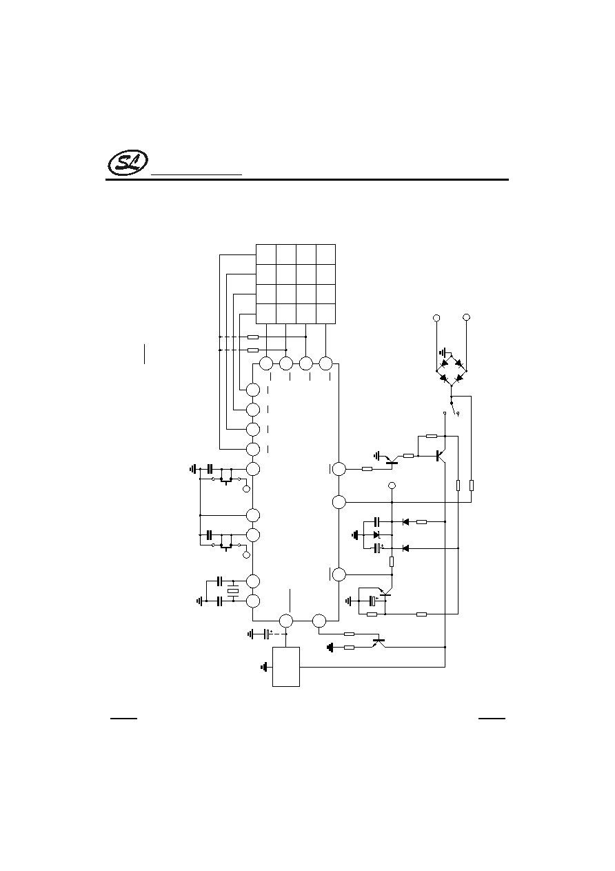
TYPICAL APPLICATIONS
1. SC9302A (DIP-18)
HKS
V
DD
C4
C3
C2
C1
PO
XMUTE
15
16
17
18
SA
F
P
R
3
6
9
#
2
5
8
0
1
4
7
*/T
1
2
3
4
R4
R3
R2
R1
5
0,9
No lock
0
V
SS
LOCK
9
VD
D
10pps
Tone
14
MODE
20pps
10pF
10pF
6
7
X1
X2
39pF
39pF
3.58MHz
resonator
SPEECH
NETWORK
8
1�F
13
DTMF
1A Bridge
Tip
Ring
11
10
12
V
DD
0.1�F
100�F
RK
RK
100k
47k
VD
D
3.3k
22M
100K
2.2k
IN4148
IN4148
5.1V
270k
Hook off
Hook on
1�F
100k
200k
1.5k
150
A42
A92
SC9302A (DIP-18)
* R
K
for dialing signal option. (Refer to the functional description)
* Unmarked transistors are of 8050 type.
* A 1
�
F capacitor between
XMUTE
and Vss (GND) is recommended.

Silan
Semiconductors
SC9302 Series
HANGZHOU SILAN MICROELECTRONICS JOINT-STOCK CO.,LTD
Rev: 2.0 2001-11-01
27
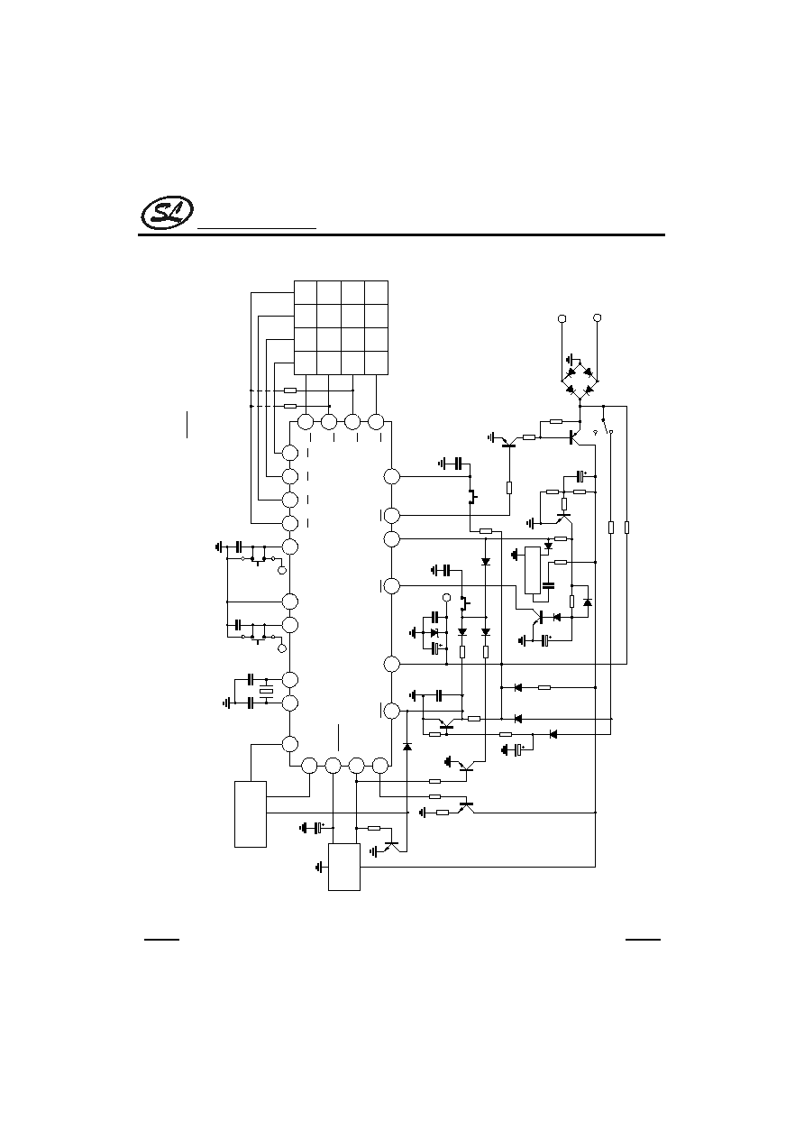
2. SC9302B (SDIP-22)
HKS
V
DD
C4
C3
C2
C1
PO
XMUTE
21
18
19
20
SA
F
P
R
3
6
9
#
2
5
8
0
1
4
7
*/T
6
2
3
4
R4
R3
R2
R1
5
0,9
No lock
0
V
SS
LOCK
10
VD
D
10pps
Tone
17
MODE
20pps
10pF
10pF
7
8
X1
X2
39pF
39pF
3.58MHz
resonator
12
16
DTMF
1
22
V
DD
RKRK
150
SC9302B (SDIP-22)
9
SPEECH
NETWORK
1�F
HFO
14
Melody IC
13
11
15
Hook off
Hook on
1A Bridge
Tip
Ring
HDI
HDO
HFI
1.5k
47k
100k
1�F
270k
0.1�F
220k
IN4148
IN4148
2.2k
100�F
5.1V
0.1�F
VD
D
0.1�F
22k
22k
Hold
1�F
16V
IN4148
330k
IN4148x4
0.1�F
4.7k
220k
33k
100k
10�F
50V
10k
Handfree
A42
3.3k
A92
100k
220k
100k
22M
0.02�F
* R
K
for dialing signal option. (Refer to the functional description)
* Unmarked transistors are of 8050 type.
* A 1
�
F capacitor between
XMUTE
and Vss (GND) is recommended.
* The melody IC provides a melody during the hold period.

Silan
Semiconductors
SC9302 Series
HANGZHOU SILAN MICROELECTRONICS JOINT-STOCK CO.,LTD
Rev: 2.0 2001-11-01
28
3. SC9302C(DIP-20)
HKS
V
DD
C4
C3
C2
C1
PO
XMUTE
17
18
19
20
SA
F
P
R
3
6
9
#
2
5
8
0
1
4
7
*/T
1
2
3
4
R4
R3
R2
R1
5
0,9
no lock
0
V
SS
LOCK
9
VD
D
10pps
Tone
16
MODE
20pps
10pF
10pF
6
7
X1
X2
39pF
39pF
3.58MHz
resonator
8
15
DTMF
1A Bridge
Tip
Ring
13
12
14
V
DD
0.1�F
100�F
R
K
R
K
100k
47k
VD
D
3.3k
22M
100K
2.2k
IN4148
IN4148
5.1V
270k
Hook off
Hook on
1�F
100k
200k
1.5k
150
A42
A92
SC9302C (DIP-20)
SC16XX
LCD DRIVER
(see SC16XX data)
10
11
SPEECH
NETWORK
1�F
CLOCK
DOUT
IN4148
* R
K
for dialing signal option. (Refer to the functional description)
* Unmarked transistors are of 8050 type.
* A 1
�
F capacitor between
XMUTE
and Vss (GND) is recommended.
Silan
Semiconductors
SC9302 Series
HANGZHOU SILAN MICROELECTRONICS JOINT-STOCK CO.,LTD
Rev: 2.0 2001-11-01
29
4. SC9302D (SDIP-24)
HKS
VD
D
C4
C3
C2
C1
PO
XMUTE
23
20
21
22
SA
F
P
R
3
6
9
#
2
5
8
0
1
4
7
*/T
6
2
3
4
R4
R3
R2
R1
5
0,9
no lock
0
V
SS
LOCK
10
VDD
10pps
Tone
19
MODE
20pps
10pF
10pF
7
8
X1
X2
39pF
39pF
3.58MHz
resonator
12
9
DTMF
1
24
V
DD
RK
RK
150
SC9302D (SDIP-24)
13
SPEECH
NETWORK
HFO
16
Melody IC
15
11
17
Hook off
Hook on
1A Bridge
Tip
Ring
HDI
HDO
HFI
1.5k
47k
100k
1�F
270k
0.1�F
220k
IN4148
IN4148
2.2k
100�F
5.1V
0.1�F
VD
D
0.1�F
22k
22k
Hold
1�F
16V
IN4148
330k
IN4148x4
0.1�F
4.7k
220k
33k
100k
10�F
50V
47k
Handfree
A42
3.3k
A92
100k
220k
100k
22M
0.02�F
14
18
1�F
SC16XX
LCD DRIVER
(see SC16XX data)
DOUT
CLOCK
IN4148
47k
* R
K
for dialing signal option. (Refer to the functional description)
* Unmarked transistors are of 8050 type.
* A 1
�
F capacitor between
XMUTE
and Vss (GND) is recommended.
* The Melody IC provides a melody during the hold period.

Silan
Semiconductors
SC9302 Series
HANGZHOU SILAN MICROELECTRONICS JOINT-STOCK CO.,LTD
Rev: 2.0 2001-11-01
30
5. SC9302AT/ALT (DIP-18)
HKS
C4
C3
C2
C1
PO
XMUTE
15
16
17
18
SA
F
P
R
3
6
9
#
2
5
8
0
1
4
7
*/T
1
2
3
4
R4
R3
R2
R1
5
V
SS
KT
9
VD
D
10pps
Tone
14
MODE
20pps
10pF
6
7
X1
X2
39pF
39pF
3.58MHz
resonator
SPEECH
NETWORK
8
1�F
13
DTMF
1A Bridge
Tip
Ring
11
10
12
V
DD
0.1�F
100�F
R
K
R
K
100k
47k
VD
D
3.3k
22M
100K
2.2k
IN4148
IN4148
5.1V
270k
Hook off
Hook on
1�F
100k
200k
1.5k
150
A42
A92
SC9302AT/ALT (DIP-18)
ST
To Buzzer
* R
K
for dialing signal option. (Refer to the functional description)
* Unmarked transistors are of 8050 type.
* A 1
�
F capacitor between
XMUTE
and Vss (GND) is recommended.

Silan
Semiconductors
SC9302 Series
HANGZHOU SILAN MICROELECTRONICS JOINT-STOCK CO.,LTD
Rev: 2.0 2001-11-01
31
6. SC9302BT/BLT (SDIP-22)
HKS
C4
C3
C2
C1
PO
XMUTE
21
18
19
20
SA
F
P
R
3
6
9
#
2
5
8
0
1
4
7
*/T
6
2
3
4
R4
R3
R2
R1
5
V
SS
KT
10
VD
D
10pps
Tone
17
MODE
20pps
10pF
7
8
X1
X2
39pF
39pF
3.58MHz
resonator
12
16
DTMF
1
22
V
DD
RK
RK
150
SC9302BT/BLT (SDIP-22)
9
SPEECH
NETWORK
1�F
HFO
14
Melody
13
11
15
Hook off
Hook on
1A Bridge
Tip
Ring
HDI
HDO
HFI
1.5k
47k
100k
1�F
270k
0.1�F
220k
IN4148
IN4148
2.2k
100�F
5.1V
0.1�F
V
DD
0.1�F
22k
22k
Hold
1�F
16V
IN4148
330k
IN4148x4
0.1�F
4.7k
220k
33k
100k
10�F
50V
47k
Handfree
A42
3.3k
A92
100k
220k
100k
22M
0.02�F
47k
SA
To Buzzer
* R
K
for dialing signal option. (Refer to the functional description)
* Unmarked transistors are of 8050 type.
* A 1
�
F capacitor between
XMUTE
and Vss (GND) is recommended.
* The Melody IC provides a melody during the hold period.

Silan
Semiconductors
SC9302 Series
HANGZHOU SILAN MICROELECTRONICS JOINT-STOCK CO.,LTD
Rev: 2.0 2001-11-01
32
7. SC9302CT/CLT (DIP-20)
HKS
C4
C3
C2
C1
PO
XMUTE
17
18
19
20
SA
F
P
R
3
6
9
#
2
5
8
0
1
4
7
*/T
1
2
3
4
R4
R3
R2
R1
5
V
SS
KT
9
VD
D
10pps
Tone
16
MODE
20pps
10pF
6
7
X1
X2
39pF
39pF
3.58MHz
resonator
8
15
DTMF
1A Bridge
Tip
Ring
13
12
14
V
DD
0.1�F
100�F
RK
R
K
100k
47k
VD
D
3.3k
22M
100K
2.2k
IN4148
IN4148
5.1V
270k
Hook off
Hook on
1�F
100k
200k
1.5k
150
A42
A92
SC9302CT/CLT (DIP-20)
SC16XX
LCD DRIVER
(see SC16XX data)
10
11
SPEECH
NETWORK
1�F
CLOCK
DOUT
IN4148
ST
To Buzzer
* R
K
for dialing signal option. (Refer to the functional description)
* Unmarked transistors are of 8050 type.
* A 1
�
F capacitor between
XMUTE
and Vss (GND) is recommended.

Silan
Semiconductors
SC9302 Series
HANGZHOU SILAN MICROELECTRONICS JOINT-STOCK CO.,LTD
Rev: 2.0 2001-11-01
33
8. SC9302DT/DLT (SDIP-24)
HKS
C4
C3
C2
C1
PO
XMUTE
23
20
21
22
SA
F
P
R
3
6
9
#
2
5
8
0
1
4
7
*/T
R4
R3
R2
R1
V
SS
KT
VD
D
10pps
Tone
MODE
20pps
10pF
X1
X2
39pF
39pF
3.58MHz
resonator
14
18
DTMF
1
24
V
DD
RK
RK
150
SC9302DT/DLT (SDIP-24)
9
SPEECH
NETWORK
1�F
HFO
16
Melody IC
15
11
17
Hook off
Hook on
1A Bridge
Tip
Ring
HDI
HDO
HFI
1.5k
47k
100k
1�F
270k
0.1�F
220k
IN4148
IN4148
2.2k
100�F
5.1V
0.1�F
VD
D
0.1�F
22k
22k
Hold
1�F
16V
IN4148
330k
IN4148x4
0.1�F
4.7k
220k
33k
100k
10�F
50V
47k
Handfree
A42
3.3k
A92
100k
220k
100k
22M
0.02�F
47k
SA
To Buzzer
CLOCK
12
DOUT
6
2
3
4
5
10
19
7
8
13
SC16xx
LCD DRIVER
(see SC16xx data)
* R
K
for dialing signal option. (Refer to the functional description)
* Unmarked transistors are of 8050 type.
* A 1
�
F capacitor between
XMUTE
and Vss (GND) is recommended.
* The Melody IC provides a melody during the hold period.

Silan
Semiconductors
SC9302 Series
HANGZHOU SILAN MICROELECTRONICS JOINT-STOCK CO.,LTD
Rev: 2.0 2001-11-01
34
9. SC9302H (DIP-18)
HKS
C4
C3
C2
C1
PO
XMUTE
15
16
17
18
F
R/P
3
6
9
#
2
5
8
0
1
4
7
*/T
1
2
3
4
R4
R3
R2
R1
5
V
SS
NC
9
VD
D
10pps
Tone
14
MODE
20pps
10pF
6
7
X1
X2
39pF
39pF
3.58MHz
resonator
SPEECH
NETWORK
8
1�F
13
DTMF
1A Bridge
Tip
Ring
11
10
12
V
DD
0.1�F
100�F
R
K
R
K
100k
47k
VDD
3.3k
22M
100K
2.2k
IN4148
IN4148
5.1V
270k
Hook off
Hook on
1�F
100k
200k
1.5k
150
A42
A92
SC9302H (DIP-18)
* R
K
for dialing signal option. (Refer to the functional description)
* Unmarked transistors are of 8050 type.
* A 1
�
F capacitor between
XMUTE
and Vss (GND) is recommended.

Silan
Semiconductors
SC9302 Series
HANGZHOU SILAN MICROELECTRONICS JOINT-STOCK CO.,LTD
Rev: 2.0 2001-11-01
35
10. SC9302G (DIP-16)
HKS
C3
C2
C1
PO
XMUTE
13
14
15
16
F
P
R
3
6
9
#
2
5
8
0
1
4
7
*/T
1
2
3
R4
R3
R2
R1
V
SS
7
VD
D
10pps
Tone
12
MODE
20pps
10pF
4
5
X1
X2
39pF
39pF
3.58MHz
resonator
SPEECH
NETWORK
6
1�F
11
DTMF
1A Bridge
Tip
Ring
9
8
10
V
DD
0.1�F
100�F
R
K
R
K
100k
47k
VDD
3.3k
22M
100K
2.2k
IN4148
IN4148
5.1V
270k
Hook off
Hook on
1�F
100k
200k
1.5k
150
A42
A92
SC9302G (DIP-16)
* R
K
for dialing signal option. (Refer to the functional description)
* Unmarked transistors are of 8050 type.
* A 1
�
F capacitor between
XMUTE
and Vss (GND) is recommended.

Silan
Semiconductors
SC9302 Series
HANGZHOU SILAN MICROELECTRONICS JOINT-STOCK CO.,LTD
Rev: 2.0 2001-11-01
36
11. SC9302F (DIP-18)
HKS
C4
C3
C2
C1
PO
XMUTE
15
16
17
18
F
P
R
3
6
9
#
2
5
8
0
1
4
7
*/T
1
2
3
4
R4
R3
R2
R1
5
V
SS
NC
9
VD
D
10pps
Tone
14
MODE
20pps
10pF
6
7
X1
X2
39pF
39pF
3.58MHz
resonator
SPEECH
NETWORK
8
1�F
13
DTMF
1A Bridge
Tip
Ring
11
10
12
V
DD
0.1�F
100�F
RKR
K
100k
47k
VDD
3.3k
22M
100K
2.2k
IN4148
IN4148
5.1V
270k
Hook off
Hook on
1�F
100k
200k
1.5k
150
A42
A92
SC9302F (DIP-18)
* R
K
for dialing signal option. (Refer to the functional description)
* Unmarked transistors are of 8050 type.
* A 1
�
F capacitor between
XMUTE
and Vss (GND) is recommended.

Silan
Semiconductors
SC9302 Series
HANGZHOU SILAN MICROELECTRONICS JOINT-STOCK CO.,LTD
Rev: 2.0 2001-11-01
37
CHIP TOPOGRAPHY
19
18
17
16
15
14
13
12
11
10
9
8
7
6
5
4
3
2
1
24
23
22
21
20
Chip size: 1.90 x 1.73 mm
2
PAD COORDINATES
(Unit:
�m)
Pad No.
Symbol
X
Y
Pad No.
Symbol
X
Y
1
P1
-934.05
-225.30
13
P13
927.70
234.85
2
P2
-956.65
-503.00
14
P14
927.70
463.25
3
P3
956.65
-800.20
15
P15
890.75
619.10
4
P4
-668.20
-879.95
16
P16
937.55
839.50
5
P5
-391.80
-879.95
17
P17
761.90
875.45
6
P6
-137.60
-861.45
18
P18
363.20
875.45
7
P7
589.50
-845.65
19
P19
35.90
873.65
8
P8
846.10
-847.35
20
P20
-679.90
873.35
9
P9
899.15
-469.80
21
P21
-956.65
779.70
10
P10
954.35
-283.90
22
P22
-956.65
521.30
11
P11
927.70
-117.95
23
P23
-956.65
244.90
12
P12
927.70
71.75
24
P24
-940.35
-5.70
Note: The original point of the coordinate is the die center.
Silan
Semiconductors
SC9302 Series
HANGZHOU SILAN MICROELECTRONICS JOINT-STOCK CO.,LTD
Rev: 2.0 2001-11-01
38
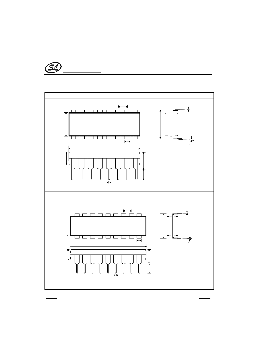
PACKAGE OUTLINE
DIP-16-300-2.54
UNIT:mm
6.40
2.54
3.51
5.08
3.30
7.62
0.25
15 degree
0.46
19.4
1.50
DIP-18-300-2.54
UNIT:mm
6.40
2.54
3.51
5.08
3.30
7.62
0.25
15 degree
0.46
22.95
1.50

Silan
Semiconductors
SC9302 Series
HANGZHOU SILAN MICROELECTRONICS JOINT-STOCK CO.,LTD
Rev: 2.0 2001-11-01
39
DIP-20-300-2.54
UNIT:mm
6.40
2.54
3.51
7.62
0.25
15 degree
0.46
22.95
1.50
5.08
3.30
SDIP-24-300-2.54
UNIT:mm
2.54
7.62
0.25
15 degree
0.46
34.50
1.50
5.08
3.30
6.40
3.51