 | –≠–ª–µ–∫—Ç—Ä–æ–Ω–Ω—ã–π –∫–æ–º–ø–æ–Ω–µ–Ω—Ç: SP3070E | –°–∫–∞—á–∞—Ç—å:  PDF PDF  ZIP ZIP |

Rev K: 0/9/06 Advanced Features of the SP3070E/SP3088E Copyright © 2006 Sipex Corporation
Overview
The SP3070-3078E and SP3080-3088E families of advanced RS-485 transceivers contain a rich
feature set designed to simplify the design of robust, high performance RS-485 communication net-
works. All members of these two new product families remain fully backward compatible to industry
standard RS-485 devices, keeping the same footprint and pin locations as earlier products. They are
ideal for new designs or as replacements in existing RS-485 or RS-422 systems.
This document describes some of the new features found on SP3070-3078E and SP3080-3088E de-
vices and is intended to help system designers understand how to use these devices most effectively.
General Description
The SP3070E-3078E and SP3080-3088E families include a total of 8 products. SP3070-3078E op-
erate from a 3.3V supply voltage and SP3080-3088E operate from 5V supplies. Each family offers a
choice of slow, medium or fast data-rates and either half-duplex, full-duplex or full-duplex with enable/
shutdown. Each device contains one differential driver and one differential receiver. All comply with
both RS-485 and RS-422 EIA Standards.
Advanced Features of the SP3070E-SP3078E and SP3080E- SP3088E High Performance
RS-485 Transceivers
Application Note ANI20
3.0 to 3.6V Supply
Type
Pins
250kbps,
Low EMI
500kbps,
Reduced EMI
6Mbps,
High Speed
Half-duplex
8
SP3072E
SP3075E
SP3078E
Full-duplex,
Low Pin-count
8
SP307E
SP3074E
SP3077E
Full-duplex,
Enable/Shutdown
4
SP3070E
SP3073E
SP3076E
4.5 to 5.5V Supply
Type
Pins
5kbps,
Low EMI
500kbps,
Reduced EMI
20Mbps,
High Speed
Half-duplex
8
SP3082E
SP3085E
SP3088E
Full-duplex,
Low Pin-count
8
SP308E
SP3084E
SP3087E
Full-duplex,
Enable/Shutdown
4
SP3080E
SP3083E
SP3086E
Tables and 2 - Product Selection Matrices
Solved by
TM

Rev K: 0/9/06 Advanced Features of the SP3070E/SP3088E Copyright © 2006 Sipex Corporation
2
Significant Features of the SP3070E-3078E and SP3080E-3088E Families
The SP3070E-3078E and SP3080-3088E families share a number of enhanced features that differen-
tiate these products from other RS-485 transceivers. Below is a list of the "Top Ten" major enhance-
ments that separate these new products from ordinary RS-485 devices.
)
/8th Unit Load
2)
Available as half-duplex, full duplex or full-duplex with enable/shutdown pins
3)
Advanced Failsafe
4)
Voltage Overload Protection
5)
Thermal Overload Protection
6)
Hot Swap and Glitch Protection
7)
Slew Rate Controlled Driver
8)
Low Power Shutdown
9)
Enhanced ESD Protection
0) Industry Standard Package Footprints
3
Rev K: 0/9/06 Advanced Features of the SP3070E/SP3088E Copyright © 2006 Sipex Corporation
1/8th Unit Load
All devices in the SP3070E-3078E and SP3080E-3088E families are /8th Unit Load transceivers.
This feature enables large RS-485 networks of up to 256 devices to operate over the full common
mode voltage range.
RS-485 is defined to allow multiple transmitters to coexist on a single segment of twisted-pair cable.
Only one transmitter may be active and driving at a time but many receivers or transceivers (with
driver off) may coexist. Receivers have high input impedance but will absorb some signal-current
from the bus. Each additional receiver or transceiver will therefore increase the loading on the driv-
ers. The number of nodes that any segment can support is therefore limited by the strength of the
drivers and the load characteristics of each receiver.
A standard RS-485 driver is capable of driving up to 32 "Unit Loads" plus two line-termination resis-
tors of 120 each. The EIA-485 standard defines Unit Load in terms of the current load over a com-
mon mode voltage range of -7V to +2V from device ground. Common mode voltage is an important
factor because at common mode further from device ground the driver must source or sink more cur-
rent into the load to maintain the same signal margin at a receiver.
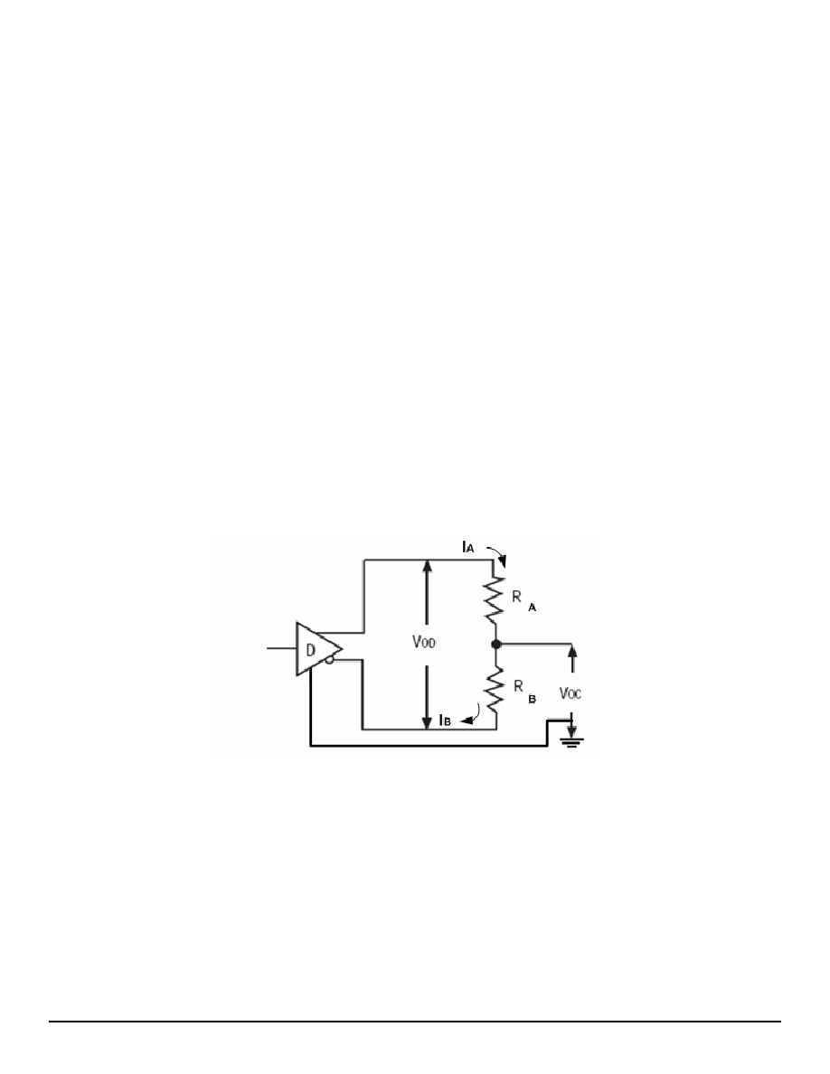
The figure below is a simplified electrical model of a driver and load. Each terminal has an input im-
pedance (RA, RB) to local ground. Local ground at the load may be offset from the driver's reference
ground by some common mode voltage VOC. The driver attempts to maintain a differential voltage
VOD across the receiver inputs. Driver current into A and B increases proportionally to the magnitude
of VOC.
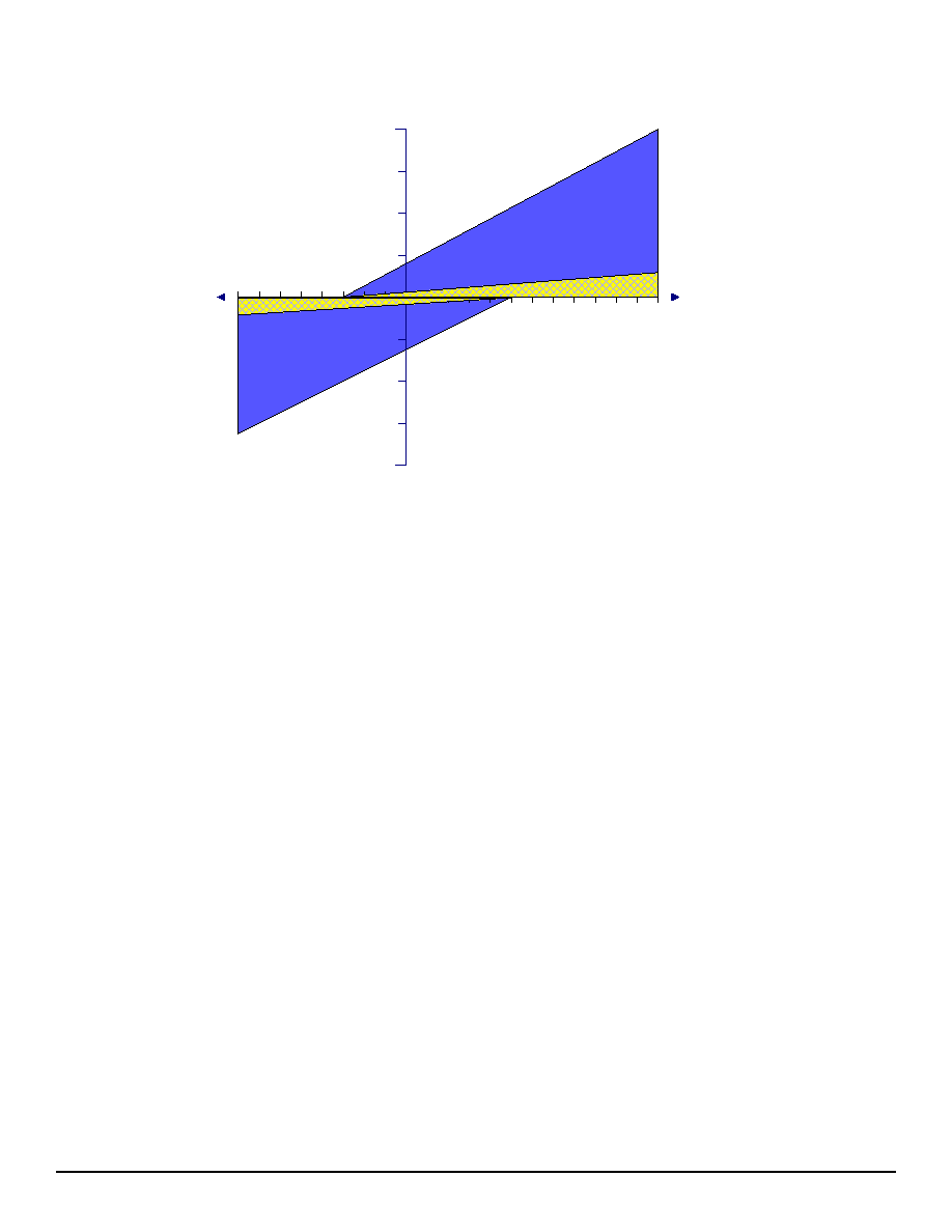
The dark shaded region in the figure below defines an RS-485 Unit Load. At +12V the current into
the load cannot exceed mA. At -7V current cannot exceed -0.8mA. A purely resistive load of
12,000 fits within this region. The actual load area extends along a 15k slope to points at -3V and
+5V, allowing for some non-linearity in the actual load.
Rev K: 0/9/06 Advanced Features of the SP3070E/SP3088E Copyright © 2006 Sipex Corporation
4
5V
12V
-3V
-7V
1mA
-0.8mA
I
Z
RS485
1 Unit Load
(shaded area)
0.125mA
-0.1mA
1/8th Unit Load
(cross-hatched)
SP3070E-3078E and SP3080E-3088E devices are /8th Unit Load. This means that over the same
input voltage range they will load a driver only /8th as much. That area is shown in the cross-
hatched area of the figure above. At +12V input the current into a 1/8th UL device cannot exceed
25uA.
Typical RS-485 receivers are one Unit Load apiece. An RS-485 driver can maintain signal to 32 unit
loads over the -7V to +2V common mode range. With /8th Unit Load devices the same driver can
support eight times the number of transceivers, up to 256.
Different types of receivers may be mixed in a network. For every Unit Load transceiver you can
substitute eight /8th UL devices. This may extend the span of existing networks.
RS-422 or V. receivers may interoperate with RS-485. However they do not support the full com-
mon mode voltage range. Also they may have a lower input impedance of 4k, meaning that each
V. or RS-422 receiver consumes approximately 3 Unit Loads.
If the common mode voltage is limited, such as by bonding the grounds of all RS-485 nodes, then it
may be possible to build very large networks of hundreds of nodes. Using /8th UL devices will fur-
ther increase the number of transceivers.
5
Rev K: 0/9/06 Advanced Features of the SP3070E/SP3088E Copyright © 2006 Sipex Corporation
2.
Full-duplex or Half-duplex operation
The SP3070E-3078E and SP3080E-3088E families include devices in half-duplex, full duplex and
full-duplex with control inputs. All devices are available in industry standard packages and pinouts.
This makes Sipex enhanced SP3070 and SP3080 series devices ideal upgrades for existing RS-485
designs.
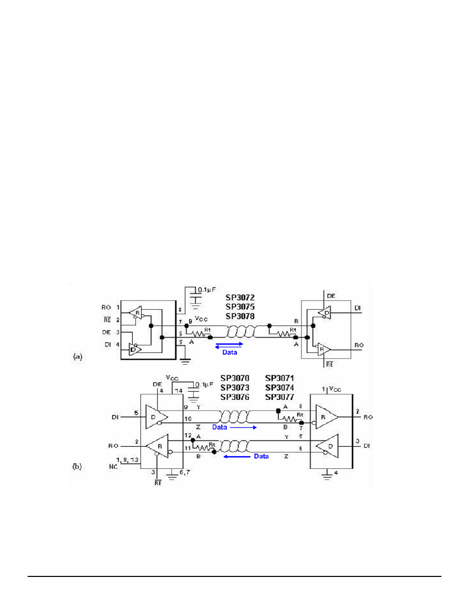
Half-Duplex is the most commonly used bus scheme for RS-485. Figure 2a shows a typical RS-485
Half Duplex data bus. As few as two or up to 32 Unit Loads, may coexist on the bus. Any node may
transmit but only one node may be driving at a time. Data travels bidirectionally on the bus.
The most significant advantage of Half-Duplex is that it requires only a single twisted-pair. This mini-
mizes cable costs. However because only one node at a time is permitted to transmit, half-duplex
operation requires bus arbitration to prevent data collisions. The RS-485 standard defines only the
electrical characteristics of the interface and does not specify arbitration techniques. Bus arbitration
is left up to the end-user. Various proprietary and open-standard interface protocols use RS-485 as a
physical media and define methodologies for bus arbitration.
Sipex SP3072E, SP3075E, SP3078E, SP3082E, SP3085E and SP3088E are configured for Half-Du-
plex operation. On these devices the data-bus pins A and B are bi-directional. Driver output enable
pin (active high) and receiver enable pin (active low) are opposite polarity and facilitate driver/receiver
control on a bidirectional data bus.
Full-Duplex (figure 2b) requires two twisted pairs.
On each wire-pair, data travels only in a single direction. The driver and receiver of each node are
physically connected to different wire-pairs. On each pair only a single driver may be active at any
given time.
This increases cabling costs but decreases complexity. Full-duplex may be configured point to point
(one driver into one receiver) or point to multipoint (one driver and many receivers). In a
: RS485 and RS422 physical topologies are explained in the Application Note ANI13. http://www.sipex.com/files/ApplicationNotes/
RS485%20Topology.pdf