
FEATURES
∑ FLAT GAIN RESPONSE FROM 5 TO 210 MHz: f =
±0.25
dB
∑ INPUT AND OUTPUT MATCHING TO 75 OHMS: R
L
= > 18 dB
∑ LOW VOLTAGE = 12V
∑ LOW CURRENT 90 mA TYP
∑ AUTOMATED SURFACE MOUNT CONSTRUCTION
PART NUMBER
ISG52124-L
SYMBOLS
PARAMETERS AND CONDITIONS
UNITS
MIN
TYP
MAX
Supply Voltage
V
12
Operating Current
mA
80
90
120
BW
Bandwidth
MHz
5
210
G
A
Gain at f = 42 MHz
dB
23.5
24
24.5
G
Gain Flatness
dB
±0.25
RL
IN
Input Return Loss
dB
18
RL
OUT
Output Return Loss
dB
18
NF
Noise Figure at f = 65 MHz
dB
4.5
5
P
1dB
Output Power at 1 dB Gain Compression Point
dBmV
70
72
CTB
Composite Triple Beat
1
(+50 dBmV/ch)
dBc
-63
-60
XM
Cross Modulation
1
(+50 dBmV/ch)
dBc
-56
-53
CSO
2nd Order Distortion
1
(+50 dBmV/ch)
dBc
-66
-62
Characteristic Impedance
ohms
75
ELECTRICAL CHARACTERISTICS
(V
CC
= 12 V, ± 10%, T
A
= 25∞C, 75 Ohm System)
Note:
1. Composite Triple Beat, Cross Modulation, 2nd Order Distortion are all measured with 7 channels (T7-T13). at 50 dBmV/ch output and at25∞C.
DESCRIPTION
The ISG52124-L is a low Power 12V Broadband hybrid amplifier
module developed for return path optical and RF applications
in (HFC) CATV systems.The ISG52124-L is comprised of 100%
surface mount components, including high performance silicon
transistors. It features excellent noise, gain, and thermal stability
across a wide range of operating conditions and frequencies.The
amplifiers are manufactured to ISO9002 standards are very
rugged and exhibit excellent unit to unit uniformity.
OUTLINE DIMENSIONS
(Units in mm [inches])
ISG52124-L
45.08 [1.775] MAX
38.10
±
0.25 [1.500
±
.010]
3.49 [.137]
14.85 [.585] MAX
2
◊
4.00
[
.157
]
THRU
+0.14
-0.24
+.006
-.009
27.30 [1.075] MAX
8.04 [.317]
3.96 [.156]
[
.315
]
+.005
-.008
+0.13
-0.20
8.00
0.51
±
0.05 [.020
±
.002]
5.08
±
0.13 [.200
±
.005]
2.54
±
0.13 [.100
±
.005]
21.08 [.830]
10.20
±
0.25 [.402
±
.010]
25.40
±
0.25 [1.000
±
.010]
17.44 [.687]
9.84 [.387]
2
◊
6-32 UNC-2B
4.20
±
0.13 [.165
±
.005]
[
.500
]
+.010
-.035
+0.25
-0.89
12.70
2
◊
[
]
+4.15
-3.85
+.163
-.152
2.54
±
0.38 [.100
±
.015]
8.60
±
0.25
[.340
±
.010]
10.75
±
0.25 [.423
±
.010]
IN
OUT
GND
V
CC
1
9
2 3
5
7 8
5 TO 210 MHz SILICON CATV
24 dB LOW POWER HYBRID AMPLIFIER
ISG52124-L
Performance tests and ratings for Sirenza Microdevices products were performed internally by Sirenza and measured using specific computer systems and/or components and reflect the
approximate performance of the products as measured by those tests. Any difference in circuit implementation, test software, or test equipment may affect actual performance. The
information provided herein is believed to be reliable at press time and Sirenza Microdevices assumes no responsibility for the use of this information. All such use shall be entirely at the
users own risk. Prices and specifications for Sirenza Microdevices products are subject to change without notice. Buyers should consult Sirenza Microdevices standard terms and
conditions of sale for Sirenzas limited warranty with regard to its products. No patent rights or licenses to any of the circuits described herein are implied or granted to any third party.
Sirenza Microdevices does not authorize or warrant any product for use in life-support devices and/or systems.
REV. A
4/1/2005
1
303 S. Technology Court, Broomfield, CO 80021 303-327-3030 www.sirenza.com
ISG52124-L
ABSOLUTE MAXIMUM RATINGS
1
(T
A
= 25 ∞C unless otherwise noted)
SYMBOLS
PARAMETERS
UNITS
RATINGS
V
CC
DC Supply
V
DC
+28
V
IN
RF Input Voltage
(Single Tone)
dBmV
+65
T
C
Operating Case
Temperature Range
∞C
-20 to +100
T
STG
Storage Temperature
Range
∞C
-40 to +100
Note:
1. Operation in excess of any one of these parameters may result
in permanent damage.
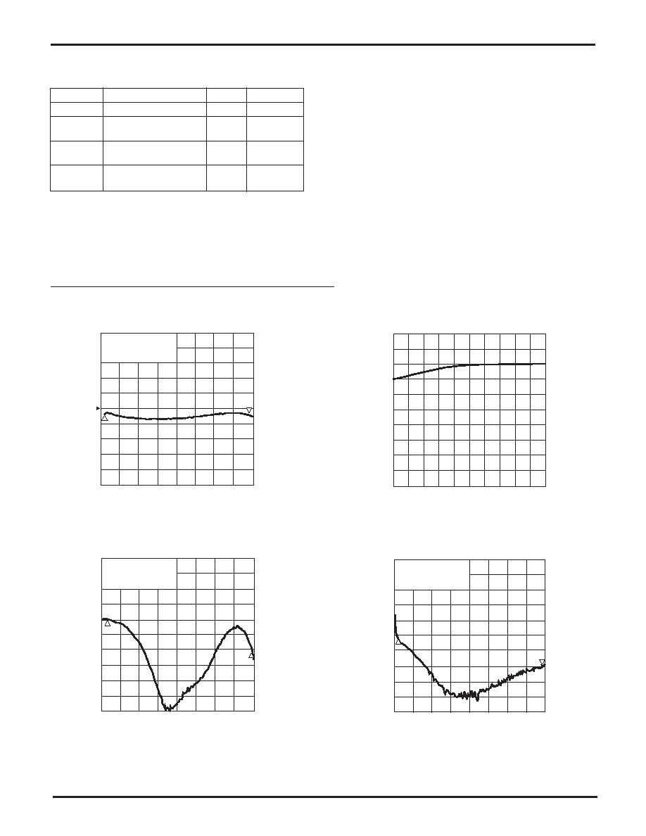
GAIN vs. FREQUENCY
NOISE FIGURE
OUTPUT RETURN LOSS
INPUT RETURN LOSS
1
Start 1.00 MHz
Stop 210.00 MHz
Marker 1
5 MHz (23.852 dB)
Marker 2
210 MHz (23.759 dB)
2
22.5
22
21.5
23
23.5
1:
24.5
25
25.5
26
26.5
-28
-30
-32
Start 5.00 MHz
Stop 210.00 MHz
-26
-24
-22
-20
-18
-16
-14
-12
Marker 1
5 MHz (-20.027 dB)
Marker 2
210 MHz (-24.869 dB)
1
2
Start 5.00 MHz
Stop 210.00 MHz
-28
-30
-32
-26
-24
-22
-20
-18
-16
-14
-12
Marker 1
5 MHz (-21.772 dB)
Marker 2
210 MHz (-25.539 dB)
1
2
TYPICAL PERFORMANCE CURVES
(T
A
= 25∞C)
START 5.0 MHz
STOP 210.00 MHz
1
1.5
2
2.5
3
3.5
4.0
4.5
5
5.5
6.0
REV. A
4/1/2005
2
303 S. Technology Court, Broomfield, CO 80021 303-327-3030 www.sirenza.com