
ST
Sitronix
ST7556
65 x 102 Dot Matrix LCD Controller/Driver
Ver 2.0 1/43 2003/11/27
1. INTRODUCTION
The ST7556 is a driver & controller LSI for graphic dot-matrix liquid crystal display systems. It contains 102 segment
and 65 common with 1 ICOM driver circuits. This chip is connected directly to a microprocessor, accepts 4-line serial
interface (SPI) or 8-bit parallel interface, display data can store in an on-chip display data RAM of 66 x 102 bits. It
performs display data RAM read/write operation with no external operating clock to minimize power consumption. In
addition, because it contains power supply circuits to drive liquid crystal, it is possible to make a display system with the
fewest components.
2. FEATURES
Driver Output Circuits
102 segment outputs / 65 common outputs
On-chip Display Data ram
-
Capacity: 66X102=6,732 bits
Microprocessor Interface
-
8-bit parallel bi-directional interface with
6800-series or 8080-series
-
4-line SPI (serial peripheral interface) available
(only write operation)
On-chip Low Power Analog Circuit
-
Generation of LCD supply voltage (externally
Vout voltage supply is possible)
-
Generation of intermediate LCD bias voltages
-
Oscillator requires no external components
(external clock also possible)
-
Voltage converter (x4)
-
Voltage regulator (temperature gradient
-0.05%/
�C
)
- Voltage
follower
-
On-chip electronic contrast control function (64
steps)
-
Liquid crystal driving voltage :
V0 -VSS = max 13 V (external power supply)
External RESB (reset) pin
Logic supply voltage range V
DD
-V
SS
-
1.7 to 3.3V
Temperature range: -40 to +85 degree

ST7556
Ver 2.0
2/43 2003/11/27
3. PAD Arrangement (COG)
Chip Size: 10,310 um � 1,150 um
Bump Pitch:
PAD NO 1 ~ 148 , 250 ~ 272 : 75.5 um (com/seg) PAD NO 149 ~ 248 : 75 um (I/O) PAD NO 148 ~ 149 : 114 um
PAD NO 248 ~ 249 : 93.5 um (Reset) PAD NO 249 ~ 250 : 95.9 um (Reset)
Bump Size:
PAD NO 1 ~ 125 , 137 ~ 248 , 250 ~ 261 : 55(x) um � 60(y) um PAD NO 249 : 92(x) um � 60(y) um
PAD NO 126 ~ 136 , 262 ~ 272 : 60(x)um � 55(y) um
Bump Height: 18 um (Typ)
Chip Thickness: 635 um
Y
X
(0,0)
1
261
137
125
272
262
136
126
Mark
55
60
55
60
Bump Size of
Top & Bottom
Bump Size of
Right & Left
250
249
248
RES
92
60
Bump Size of
RES
unit: um
75
60
30
15
15
(4766,410)
unit:um
30
6
6
6
6
75
60
30
15
15
(-4766,410)
unit: um
30
75
60
10
30
15
15
30
(4763,-410)
unit:um
75
60
10
30
15
15
30
(-4763,-410)
unit:um
Metal area
Bump area

ST7556
Ver 2.0
3/43 2003/11/27
Pad Center Coordinates (NORMAL, TMY=0)
PAD NO.
PIN Name
X
Y
1 COM[42]
4681.0 389.0
2 COM[41]
4605.5 389.0
3 COM[40]
4530.0 389.0
4 COM[39]
4454.5 389.0
5 COM[38]
4379.0 389.0
6 COM[37]
4303.5 389.0
7 COM[36]
4228.0 389.0
8 COM[35]
4152.5 389.0
9 COM[34]
4077.0 389.0
10 COM[33] 4001.5 389.0
11 COM[32] 3926.0 389.0
12 Reserve 3850.5 389.0
13 SEG[0] 3775.0 389.0
14 SEG[1] 3699.5 389.0
15 SEG[2] 3624.0 389.0
16 SEG[3] 3548.5 389.0
17 SEG[4] 3473.0 389.0
18 SEG[5] 3397.5 389.0
19 SEG[6] 3322.0 389.0
20 SEG[7] 3246.5 389.0
21 SEG[8] 3171.0 389.0
22 SEG[9] 3095.5 389.0
23 SEG[10] 3020.0 389.0
24 SEG[11] 2944.5 389.0
25 SEG[12] 2869.0 389.0
26 SEG[13] 2793.5 389.0
27 SEG[14] 2718.0 389.0
28 SEG[15] 2642.5 389.0
29 SEG[16] 2567.0 389.0
30 SEG[17] 2491.5 389.0
31 SEG[18] 2416.0 389.0
32 SEG[19] 2340.5 389.0
33 SEG[20] 2265.0 389.0
34 SEG[21] 2189.5 389.0
35 SEG[22] 2114.0 389.0
PAD NO.
PIN Name
X
Y
36 SEG[23] 2038.5 389.0
37 SEG[24] 1963.0 389.0
38 SEG[25] 1887.5 389.0
39 SEG[26] 1812.0 389.0
40 SEG[27] 1736.5 389.0
41 SEG[28] 1661.0 389.0
42 SEG[29] 1585.5 389.0
43 SEG[30] 1510.0 389.0
44 SEG[31] 1434.5 389.0
45 SEG[32] 1359.0 389.0
46 SEG[33] 1283.5 389.0
47 SEG[34] 1208.0 389.0
48 SEG[35] 1132.5 389.0
49 SEG[36] 1057.0 389.0
50 SEG[37] 981.5 389.0
51 SEG[38] 906.0 389.0
52 SEG[39] 830.5 389.0
53 SEG[40] 755.0 389.0
54 SEG[41] 679.5 389.0
55 SEG[42] 604.0 389.0
56 SEG[43] 528.5 389.0
57 SEG[44] 453.0 389.0
58 SEG[45] 377.5 389.0
59 SEG[46] 302.0 389.0
60 SEG[47] 226.5 389.0
61 SEG[48] 151.0 389.0
62 SEG[49] 75.5 389.0
63 SEG[50] 0.0 389.0
64 SEG[51] -75.5 389.0
65 SEG[52] -151.0 389.0
66 SEG[53] -226.5 389.0
67 SEG[54] -302.0 389.0
68 SEG[55] -377.5 389.0
69 SEG[56] -453.0 389.0
70 SEG[57] -528.5 389.0

ST7556
Ver 2.0
4/43 2003/11/27
PAD NO.
PIN Name
X
Y
71 SEG[58] -604.0 389.0
72 SEG[59] -679.5 389.0
73 SEG[60] -755.0 389.0
74 SEG[61] -830.5 389.0
75 SEG[62] -906.0 389.0
76 SEG[63] -981.5 389.0
77 SEG[64]
-1057.0 389.0
78 SEG[65]
-1132.5 389.0
79 SEG[66]
-1208.0 389.0
80 SEG[67]
-1283.5 389.0
81 SEG[68]
-1359.0 389.0
82 SEG[69]
-1434.5 389.0
83 SEG[70]
-1510.0 389.0
84 SEG[71]
-1585.5 389.0
85 SEG[72]
-1661.0 389.0
86 SEG[73]
-1736.5 389.0
87 SEG[74]
-1812.0 389.0
88 SEG[75]
-1887.5 389.0
89 SEG[76]
-1963.0 389.0
90 SEG[77]
-2038.5 389.0
91 SEG[78]
-2114.0 389.0
92 SEG[79]
-2189.5 389.0
93 SEG[80]
-2265.0 389.0
94 SEG[81]
-2340.5 389.0
95 SEG[82]
-2416.0 389.0
96 SEG[83]
-2491.5 389.0
97 SEG[84]
-2567.0 389.0
98 SEG[85]
-2642.5 389.0
99 SEG[86]
-2718.0 389.0
100 SEG[87] -2793.5 389.0
101 SEG[88] -2869.0 389.0
102 SEG[89] -2944.5 389.0
103 SEG[90] -3020.0 389.0
104 SEG[91] -3095.5 389.0
105 SEG[92] -3171.0 389.0
106 SEG[93] -3246.5 389.0
PAD NO.
PIN Name
X
Y
107 SEG[94] -3322.0 389.0
108 SEG[95] -3397.5 389.0
109 SEG[96] -3473.0 389.0
110 SEG[97] -3548.5 389.0
111 SEG[98] -3624.0 389.0
112 SEG[99] -3699.5 389.0
113 SEG[100]
-3775.0 389.0
114 SEG[101]
-3850.5 389.0
115 COMS1 -3926.0 389.0
116 COM[0] -4001.5 389.0
117 COM[1] -4077.0 389.0
118 COM[2] -4152.5 389.0
119 COM[3] -4228.0 389.0
120 COM[4] -4303.5 389.0
121 COM[5] -4379.0 389.0
122 COM[6] -4454.5 389.0
123 COM[7] -4530.0 389.0
124 COM[8] -4605.5 389.0
125 COM[9] -4681.0 389.0
126 COM[10] -4998.5 381.5
127 COM[11] -4998.5 306.0
128 COM[12] -4998.5 230.5
129 COM[13] -4998.5 155.0
130 COM[14] -4998.5 79.5
131 COM[15] -4998.5 4.0
132 COM[16] -4998.5 -71.5
133 COM[17] -4998.5 -147.0
134 COM[18] -4998.5 -222.5
135 COM[19] -4998.5 -298.0
136 COM[20] -4998.5 -373.5
137 COM[21] -4694.5 -389.0
138 COM[22] -4619.0 -389.0
139 COM[23] -4543.5 -389.0
140 COM[24] -4468.0 -389.0
141 COM[25] -4392.5 -389.0
142 COM[26] -4317.0 -389.0

ST7556
Ver 2.0
5/43 2003/11/27
PAD NO.
PIN Name
X
Y
143 COM[27] -4241.5 -389.0
144 COM[28] -4166.0 -389.0
145 COM[29] -4090.5 -389.0
146 COM[30] -4015.0 -389.0
147 COM[31] -3939.5 -389.0
148 Reserve -3864.0 -389.0
149 T9 -3750.0
-389.0
150 VDD -3675.0
-389.0
151 VDD -3600.0
-389.0
152 VDD -3525.0
-389.0
153 VDD -3450.0
-389.0
154 VDD -3375.0
-389.0
155 VDD -3300.0
-389.0
156 VDD2 -3225.0 -389.0
157 VDD2 -3150.0 -389.0
158 VDD2 -3075.0 -389.0
159 VDD2 -3000.0 -389.0
160 VDD2 -2925.0 -389.0
161 VDD2 -2850.0 -389.0
162 VDD2 -2775.0 -389.0
163 VDD2 -2700.0 -389.0
164 VDD2 -2625.0 -389.0
165 VDD2 -2550.0 -389.0
166 VDD2 -2475.0 -389.0
167 VDD2 -2400.0 -389.0
168 D7 -2325.0
-389.0
169 D7 -2250.0
-389.0
170 D6 -2175.0 -389.0
171 D6 -2100.0 -389.0
172 D5 -2025.0 -389.0
173 D5
-1950.0 -389.0
174 D4
-1875.0 -389.0
175 D4
-1800.0 -389.0
176 D3
-1725.0 -389.0
177 D3
-1650.0 -389.0
178 D2
-1575.0 -389.0
PAD NO.
PIN Name
X
Y
179 D2
-1500.0 -389.0
180 D1
-1425.0 -389.0
181 D1
-1350.0 -389.0
182 D0
-1275.0 -389.0
183 D0
-1200.0 -389.0
184 VDD -1125.0
-389.0
185 T0 -1050.0
-389.0
186 T1 -975.0
-389.0
187 T2 -900.0
-389.0
188 T3 -825.0
-389.0
189 T4 -750.0
-389.0
190 T5 -675.0
-389.0
191 T6 -600.0
-389.0
192 T7 -525.0
-389.0
193 T8 -450.0
-389.0
194 VRS -375.0 -389.0
195 ERD
-300.0 -389.0
196 ERD
-225.0 -389.0
197 RWR
-150.0 -389.0
198 RWR
-75.0 -389.0
199 A0 0.0 -389.0
200 A0 75.0 -389.0
201 CS 150.0
-389.0
202 CS 225.0
-389.0
203 IMS 300.0 -389.0
204 VDD 375.0 -389.0
205 PS 450.0
-389.0
206 T11 525.0 -389.0
207 T10 600.0 -389.0
208 VDD 675.0 -389.0
209 OSC 750.0 -389.0
210 OSC 825.0 -389.0
211 TMX 900.0 -389.0
212 TMY 975.0 -389.0
213 V0 1050.0 -389.0
214 V0 1125.0 -389.0

ST7556
Ver 2.0
6/43 2003/11/27
PAD NO.
PIN Name
X
Y
215 V1
1200.0 -389.0
216 V2
1275.0 -389.0
217 V3
1350.0 -389.0
218 V4
1425.0 -389.0
219 VSS2
1500.0 -389.0
220 VSS2
1575.0 -389.0
221 VSS2
1650.0
-389.0
222 VSS2 1725.0 -389.0
223 VSS2 1800.0 -389.0
224 VSS2 1875.0 -389.0
225 VSS2 1950.0 -389.0
226 VSS2 2025.0 -389.0
227 VSS2 2100.0 -389.0
228 VSS2 2175.0 -389.0
229 VSS2 2250.0 -389.0
230 VSS2 2325.0 -389.0
231 VSS 2400.0
-389.0
232 VSS 2475.0
-389.0
233 VSS 2550.0
-389.0
234 VSS 2625.0
-389.0
235 VSS 2700.0
-389.0
236 VSS 2775.0
-389.0
237 VLCDIN 2850.0 -389.0
238 VLCDIN 2925.0 -389.0
239 VLCDIN 3000.0 -389.0
240 VLCDIN 3075.0 -389.0
241 VLCDIN 3150.0 -389.0
242 VLCDIN 3225.0 -389.0
243 VLCDOUT 3300.0 -389.0
PAD NO.
PIN Name
X
Y
244 VLCDOUT
3375.0 -389.0
245 VLCDOUT
3450.0 -389.0
246 VLCDOUT
3525.0 -389.0
247 VLCDOUT
3600.0 -389.0
248 VLCDOUT
3675.0 -389.0
249 RES
3768.5 -389.0
250 COMS2
3864.5 -389.0
251 COM[64]
3940.0 -389.0
252 COM[63]
4015.5 -389.0
253 COM[62] 4091.0 -389.0
254 COM[61] 4166.5 -389.0
255 COM[60] 4242.0 -389.0
256 COM[59] 4317.5 -389.0
257 COM[58] 4393.0 -389.0
258 COM[57] 4468.5 -389.0
259 COM[56] 4544.0 -389.0
260 COM[55] 4619.5 -389.0
261 COM[54] 4695.0 -389.0
262 COM[53] 4998.5 -373.5
263 COM[52] 4998.5 -298.0
264 COM[51] 4998.5 -222.5
265 COM[50] 4998.5 -147.0
266 COM[49] 4998.5 -71.5
267 COM[48] 4998.5 4.0
268 COM[47] 4998.5 79.5
269 COM[46] 4998.5 155.0
270 COM[45] 4998.5 230.5
271 COM[44] 4998.5 306.0
272 COM[43] 4998.5 381.5

ST7556
Ver 2.0
7/43 2003/11/27
Pad Center Coordinates (REVERSE, TMY=1)
PAD NO.
PIN Name
X
Y
1 COM[22]
4681.0 389.0
2 COM[23]
4605.5 389.0
3 COM[24]
4530.0 389.0
4 COM[25]
4454.5 389.0
5 COM[26]
4379.0 389.0
6 COM[27]
4303.5 389.0
7 COM[28]
4228.0 389.0
8 COM[29]
4152.5 389.0
9 COM[30]
4077.0 389.0
10 COM[31] 4001.5 389.0
11 Reserve 3926.0 389.0
12 Reserve 3850.5 389.0
13 SEG[0] 3775.0 389.0
14 SEG[1] 3699.5 389.0
15 SEG[2] 3624.0 389.0
16 SEG[3] 3548.5 389.0
17 SEG[4] 3473.0 389.0
18 SEG[5] 3397.5 389.0
19 SEG[6] 3322.0 389.0
20 SEG[7] 3246.5 389.0
21 SEG[8] 3171.0 389.0
22 SEG[9] 3095.5 389.0
23 SEG[10] 3020.0 389.0
24 SEG[11] 2944.5 389.0
25 SEG[12] 2869.0 389.0
26 SEG[13] 2793.5 389.0
27 SEG[14] 2718.0 389.0
28 SEG[15] 2642.5 389.0
29 SEG[16] 2567.0 389.0
30 SEG[17] 2491.5 389.0
31 SEG[18] 2416.0 389.0
32 SEG[19] 2340.5 389.0
33 SEG[20] 2265.0 389.0
34 SEG[21] 2189.5 389.0
35 SEG[22] 2114.0 389.0
PAD NO.
PIN Name
X
Y
36 SEG[23] 2038.5 389.0
37 SEG[24] 1963.0 389.0
38 SEG[25] 1887.5 389.0
39 SEG[26] 1812.0 389.0
40 SEG[27] 1736.5 389.0
41 SEG[28] 1661.0 389.0
42 SEG[29] 1585.5 389.0
43 SEG[30] 1510.0 389.0
44 SEG[31] 1434.5 389.0
45 SEG[32] 1359.0 389.0
46 SEG[33] 1283.5 389.0
47 SEG[34] 1208.0 389.0
48 SEG[35] 1132.5 389.0
49 SEG[36] 1057.0 389.0
50 SEG[37] 981.5 389.0
51 SEG[38] 906.0 389.0
52 SEG[39] 830.5 389.0
53 SEG[40] 755.0 389.0
54 SEG[41] 679.5 389.0
55 SEG[42] 604.0 389.0
56 SEG[43] 528.5 389.0
57 SEG[44] 453.0 389.0
58 SEG[45] 377.5 389.0
59 SEG[46] 302.0 389.0
60 SEG[47] 226.5 389.0
61 SEG[48] 151.0 389.0
62 SEG[49] 75.5 389.0
63 SEG[50] 0.0 389.0
64 SEG[51] -75.5 389.0
65 SEG[52] -151.0 389.0
66 SEG[53] -226.5 389.0
67 SEG[54] -302.0 389.0
68 SEG[55] -377.5 389.0
69 SEG[56] -453.0 389.0
70 SEG[57] -528.5 389.0

ST7556
Ver 2.0
8/43 2003/11/27
PAD NO.
PIN Name
X
Y
71 SEG[58] -604.0 389.0
72 SEG[59] -679.5 389.0
73 SEG[60] -755.0 389.0
74 SEG[61] -830.5 389.0
75 SEG[62] -906.0 389.0
76 SEG[63] -981.5 389.0
77 SEG[64]
-1057.0 389.0
78 SEG[65]
-1132.5 389.0
79 SEG[66]
-1208.0 389.0
80 SEG[67]
-1283.5 389.0
81 SEG[68]
-1359.0 389.0
82 SEG[69]
-1434.5 389.0
83 SEG[70]
-1510.0 389.0
84 SEG[71]
-1585.5 389.0
85 SEG[72]
-1661.0 389.0
86 SEG[73]
-1736.5 389.0
87 SEG[74]
-1812.0 389.0
88 SEG[75]
-1887.5 389.0
89 SEG[76]
-1963.0 389.0
90 SEG[77]
-2038.5 389.0
91 SEG[78]
-2114.0 389.0
92 SEG[79]
-2189.5 389.0
93 SEG[80]
-2265.0 389.0
94 SEG[81]
-2340.5 389.0
95 SEG[82]
-2416.0 389.0
96 SEG[83]
-2491.5 389.0
97 SEG[84]
-2567.0 389.0
98 SEG[85]
-2642.5 389.0
99 SEG[86]
-2718.0 389.0
100 SEG[87] -2793.5 389.0
101 SEG[88] -2869.0 389.0
102 SEG[89] -2944.5 389.0
103 SEG[90] -3020.0 389.0
104 SEG[91] -3095.5 389.0
105 SEG[92] -3171.0 389.0
106 SEG[93] -3246.5 389.0
PAD NO.
PIN Name
X
Y
107 SEG[94] -3322.0 389.0
108 SEG[95] -3397.5 389.0
109 SEG[96] -3473.0 389.0
110 SEG[97] -3548.5 389.0
111 SEG[98] -3624.0 389.0
112 SEG[99] -3699.5 389.0
113 SEG[100]
-3775.0 389.0
114 SEG[101]
-3850.5 389.0
115 COMS1 -3926.0 389.0
116 COM[64] -4001.5 389.0
117 COM[63] -4077.0 389.0
118 COM[62] -4152.5 389.0
119 COM[61] -4228.0 389.0
120 COM[60] -4303.5 389.0
121 COM[59] -4379.0 389.0
122 COM[58] -4454.5 389.0
123 COM[57] -4530.0 389.0
124 COM[56] -4605.5 389.0
125 COM[55] -4681.0 389.0
126 COM[54] -4998.5 381.5
127 COM[53] -4998.5 306.0
128 COM[52] -4998.5 230.5
129 COM[51] -4998.5 155.0
130 COM[50] -4998.5 79.5
131 COM[49] -4998.5 4.0
132 COM[48] -4998.5 -71.5
133 COM[47] -4998.5 -147.0
134 COM[46] -4998.5 -222.5
135 COM[45] -4998.5 -298.0
136 COM[44] -4998.5 -373.5
137 COM[43] -4694.5 -389.0
138 COM[42] -4619.0 -389.0
139 COM[41] -4543.5 -389.0
140 COM[40] -4468.0 -389.0
141 COM[39] -4392.5 -389.0
142 COM[38] -4317.0 -389.0

ST7556
Ver 2.0
9/43 2003/11/27
PAD NO.
PIN Name
X
Y
143 COM[37] -4241.5 -389.0
144 COM[36] -4166.0 -389.0
145 COM[35] -4090.5 -389.0
146 COM[34] -4015.0 -389.0
147 COM[33] -3939.5 -389.0
148 COM[32] -3864.0 -389.0
149 T9 -3750.0
-389.0
150 VDD -3675.0
-389.0
151 VDD -3600.0
-389.0
152 VDD -3525.0
-389.0
153 VDD -3450.0
-389.0
154 VDD -3375.0
-389.0
155 VDD -3300.0
-389.0
156 VDD2 -3225.0 -389.0
157 VDD2 -3150.0 -389.0
158 VDD2 -3075.0 -389.0
159 VDD2 -3000.0 -389.0
160 VDD2 -2925.0 -389.0
161 VDD2 -2850.0 -389.0
162 VDD2 -2775.0 -389.0
163 VDD2 -2700.0 -389.0
164 VDD2 -2625.0 -389.0
165 VDD2 -2550.0 -389.0
166 VDD2 -2475.0 -389.0
167 VDD2 -2400.0 -389.0
168 D7 -2325.0
-389.0
169 D7 -2250.0
-389.0
170 D6 -2175.0 -389.0
171 D6 -2100.0 -389.0
172 D5 -2025.0 -389.0
173 D5
-1950.0 -389.0
174 D4
-1875.0 -389.0
175 D4
-1800.0 -389.0
176 D3
-1725.0 -389.0
177 D3
-1650.0 -389.0
178 D2
-1575.0 -389.0
PAD NO.
PIN Name
X
Y
179 D2
-1500.0 -389.0
180 D1
-1425.0 -389.0
181 D1
-1350.0 -389.0
182 D0
-1275.0 -389.0
183 D0
-1200.0 -389.0
184 VDD -1125.0
-389.0
185 T0 -1050.0
-389.0
186 T1 -975.0
-389.0
187 T2 -900.0
-389.0
188 T3 -825.0
-389.0
189 T4 -750.0
-389.0
190 T5 -675.0
-389.0
191 T6 -600.0
-389.0
192 T7 -525.0
-389.0
193 T8 -450.0
-389.0
194 VRS -375.0 -389.0
195 ERD
-300.0 -389.0
196 ERD
-225.0 -389.0
197 RWR
-150.0 -389.0
198 RWR
-75.0 -389.0
199 A0 0.0 -389.0
200 A0 75.0 -389.0
201 CS 150.0
-389.0
202 CS 225.0
-389.0
203 IMS 300.0 -389.0
204 VDD 375.0 -389.0
205 PS 450.0
-389.0
206 T11 525.0 -389.0
207 T10 600.0 -389.0
208 VDD 675.0 -389.0
209 OSC 750.0 -389.0
210 OSC 825.0 -389.0
211 TMX 900.0 -389.0
212 TMY 975.0 -389.0
213 V0 1050.0 -389.0
214 V0 1125.0 -389.0

ST7556
Ver 2.0
10/43 2003/11/27
PAD NO.
PIN Name
X
Y
215 V1
1200.0 -389.0
216 V2
1275.0 -389.0
217 V3
1350.0 -389.0
218 V4
1425.0 -389.0
219 VSS2
1500.0 -389.0
220 VSS2
1575.0 -389.0
221 VSS2
1650.0
-389.0
222 VSS2 1725.0 -389.0
223 VSS2 1800.0 -389.0
224 VSS2 1875.0 -389.0
225 VSS2 1950.0 -389.0
226 VSS2 2025.0 -389.0
227 VSS2 2100.0 -389.0
228 VSS2 2175.0 -389.0
229 VSS2 2250.0 -389.0
230 VSS2 2325.0 -389.0
231 VSS 2400.0
-389.0
232 VSS 2475.0
-389.0
233 VSS 2550.0
-389.0
234 VSS 2625.0
-389.0
235 VSS 2700.0
-389.0
236 VSS 2775.0
-389.0
237 VLCDIN 2850.0 -389.0
238 VLCDIN 2925.0 -389.0
239 VLCDIN 3000.0 -389.0
240 VLCDIN 3075.0 -389.0
241 VLCDIN 3150.0 -389.0
242 VLCDIN 3225.0 -389.0
243 VLCDOUT 3300.0 -389.0
PAD NO.
PIN Name
X
Y
244 VLCDOUT
3375.0 -389.0
245 VLCDOUT
3450.0 -389.0
246 VLCDOUT
3525.0 -389.0
247 VLCDOUT
3600.0 -389.0
248 VLCDOUT
3675.0 -389.0
249 RES
3768.5 -389.0
250 COMS2
3864.5 -389.0
251 COM[0]
3940.0 -389.0
252 COM[1]
4015.5 -389.0
253 COM[2] 4091.0 -389.0
254 COM[3] 4166.5 -389.0
255 COM[4] 4242.0 -389.0
256 COM[5] 4317.5 -389.0
257 COM[6] 4393.0 -389.0
258 COM[7] 4468.5 -389.0
259 COM[8] 4544.0 -389.0
260 COM[9] 4619.5 -389.0
261 COM[10] 4695.0 -389.0
262 COM[11] 4998.5 -373.5
263 COM[12] 4998.5 -298.0
264 COM[13] 4998.5 -222.5
265 COM[14] 4998.5 -147.0
266 COM[15] 4998.5 -71.5
267 COM[16] 4998.5 4.0
268 COM[17] 4998.5 79.5
269 COM[18] 4998.5 155.0
270 COM[19] 4998.5 230.5
271 COM[20] 4998.5 306.0
272 COM[21] 4998.5 381.5

ST7556
Ver 2.0
11/43 2003/11/27
4. BLOCK DIAGRAM
BIAS
VOLTAGE
GENERATOR
V
LCD
GENERATOR
SEGMENT DRIVERS
DATA LATCHES
COMMON DRIVERS
COMMON
OUTPUT
CONTROLLER
CIRCUIT
RESET
TIMING
GENERATOR
DISPLAY
ADDRESS
COUNTER
MPU INTERFACE(PARALLEL & SERIAL)
COM0 TO COM64+ICOM
SEG0 TO SEG101
OSC
/RES
FUNCTION CIRCUIT
/RE
S
/CS
A0
RD(E
)
WR
(R
/W
)
DB
7
(
SC
L
)
DB
6
(
SI
)
DB5
DB
4
DB
3
DB2
DB
1
DB0
DISPLAY DATA RAM
(DDRAM)
[66X102]
ADDRESS COUNTER
BUS
HOLDER
DATA
REGISTER
INSTRUCTION
REGISTER
OSCILLATOR
INSTRUCTION
DECODER
PS
IMS
V
LCDIN
V
LCDOUT
V
DD1
V
DD2
Vss
2
Vss
1
Fig.1 block diagram

ST7556
Ver 2.0
12/43 2003/11/27
5. PINNING DESCRIPTIONS
Pin Name
I/O
Description
No. of Pins
LCD driver outputs
SEG0 to SEG101
O
LCD segment driver outputs
This display data and the M signal control the output voltage of segment
driver.
Segment drover output voltage
Display data M (Internal)
Normal display Reverse display
H H
VLCD V
2
H L V
SS
V
3
L H V
2
VLCD
L L V
3
V
SS
Power save mode
V
SS
V
SS
102
COM0 to COM64
O
LCD column driver outputs
This internal scanning data and M signal control the output voltage of
common driver.
Common drover output voltage
Display data M(Internal)
Normal display Reverse display
H H
V
SS
H L
VLCD
L H
V
1
L L
V
4
Power save mode
V
SS
65
COMS
O
Common output for the icons
The output signals of two pins are same. When not used, this pin should
be left open.
2
TMX
I
Mirror X: SEG bi-direction selection
TMX connect to VSS (MX=0):normal direction (SEG0 SEG101)
TMX connect to VDD ( MX=1):reverse direction (SEG101 SEG0)
1
TMY
I
Mirror Y: COM bi-direction selection
TMY connect to VSS (MY=0):normal direction
TMY connect to VDD (MY=1):reverse direction
See pad center coordinates.
1
MICROPROCESSOR INTERFACE
P/S
I
Microprocessor interface select input pin
P/S= "H ": parallel data input.
P/S= "L ": serial data input.
When P/S=" L ", D0 to D5 are fixed to " H ".
RD (E) and WR(R/W) are fixed to "H ".
1
IMS
I
Input mode select
P/S IMS
State
" H "
" H "
6800-series parallel MPU interface
" H "
" L " 8080-series parallel MPU interface
" L "
" H "
4 Pin-SPI MPU interface
" L "
" L "
Do not use
1
CSB
I
Chip select input pins
Data/instruction I/O is enabled only when CSB is " L ". When chip select
is non-active, DB0 to DB7 is high impedance.
2
RESB
I
Reset input pin
When RESET is " L ", initialization is executed.
1

ST7556
Ver 2.0
13/43 2003/11/27
A0
I
It determines whether the data bits are data or a command.
A0=" H ": Indicates that D0 to D7 are display data.
A0=" L ": Indicates that D0 to D7 are control data.
2
/WR(R/W)
I
Read/Write execution control pin
IMS MPU
type /WR(R/W)
Description
H 6800-series
R/W
Read/Write control input pin
R/W=" H ": read
R/W=" L": write
L 8080-series
/WR
Write enable clock input pin
The data on D0 to D7 are latched
at the rising edge of the /WR
signal
When in the serial interface must fixed to " H ".
2
/RD (E)
I
Read/Write execution control pin
IMS
MPU Type
/RD (E)
Description
H 6800-series E
Read/Write control input pin
R/W=" H ": When E is " H ", D0 to D7
are in an output status.
R/W=" L ": The data on D0 to D7 are
latched at the falling edge of the E
signal.
L 8080-series /RD
Read enable clock input pin
When /RD is " L ", D0 to D7 are in an
output status.
When in the serial interface must fixed to " H ".
2
When the parallel interface selected (P/S=" H " ): 8-bit interface
8-bit bi-directional data bus that is connected to the standard 8-bit
microprocessor data bus.
When chip select is not active, D0 to D7 is high impedance.
D5 to D0
D6 (SI)
D7 (SCL)
I/O
When the serial interface selected (P/S=" L " & IMS="H"):4-line
D7: serial input clock (SCL)
D6: serial input data (SI)
D5, D4, D3, D2, D1, D0: must fix to "H".
When chip select is not active, D0 to D7 is high impedance.
16
LCD DRIVER SUPPLY
OSC
I
When the on-chip oscillator is used, this input must be connected
to VDD. An external clock signal, if used, is connected to this input. If
the oscillator and external clock are both inhibited by connecting the
OSC pin to VSS the display is not clocked and may be left in a DC state.
To avoid this, the chip should always be put into Power Down Mode
before stopping the clock.
2
Power Supply Pins
V
SS1
Power
Supply
Digital Ground.
The 2 supply rails V
SS1
and V
SS2
must be connected together.
6
V
SS2
Power
Supply
Analog Ground.
The 2 supply rails V
SS1
and V
SS2
must be connected together.
12
V
DD1
Power
Supply
Digital Supply voltage.
The 2 supply rails V
DD1
and V
DD2
could be connected together.
If Digital Option pin is high, must be this level
9
V
DD2
Power
Analog Supply voltage.
The 2 supply rails V
DD1
and V
DD2
could be connected together.
12

ST7556
Ver 2.0
14/43 2003/11/27
Supply
V
LCDOUT
Power
Supply
If the internal voltage generator is used, the V
LCDIN
& V
LCDOUT
must be
connected together and series one capacitor to VSS2.
If an external supply is used this pin must be left open.
6
V
LCDIN
Power
Supply
If the internal voltage generator is used, the V
LCDIN
& V
LCDOUT
must be
connected together. An external supply voltage can be supplied using
the V
LCDIN
pad. This pad is for external multiple voltage input. In this
case, VLCDOUT has to be left open,
6
V0,V1, V2, V3, V4
Power
Supply
This is a multi-level power supply for the liquid crystal.
V
LCDIN
V0 V1V2V3V4VSS
8
VRS
Power
Supply
Monitor Voltage Regulator level, must be left open.
1
Test Pin
Test0~Test11
T
To test used.
Test0~Test8 must floating
Test9 could be connected out for monitor the VLCD(V0) voltage
Test10 must connect to VSS
Test11 must connect to VDD
11
Reserve Pin
ALL Reserve Pin must floating
ST7556 I/O PIN ITO Resister Limitation
PIN Name
ITO Resister
PS,IMS,OSC No
Limitation
T1~T8, VRS
Floating
Vdd1, Vdd2, Vss1, Vss2 , Vlcdin , Vlcdout
<100
V1 , V2 , V3 , V4
<500
A0,/WR,/RD,CSB, D0 ...D7
<1K
RESB <10K

ST7556
Ver 2.0
15/43 2003/11/27
6. FUNCTIONS DESCRIPTION
MICROPROCESSOR INTERFACE
Chip Select Input
There is CSB pin for chip selection. The ST7556 can interface with an MPU when CSB is "L". When CSB is "H", these pins
are set to any other combination, A0, /RD(E), and /WR(R/W) inputs are disabled and D0 to D7 are to be high impedance.
And, in case of serial interface, the internal shift register and the counter are reset.
Parallel / Serial Interface
ST7556 has three types of interface with an MPU, which are one serial and two parallel interfaces. This parallel or serial
interface is determined by P/S pin as shown in table 1.
Table 1. Parallel/Serial Interface Mode
Type P/S IMS CSB
Interface
mode
H
6800-series MPU interface
Parallel H
L
CSB
8080-series MPU interface
H
CSB
4-pin SPI interface
Serial L
L
---
Do not use
Parallel Interface (P/S = "H")
The 8-bit bi-directional data bus is used in parallel interface and the type of MPU is selected by IMS as shown in table 2.
The type of data transfer is determined by signals at A0, /RD (E) and /WR(R/W) as shown in t
ab
le 3.
Table 2. Microprocessor Selection for Parallel Interface
IMS
CSB
A0
/RD (E) /WR (R/W)
DB0 to DB7
MPU bus
H
CSB
A0
E
R/W
DB0 to DB7 6800-series
L
CSB
A0
/RD
/WR
DB0 to DB7 8080-series
Table 3. Parallel Data Transfer
Common 6800-series
8080-series
RS
E
(/RD)
R/W
(/WR)
/RD
(E)
/WR
(R/W)
Description
H
H
H
L
H
Display data read out
H H L H L
Display
data
write
L
H
H
L
H
Register status read
L H L H L
Writes
to
internal
register
(instruction)
NOTE: When /RD (E) pin is always pulled high for 6800-series interface, it can be used CSB for enable signal. In this case,
interface data is latched at the rising edge of CSB and the type of data transfer is determined by signals at A0, /WR(R/W)
as in case of 6800-series mode.
Serial Interface (P/S=" L ")
Serial Mode
P/S
IMS
CSB
A0
Description
4-line SPI interface
L
H
CSB
Used
Write only
IMS=" L ", P/S=" H ": 4-line SPI interface
When the ST7556 is active (CSB="L"), serial data (D6) and serial clock (D7) inputs are enabled. And not active, the internal
8-bit shift register and the 3-bit counter are reset. The display data/command indication may be controlled either via
software or the Register Select (A0) Pin, based on the setting of P/S. When the A0 pin is used (IMS = "H"), data is display
data when A0 is high, and command data when A0 is low. When A0 is not used (IMS = "L"), the LCD Driver will receive
command from MCU by default. If messages on the data pin are data rather than command, MCU should send Data
direction command to control the data direction and then one more command to define the number of data bytes will be
write. After these two continuous commands are sending, the following messages will be data rather than command. Serial
data can be read on the rising edge of serial clock going into D7 and processed as 8-bit parallel data on the eighth serial
clock. And the DDRAM column address pointer will be increased by one automatically. The next bytes after the display
data string are handled as command data.

ST7556
Ver 2.0
16/43 2003/11/27
DB7
DB6
DB5
DB4
DB3
DB2
DB1
DB0
DB7
DB6
CSB
SI
SCL
A0
Fig 2. 4-line SPI Timing
Busy Flag
The Busy Flag indicates whether the ST7556 is operating or not. When D7 is "H" in read status operation, this device is in
busy status and will accept only read status instruction. If the cycle time is correct, the microprocessor needs not to check
this flag before each instruction, which improves the MPU performance.
Data Transfer
The ST7556 uses bus holder and internal data bus for data transfer with the MPU. When writing data from the MPU to
on-chip RAM, data is automatically transferred from the bus holder to the RAM as shown in figure 3. And when reading
data from on-chip RAM to the MPU, the data for the initial read cycle is stored in the bus holder (dummy read) and the MPU
reads this stored data from bus holder for the next data read cycle as shown in figure 4. This means that a dummy read
cycle must be inserted between each pair of address sets when a sequence of address sets is executed. Therefore, the
data of the specified address cannot be output with the read display data instruction right after the address sets, but can be
output at the second read of data.
N
D(N)
D(N+1) D(N+2)
D(N+3)
N
D(N)
D(N+1) D(N+2)
D(N+3)
N
N+1
N+2
N+3
MPU signal
A0
/WR
D0 to D7
Internal signals
/WR
BUS HOLDER
COLUMN ADDRESS
Fig 3. Write Timing

ST7556
Ver 2.0
17/43 2003/11/27
DISPLAY DATA RAM (DDRAM)
The ST7556 contains a 65X102 bit static RAM that stores the display data. The display data RAM store the dot data for the
LCD. It has a 65(8 pageX8 +1) X102, and extra ICOM. There is a direct correspondence between X-address and column
output number. It is 65-row by 102-column addressable array. Each pixel can be selected when the page and column
addresses are specified. The 65 rows are divided into 8 pages of 8 lines and 1 page of 1 line. Data is read from or written to
the 8 lines of each page directly through D0 to D7. The display data of D0 to D7 from the microprocessor correspond to the
LCD common lines. The microprocessor can read from and write to RAM through the I/O buffer. Since the LCD controller
operates independently, data can be written into RAM at the same time as data is being displayed without causing the LCD
flicker.
Page Address Circuit
This circuit is for providing a Page Address to Display Data RAM shown in figure 6. It incorporates 4-bit Page
Address register changed by only the "Set Page" instruction. Page Address 9 is a special RAM area for the icons and
display data D0 is only valid.
Column Address Circuit
Column Address Circuit has an 8-bit preset counter that provides Column Address to the Display Data RAM as shown in
figure 5. The display data RAM column address is specified by the Column Address Set command. The specified column
address is incremented (+1) with each display data read/write command. This allows the MPU display data to be accessed
continuously.
ADDRESSING
Data is downloaded in bytes into the RAM matrix of ST7556 as indicated in Figs.5, 6, 7. The display RAM has a matrix of
65 by 102 bits. The address pointer addresses the columns. The address ranges are: X 0 to 101 (1100101), Y 0 to 8 (1000).
Addresses outside these ranges are not allowed.
In vertical addressing mode (V=1) the Y address increments after each byte (see Fig.7). After the last Y address (Y = 8) Y
wraps around to 0 and X increments to address the next column.
In horizontal addressing mode (V=0) the X address increments after each byte (see Fig.6). After the last X address
(X = 101) X wraps around to 0 and Y increments to address the next row.
After the very last address (X = 101, Y = 8) the address pointers wrap around to address (X = 0, Y =0)
N
Dummy
D(N)
D(N+1)
MPU signal
A0
/W R
D0 to D7
Internal signals
/W R
COLUMN ADDRESS
/RD
N
D(N)
D(N+1) D(N+2)
D(N)
D(N+1) D(N+2)
N
/RD
BUS HOLDER
Fig 4. Read Timing

ST7556
Ver 2.0
18/43 2003/11/27
Data structure
Y-
address
MSB
LSB
0
101
X-address
MSB
LSB
1 bit
D7
D0
0
1
2
3
4
5
6
7
8
Fig.5 RAM format, addressing
0
1
2
3
4
5
101
0
X-address
0
Y-address
6
7
8
1
2
3
4
5
6
7
8
17
917
18
19
20
21
22
23
24
25
26
9
10
11
12
13
14
15
16
Fig.6 Sequence of writing data bytes into RAM with vertical addressing (V=1)
0 1 2
102
101
0
X-address
Y-address
103104
204205206
306307308
408409410
510511512
612613614
714715716
816817818
0
1
2
3
4
5
6
7
8
917
Fig.7 sequence of writing data bytes into RAM with horizontal addressing (V=0)

ST7556
Ver 2.0
19/43 2003/11/27
Page Address
D3 D2 D1 D0
Data
Line
Address
COM
Output
D7
00H
COM0
D6
01H
COM1
D5
02H
COM2
D4
03H
COM3
D3
04H
COM4
D2
05H
COM5
D1
06H
COM6
0 0 0 0
D0
Page
0
07H COM7
D7
08H
COM8
D6
09H
COM9
D5
0AH
COM10
D4
0BH
COM11
D3
0CH
COM12
D2
0DH
COM13
D1
0EH
COM14
0 0 0 1
D0
Page
1
0FH COM15
D7
10H
COM16
D6
11H
COM17
D5
12H
COM18
D4
13H
COM19
D3
14H
COM20
D2
15H
COM21
D1
16H
COM22
0 0 1 0
D0
Page
2
17H COM23
D7
18H
COM24
D6
19H
COM25
D5
1AH
COM26
D4
1BH
COM27
D3
1CH
COM28
D2
1DH
COM29
D1
1EH
COM30
0 0 1 1
D0
Page
3
1FH COM31
D7
20H
COM32
D6
21H
COM33
D5
22H
COM34
D4
23H
COM35
D3
24H
COM36
D2
25H
COM37
D1
26H
COM38
0 1 0 0
D0
Page
4
27H COM39
D7
28H
COM40
D6
29H
COM41
D5
2AH
COM42
D4
2BH
COM43
D3
2CH
COM44
D2
2DH
COM45
D1
2EH
COM46
0 1 0 1
D0
Page
5
2FH COM47
D7
30H
COM48
D6
31H
COM49
D5
32H
COM50
D4
33H
COM51
D3
34H
COM52
D2
35H
COM53
D1
36H
COM54
0 1 1 0
D0
Page
6
37H COM55
D7
38H
COM56
D6
39H
COM57
D5
3AH
COM58
D4
3BH
COM59
D3
3CH
COM60
D2
3DH
COM61
D1
3EH
COM62
0 1 1 1
D0
Page
7
3FH COM63
D7
40H
COM64
1 0 0 0
Page
8
1 0 0 1 D7
Page
9
43H
ICON(COMS)
00
01
02
03
04
05
06
07
08
5D
5E
5F
60
61
62
63
64
65
0
D0
65
64
63
62
61
60
5F
5E
5D
08
07
06
05
04
03
02
01
00
1
D0
TMX
Colum
n
ad
dre
ss
S0
S1
S2
S3
S4
S5
S6
S7
S8
S93
S94
S95
S96
S97
S98
S99
S100
S101
LCD
Ou
t
Display Data RAM Map (65 Duty + ICOM)

ST7556
Ver 2.0
20/43 2003/11/27
Oscillator
The on-chip oscillator provides the clock signal for the display system. No external components are required and the OSC
input must be connected to VDD. An external clock signal, if used, is connected to this input.
Display Timing Generator Circuit
This circuit generates some signals to be used for displaying LCD. The display clock, CL (internal), generated by oscillation
clock, generates the clock for the line counter and the signal for the display data latch. The line address of on-chip RAM is
generated in synchronization with the display clock and the display data latch circuit latches the 102-bit display data in
synchronization with the display clock. The display data, which is read to the LCD driver, is completely independent of the
access to the display data RAM from the microprocessor. The display clock generates an LCD AC signal (M) which
enables the LCD driver to make a AC drive waveform, and also generates an internal common timing signal and start
signal to the common driver. Driving waveform and internal timing signal are shown in Figure 8.
FR(Internal)
M(Internal)
COM0
COM1
SEGn
CL(Internal)
V
1
V
2
V
3
V
4
V
SS
V
LCD
V
1
V
2
V
3
V
4
V
SS
V
LCD
V
1
V
2
V
3
V
4
V
SS
V
LCD
64
65
1
2
3
4
5
6
7
8
9
10
11
12
57
58
59
60
61
62
63
64
65
1
2
3
4
5
Fig 8. 2-frame AC Driving Waveform (Duty Ratio: 1/65)

ST7556
Ver 2.0
21/43 2003/11/27
7. RESET CIRCUIT
Setting RESB to "L" or Reset instruction can initialize internal function.
When RESB becomes "L", following procedure is executed
Page address: 0
Column address: 0
Oscillator: OFF
Power down mode (PD = 1)
Horizontal addressing (V = 0)
normal instruction set (H = 0)
Display OFF (D = E = 0)
Address counter X [6:0] = 0, Y [2:0] = 0
Bias system (BS [2:0] = 0)
VLCD is equal to 0; the HV generator is switched off (VOP [6:0] = 0)
After power-on, RAM data are undefined
While RESB is "L" or reset instruction is executed, no instruction except read status can be accepted. Reset status
appears at DB6. After DB6 becomes "L", any instruction can be accepted. RESB must be connected to the reset pin of
the MPU, and initialize the MPU and this LSI at the same time. The initialization by RESB is essential before used.

ST7556
Ver 2.0
22/43 2003/11/27
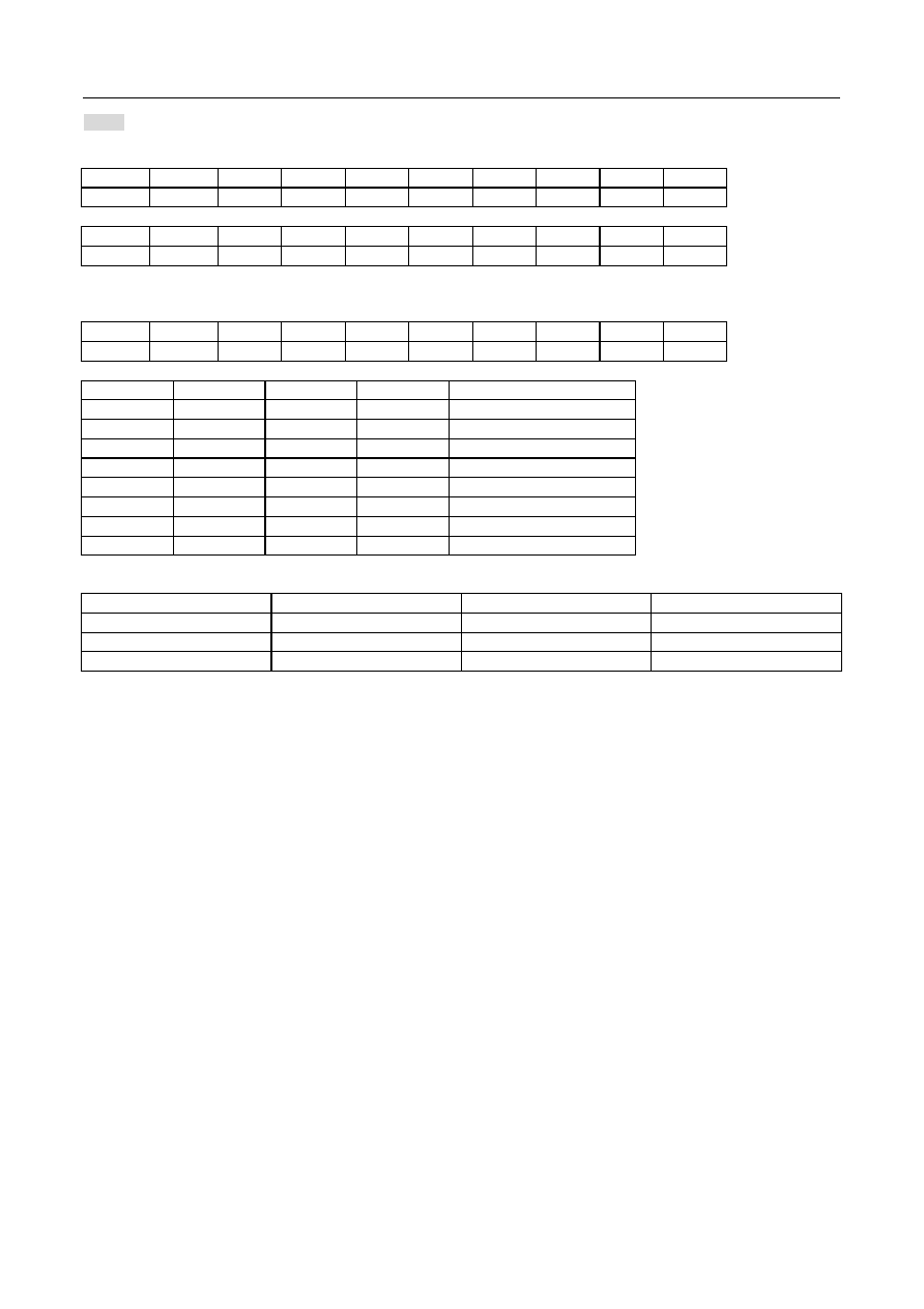
8. INSTRUCTION TABLE
COMMAND BYTE
INSTRUCTION A0
WR
(R/W)
D7 D6 D5 D4 D3 D2 D1 D0
DESCRIPTION
H=0 or 1
NOP
0
0 0 0 0 0 0 0 0 0
No
operation
Reset
0
0 0 0 0 0 0 0 1 1
Internal
reset
Function
set
0
0 0 0 1 0 0 PD V H
Power-down; entry mode;
Extended instruction control
Read status byte
0
1
PD
RST
BUSY
D
E
1
0
1
Read status byte
Read data
1
1
D
7
D
6
D
5
D
4
D
3
D
2
D
1
D
0
Read data from RAM
Write data
1
0
D
7
D
6
D
5
D
4
D
3
D
2
D
1
D
0
Write data to RAM
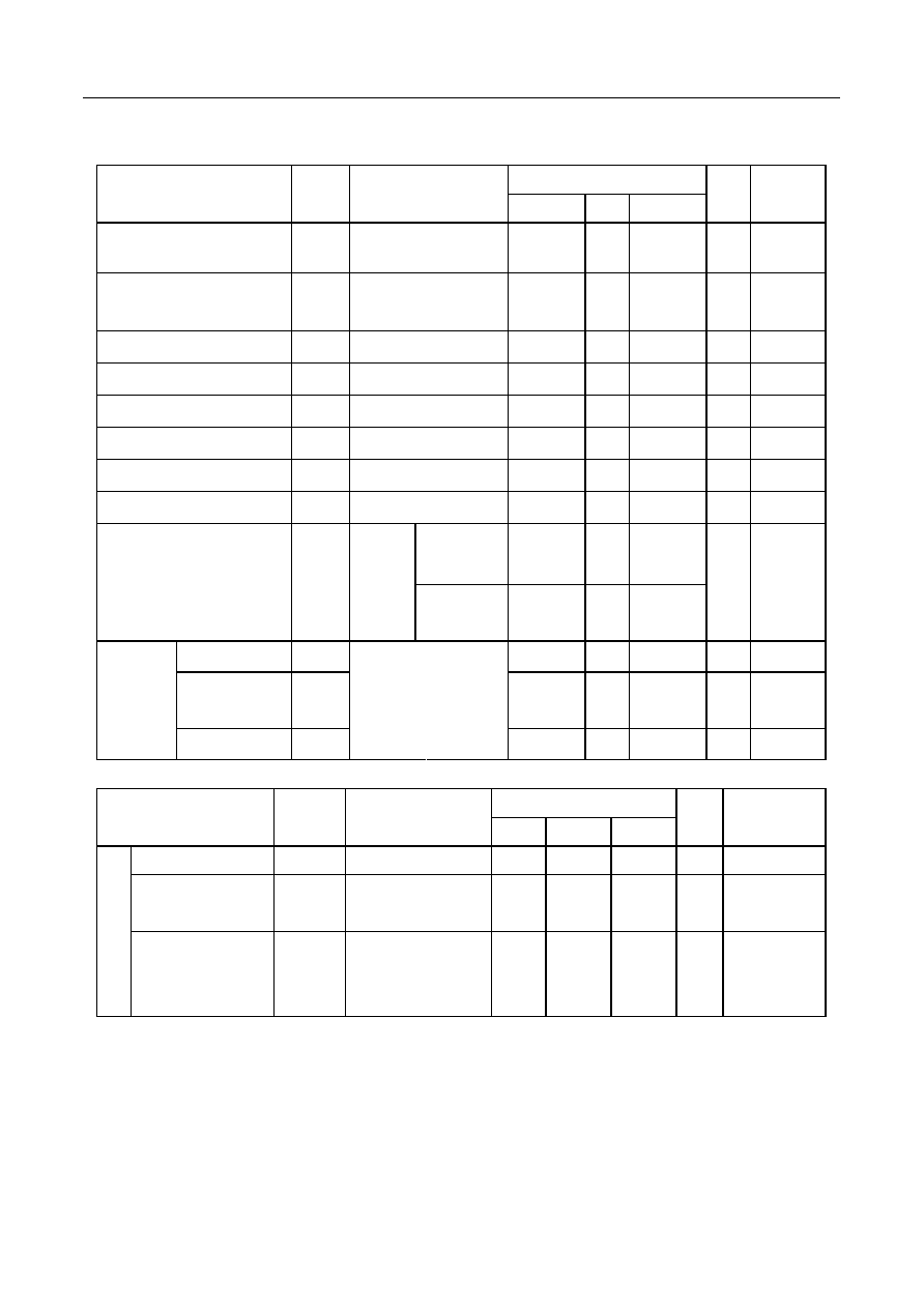
COMMAND BYTE
INSTRUCTION A0
WR
(R/W)
D7 D6 D5 D4 D3 D2 D1 D0
DESCRIPTION
H=0
Display control
0
0
0
0
0
0
1
D
0
E
Set display configuration
Set Y address of
RAM
0
0 0 1 0 0 Y
3
Y
2
Y
1
Y
0
Sets Y address of RAM
0Y9
Set X address of
RAM
0 0 1 X
6
X
5
X
4
X
3
X
2
X
1
X
0
Sets X address of RAM
0X101
H=1
S/W
Internal register
initial
0
0
0
0
0
0
0
0
0
0
0
1
1
0
1
0
1
1
0
0
S/W Internal register initial
Bias
system
0
0 0 0 0 1 0
BS
2
BS
1
BS
0
Sets bias system (BSx)
Reserved
0 0 0 1 X X X X X X
Do
not
use
Set V
OP
0
0
1
V
OP6
V
OP5
V
OP4
V
OP3
V
OP2
V
OP1
V
OP0
Write
V
OP
to register

ST7556
Ver 2.0
23/43 2003/11/27
9. INSTRUCTION DESCRIPTION
H="0" or "1"
Reset
This instruction resets initial display line, column address, page address, and common output status select to their initial
status. This instruction cannot initialize the LCD power supply, which is initialized by the RESB pin.
A0
WR(R/W)
D7 D6 D5 D4 D3 D2 D1 D0
0 0 0 0 0 0 0 0 1 1
Function Set
A0
WR(R/W)
D7 D6 D5 D4 D3 D2 D1 D0
0 0 0 0 1 0 0 PD V H
Flag Description
PD
All LCD outputs at VSS (display off), bias generator and VLCD generator off, VLCD can be
disconnected, oscillator off (external clock possible), RAM contents not cleared; RAM data
can be written.
PD=0:chip is active
PD=1:chip is in power down mode
V
When V = 0, the horizontal addressing is selected. The data is written into the DDRAM as
shown in Fig13.
When V = 1, the vertical addressing is selected. The data is written into the DDRAM as
shown in Fig12
H
When H = 0 the commands `display control', `set Y address' and `set X address'
can be performed, when H = 1 the others can be executed. The commands `write data'
and `function set' can be executed in both cases.
H=0:use basic instruction set
H=1:use extended instruction set
Read status byte
Indicates the internal status of the ST7556
A0
WR(R/W)
D7 D6 D5 D4 D3 D2 D1 D0
0 1
PD
RST
BUSY
D E 1 0 1
Flag Description
PD
PD=0:chip is active
PD=1:chip is in power down mode
RST
Indicates the initialization is in progress by RESET signal
0: chip is active,1:chip is being reset
BUSY
The device is busy when internal operation or reset. Any instruction is rejected until BUSY
goes LOW.
0:chip is active;1:chip is being busy
D E The bits D and E select the display mode.
0 0 Display
blank
0
1
All display segments on
1 0 Normal
mode
D,E
1 1 Inverse
video
mode
D2~D0 ST7556 will return the fix data "101" as identification bit
Write data
8-bit data of Display Data from the microprocessor can be written to the RAM location specified by the column address and
page address. The column address is increased by 1 automatically so that the microprocessor can continuously write data
to the addressed page. During auto-increment, the column address wraps to 0 after the last column is written.
A0
WR(R/W)
D7 D6 D5 D4 D3 D2 D1 D0
1 0
Write
data

ST7556
Ver 2.0
24/43 2003/11/27
H="0"
Display Control
This bits D and E selects the display mode.
A0
WR(R/W)
D7 D6 D5 D4 D3 D2 D1 D0
0 0 0 0 0 0 1 D 0 E
Flag Description
D E The bits D and E select the display mode.
0 0 Display
off
1 0 Normal
display
0
1
All display segments on
D,E
1 1 Inverse
video
mode
Set Y address of RAM
Y [3:0] defines the Y address vector address of the display RAM.
A0
WR(R/W)
D7 D6 D5 D4 D3 D2 D1 D0
0 0 0 1 0 0 Y
3
Y
2
Y
1
Y
0
X/Y Address range
Y
3
Y
2
Y
1
Y
0
CONTENT
ALLOWED
X-RANGE
0
0
0
0
Page0 (display RAM)
0 to 101
0
0
0
1
Page1 (display RAM)
0 to 101
0
0
1
0
Page2 (display RAM)
0 to 101
0
0
1
1
Page3 (display RAM)
0 to 101
0
1
0
0
Page4 (display RAM)
0 to 101
0
1
0
1
Page5 (display RAM)
0 to 101
0
1
1
0
Page6 (display RAM)
0 to 101
0
1
1
1
Page7 (display RAM)
0 to 101
1
0
0
0
Page8 (display RAM)
0 to 101
1
0
0
1
Page9 (display RAM)
0 to 101
Set X address of RAM
The X address points to the columns. The range of X is 0...101.
A0
WR(R/W)
D7 D6 D5 D4 D3 D2 D1 D0
0 0 1
X
6
X
5
X
4
X
3
X
2
X
1
X
0
X
6
X
5
X
4
X
3
X
2
X
1
X
0
Column
address
0 0 0 0 0 0 0
0
0 0 0 0 0 0 1
1
0 0 0 0 0 1 0
2
0 0 0 0 0 1 1
3
: : : : : : :
:
1 1 0 0 0 1 0
98
1 1 0 0 0 1 1
99
1 1 0 0 1 0 0
100
1 1 0 0 1 0 1
101
ST7556
Ver 2.0
25/43 2003/11/27
H="1"
S/W initial internal register
The 1
st
Instruction
A0
WR(R/W)
D7 D6 D5 D4 D3 D2 D1 D0
0 0 0 0 0 0 1 1 1 0
The 2
nd
Instruction
A0
WR(R/W)
D7 D6 D5 D4 D3 D2 D1 D0
0 0 0 0 0 1 0 0 1 0
System Bias
Select LCD bias ratio of the voltage required for driving the LCD.
A0
WR(R/W)
D7 D6 D5 D4 D3 D2 D1 D0
0 0 0 0 0 1 0
BS
2
BS
1
BS
0
BS
2
BS
1
BS
0
Bias Recommend
Duty
0 0 0 11
1:100
0 0 1 10
1:80
0 1 0 9
1:65/1:68
0 1 1 8
1:48
1 0 0 7
1/40:1/34
1 0 1 6
1/24
1 1 0 5
1:18/1:16
1 1 1 4 1:10/1:9/1:8
LCD bias voltage
Symbol
Bias voltage for 1/8 bias
Symbol
Bias voltage for 1/8 bias
VLCDIN VLCDIN V3
2/8
X
VLCDIN
V1
7/8 X VLCDIN
V4
1/8 X VLCDIN
V2
6/8 X VLCDIN
VSS
VSS

ST7556
Ver 2.0
26/43 2003/11/27
Set VOP value:
The operation voltage V
LCD
can be set by software.
V
0
=( a + V
OP
�
b ) (1)
Typical values for parameter for the HV-Generator programming
SYMBOL VALUE
UNIT
a 6.75
V
b 0.03
V
Caution
As the programming range for the internally generated VLCDIN allows values above the max allowed VLCDIN, the
customer has to ensure while setting the VOP register that under all condition and including all tolerances the
VLCD limit of max. 13V will never be exceeded. As VLCDIN increases with lower temperatures, care must be taken
not to set a Vop generating a VLCDIN voltage that will exceed the maximum of 10.6V when operating at �40 .
00
01
02
03
04
05
06
.....
7E
7D
7F
b
a
V
L2
VOP [6:0](programmed) {00 hex... 7F hex}
Fig 13. V
OP
programming of ST7556

ST7556
Ver 2.0
27/43 2003/11/27
10. COMMAND DESCRIPTION
Referential Instruction Setup Flow: Initializing with the built-in Power Supply Circuits
User System Setup by External Pins
Start of Initialization
Power ON(VDD-VSS) Keeping the /RES Pin="L"
Waiting for Stabilizing the Power
Release the reset state. (/RESB pin="H")
Waiting reset circuit stablized(>1ms)
End of Initialization
Function set PD=0 ,V=0 , H=1
SET Bias system
S/W Internal register initial (2-byte)
SET VOP
Function set PD=0 , V=0 , H=0
Display control D=1 E=0 (Normal)
Set X , Y address
Fig 14. Initializing with the Built-in Power Supply Circuits

ST7556
Ver 2.0
28/43 2003/11/27
Referential Instruction Setup Flow: Initializing without the built-in Power Supply Circuits
User System Setup by External Pins
Start of Initialization
Power ON(VDD-VSS) Keeping the /RES Pin="L"
Waiting for Stabilizing the Power
Release the reset state. (/RESB pin="H")
Waiting reset circuit stablized(>1ms)
Waiting for Stabilizing the LCD Power Levels
End of Initialization
Set Power Save
Function set PD=0 ,V=0 , H=1
SET Bias system
S/W Internal register initial
Function set PD=0 , V=0 , H=0
Display control D=1 E=0 (Normal)
Set X , Y address
Fig 15. Initializing without Built-in Power Supply Circuits

ST7556
Ver 2.0
29/43 2003/11/27
Referential Instruction Setup Flow: Data Displaying
End of Initialization
Display Data RAM Addressing by Instruction
[Set Page Address]
[Set Column Address]
Write Display Data by Instruction
[Display Data Write]
Turn Display ON/OFF Instruction
[Display ON/OFF]
End of Data Display
Figure 16.Data Displaying
Referential Instruction Setup Flow: Power OFF
Set Power Save by Instruction
Power OFF(VDD-VSS)
Optional Status
End of Power OFF
Figure 17. Power OFF

ST7556
Ver 2.0
30/43 2003/11/27
11. LIMITING VALUES
In accordance with the Absolute Maximum Rating System; see notes 1 and 2.
Parameter Symbol
Conditions
Unit
Power Supply Voltage
VDD1
�0.5 ~ +5.0
V
Power supply voltage
VSS2
1.7 ~ -3.3
V
Power supply voltage (VDD standard)
VLCDIN
�0.5 ~ +16
V
Power supply voltage (VDD standard)
V1, V2, V3, V4
0.3 to Vlcdin
V
Input voltage
VIN
�0.5 to VDD+0.5
V
Output voltage
VO
�0.5 to VDD+0.5
V
Operating temperature
TOPR
�40 to +85
�C
Storage temperature
TSTR
�65 to +150
�C
System (MPU) side
ST7556 chip side
V
LCD
V
SS
V
1
to V
4
V
SS
V
DD
V
SS
V
DD
Notes
1. Stresses above those listed under Limiting Values may cause permanent damage to the device.
2. Parameters are valid over operating temperature range unless otherwise specified. All voltages are with respect to
V
SS
unless otherwise noted.
3.
Insure that the voltage levels of V1, V2, V3, and V4 are always such that
Vout V0 V1 V2 V3 V4 Vss
ST7556
Ver 2.0
31/43 2003/11/27
12. DC CHARACTERISTICS
V
DD
= 1.7 V to 3.3V; V
SS
= 0 V; V
LCD
= 3.0 to 13.0V; T
amb
= -40 to +85; unless otherwise specified.
Rating
Item Symbol
Condition
Min. Typ.
Max.
Units
Applicable
Pin
Operating Voltage (1)
VDD1
1.7
--
3.3
V
Vss*1
Operating Voltage (2)
VDD2
(Relative to VSS)
1.7
--
3.3
V
VSS2
High-level Input Voltage
VIHC
0.7 x VDD --
VDD
V
*2
Low-level Input Voltage
VILC
VSS
--
0.3 x VDD V
*2
High-level Output Voltage
VOHC
0.7 x VDD --
VDD
V
*3
Low-level Output Voltage
VOLC
VSS
--
0.3 x VDD V
*3
Input leakage current
ILI
VIN = VDD or VSS
�1.0
--
1.0
A
*4
Output leakage current
ILO
VIN = VDD or VSS
�3.0
--
3.0
A
*5
VLCDIN =
13.0 V
-- 2.0
3.5
Liquid Crystal Driver ON
Resistance
RON
Ta =
25�C
(Relative
To VSS)
VLCDIN = 8.0
V
-- 3.2
5.4
K
SEGn
COMn *6
Internal Oscillator fOSC
--
80
84
kHz
*7
External
Input
fCL --
80
84
kHz
OSC
Oscillator
Frequency
Frame frequency fFRAME
1/65 duty Ta = 25�C
-- 77
80.3
Hz
Rating
Item Symbol
Condition
Min.
Typ. Max.
Units Applicable
Pin
Input voltage
VDD
(Relative To VSS)
1.7
--
3.3
V
Supply Step-up output
voltage Circuit
VLCDOUT (Relative To VSS)
--
--
13
V
VLCDOUT
Internal Power
Voltage regulator
Circuit Operating
Voltage
VLCDIN
(Relative To VSS)
--
--
13
V
VLCDIN

ST7556
Ver 2.0
32/43 2003/11/27
Dynamic Consumption Current : During Display, with the Internal Power Supply OFF Current consumed by total ICs when
an external power supply is used .
Rating
Test pattern
Symbol
Condition
Min.
Typ. Max.
Units Notes
Display Pattern
SNOW
ISS
VDD = 3.0 V,
V0 � VSS = 9.0 V
-- 300 400
A
*8
Power Down
ISS
Ta = 25�C
--
0.01
2
A
Notes to the DC characteristics
1. The maximum possible V
LCD
voltage that may be generated is dependent on voltage, temperature and (display) load.
2. Internal clock
3. Power-down mode. During power down all static currents are switched off.
4. If external V
LCDIN
, the display load current is not transmitted to I
DD
.
5. V
OUT
external voltage applied to VLCDIN pin; VLCDIN disconnected from VLCDOUT (no connect)
References for items market with *
*1 While a broad range of operating voltages is guaranteed, performance cannot be guaranteed if there are sudden
fluctuations to the voltage while the MPU is being accessed.
*2 The A0, D0 to D5, D6 (SI), D7 (SCL), /RD (E), /WR ,/(R/W), CSB, IMS, OSC, P/S, /DOF, RESB ,and MODE terminals.
*3 The D0 to D7, and OSC terminals.
*4 The A0,/RD (E), /WR ,/(R/W), CSB, IMS, OSC, P/S, /DOF, RESB ,and MODE terminals.
*5 Applies when the D0 to D5, D6 (SI), D7 (SCL) terminals are in a high impedance state.
*6 These are the resistance values for when a 0.1 V voltage is applied between the output terminal SEGn or COMn and the
various power supply terminals (V1, V2, V3, and V4). These are specified for the operating voltage range.
RON = 0.1 V /I (Where I is the current that flows when 0.1 V is applied while the power supply is ON.)
*7 The relationship between the oscillator frequency and the frame rate frequency.
*8,9It indicates the current consumed on ICs alone when the internal oscillator circuit and display are turned on.

ST7556
Ver 2.0
33/43 2003/11/27
13. TIMING CHARACTERISTICS
System Bus Read/Write Characteristics 1 (For the 8080 Series MPU)
t
AH8
t
AW8
t
CYC8
t
CCLR
,t
CCLW
t
CCHR
,t
CCHW
t
DS8
t
ACC8
t
OH8
t
DH8
/CS
WR,RD
A0
D0 to D7
(Write)
D0 to D7
(Read)
Figure 18.
(VDD = 3.3V , Ta =25�C)
Rating
Item
Signal Symbol
Condition
Min.
Max.
Units
Address hold time
tAH8
10
--
Address setup time
tAW8
0
--
System cycle time
A0
tCYC8 240
--
Enable L pulse width (WRITE)
tCCLW
80
--
Enable H pulse width (WRITE)
WR
tCCHW 80
--
Enable L pulse width (READ)
tCCLR
140
--
Enable H pulse width (READ)
RD
tCCHR 80
WRITE Data setup time
tDS8
40
--
WRITE Address hold time
tDH8
0
--
READ access time
tACC8
CL = 100 pF
--
70
READ Output disable time
D0 to D7
tOH8
CL = 100 pF
5
50
ns

ST7556
Ver 2.0
34/43 2003/11/27
(VDD = 2.7 V , Ta = 25�C )
Rating
Item Signal
Symbol
Condition
Min. Max.
Units
Address hold time
tAH8
15
--
Address setup time
tAW8
0
--
System cycle time
A0
tCYC8 400
--
Enable L pulse width (WRITE)
tCCLW
220
--
Enable H pulse width (WRITE)
WR
tCCHW 180
--
Enable L pulse width (READ)
tCCLR
220
--
Enable H pulse width (READ)
RD
tCCHR 180
--
WRITE Data setup time
tDS8
40
--
WRITE Address hold time
tDH8
0
--
READ access time
tACC8
CL = 100 pF
--
140
READ Output disable time
D0 to D7
tOH8
CL = 100 pF
10
100
ns
(VDD = 1.8V , Ta = 25�C )
Rating
Item Signal
Symbol
Condition
Min. Max.
Units
Address hold time
tAH8
30
--
Address setup time
tAW8
0
--
System cycle time
A0
tCYC8 640
--
Enable L pulse width (WRITE)
tCCLW
360
--
Enable H pulse width (WRITE)
WR
tCCHW 280
--
Enable L pulse width (READ)
tCCLR
360
--
Enable H pulse width (READ)
RD
tCCHR 280
WRITE Data setup time
tDS8
80
--
WRITE Address hold time
tDH8
30
--
READ access time
tACC8
CL = 100 pF
--
240
READ Output disable time
D0 to D7
tOH8
CL = 100 pF
10
200
ns
*1 The input signal rise time and fall time (tr, tf) is specified at 15 ns or less. When the system cycle time is extremely fast,
(tr +tf) (tCYC8 � tCCLW � tCCHW) for (tr + tf) (tCYC8 � tCCLR � tCCHR) are specified.
*2 All timing is specified using 20% and 80% of VDD as the reference.
*3 tCCLW and tCCLR are specified as the overlap between CSB being "L" and WR and RD being at the "L" level.

ST7556
Ver 2.0
35/43 2003/11/27
System Bus Read/Write Characteristics 1 (For the 6800 Series MPU)
t
AH6
t
AW6
t
CYC6
t
CCLR
,t
CCLW
t
CCHR
,t
CCHW
t
DS6
t
ACC6
t
OH6
t
DH6
CS1
(CS2="1")
E
A0
R/W
D0 to D7
(Write)
D0 to D7
(Read)
Figure 19.
(V
DD
= 3.3 V , Ta = 25�C )
Rating
Item Signal
Symbol
Condition
Min.
Max.
Units
Address hold time
tAH6
10
--
Address setup time
tAW6
0
--
System cycle time
A0
tCYC6 240
--
Enable L pulse width (WRITE)
tEWLW
80
--
Enable H pulse width (WRITE)
WR
tEWHW 80
--
Enable L pulse width (READ)
tEWLR
80
--
Enable H pulse width (READ)
RD
tEWHR 140
WRITE Data setup time
tDS6
40
--
WRITE Address hold time
tDH6
0
--
READ access time
tACC6
CL = 100 pF
--
70
READ Output disable time
D0 to D7
tOH6
CL = 100 pF
5
50
ns

ST7556
Ver 2.0
36/43 2003/11/27
(VDD = 2.7V , Ta =25�C )
Rating
Item
Signal Symbol
Condition
Min.
Max.
Units
Address hold time
tAH6
15
--
Address setup time
tAW6
0
--
System cycle time
A0
tCYC6 400
--
Enable L pulse width (WRITE)
tEWLW
220
--
Enable H pulse width (WRITE)
WR
tEWHW 180
--
Enable L pulse width (READ)
tEWLR
220
--
Enable H pulse width (READ)
RD
tEWHR 180
--
WRITE Data setup time
tDS6
40
--
WRITE Address hold time
tDH6
0
--
READ access time
tACC6
CL = 100 pF
--
140
READ Output disable time
D0 to D7
tOH6
CL = 100 pF
10
100
ns
(VDD =1.8V , Ta =25�C )
Rating
Item Signal
Symbol
Condition
Min. Max.
Units
Address hold time
tAH6
30
--
Address setup time
tAW6
0
--
System cycle time
A0
tCYC6
640
--
Enable L pulse width (WRITE)
tEWLW
360
--
Enable H pulse width (WRITE)
WR
tEWHW
280
--
Enable L pulse width (READ)
tEWLR
360
--
Enable H pulse width (READ)
RD
tEWHR
280
--
WRITE Data setup time
tDS6
80
--
WRITE Address hold time
tDH6
30
--
READ access time
tACC6
CL = 100 pF
--
240
READ Output disable time
D0 to D7
tOH6
CL = 100 pF
10
200
ns
*1 The input signal rise time and fall time (tr, tf) is specified at 15 ns or less. When the system cycle time is extremely fast,
(tr +tf) (tCYC6 � tEWLW � tEWHW) for (tr + tf) (tCYC6 � tEWLR � tEWHR) are specified.
*2 All timing is specified using 20% and 80% of VDD as the reference.
*3 tEWLW and tEWLR are specified as the overlap between CSB being "L" and E.

ST7556
Ver 2.0
37/43 2003/11/27
SERIAL INTERFACE (4-Line Interface)
t
CSH
/CS1
(CS2="1")
A0
SI
SCL
t
CCSS
t
SAS
t
SAH
t
SCYC
t
SLW
t
SHW
t
SDH
t
SDS
t
f
t
r
Fig 20.
(V
DD
=3.3V,Ta=25)
Rating
Item Signal
Symbol
Condition
Min. Max.
Units
Serial Clock Period
tSCYC
50
--
SCL "H" pulse width
tSHW
25
--
SCL "L" pulse width
SCL
tSLW
25
--
Address setup time
tSAS
20
--
Address hold time
A0
tSAH
10
--
Data setup time
tSDS
20
--
Data hold time
SI
tSDH
10
--
CS-SCL time
tCSS
20
--
CS-SCL time
CSB
tCSH
140
--
ns
(V
DD
=2.7V,Ta=25)
Rating
Item Signal
Symbol
Condition
Min.
Max.
Units
Serial Clock Period
tSCYC
100
--
SCL "H" pulse width
tSHW
50
--
SCL "L" pulse width
SCL
tSLW
50
--
Address setup time
tSAS
30
--
Address hold time
A0
tSAH
20
--
Data setup time
tSDS
30
--
Data hold time
SI
tSDH
20
--
CS-SCL time
tCSS
30
--
CS-SCL time
CSB
tCSH
160
--
ns

ST7556
Ver 2.0
38/43 2003/11/27
(V
DD
=1.8V,Ta=25)
Rating
Item Signal
Symbol
Condition
Min. Max.
Units
Serial Clock Period
tSCYC
200
--
SCL "H" pulse width
tSHW
80
--
SCL "L" pulse width
SCL
tSLW
80
--
Address setup time
tSAS
60
--
Address hold time
A0
tSAH
30
--
Data setup time
tSDS
60
--
Data hold time
SI
tSDH
30
--
CS-SCL time
tCSS
40
--
CS-SCL time
CSB
tCSH
200
--
ns
*1 The input signal rise and fall time (tr, tf) are specified at 15 ns or less.
*2 All timing is specified using 20% and 80% of VDD as the standard.

ST7556
Ver 2.0
39/43 2003/11/27
14. RESET TIMING
Internal
status
t
RW
t
R
During reset
Reset complete
/RES
Fig 21.
(VDD = 3.3V , Ta = �40 to 85�C )
Rating
Item Signal
Symbol
Condition
Min. Typ. Max.
Units
Reset time
tR
--
--
1
us
Reset "L" pulse width
RESB tRW
1
--
--
us
(VDD = 2.7V , Ta = �40 to 85�C )
Rating
Item Signal
Symbol
Condition
Min. Typ. Max.
Units
Reset time
tR
--
--
1.5
us
Reset "L" pulse width
RESB tRW
1.5
--
--
us
(VDD = 1.8V , Ta = �40 to 85�C )
Rating
Item Signal
Symbol
Condition
Min. Typ. Max.
Units
Reset time
tR
--
--
2.0
us
Reset "L" pulse width
RESB tRW
2.0
--
--
us

ST7556
Ver 2.0
40/43 2003/11/27
15. APPLICATION INFORMATION
The pinning of the ST7556 is optimized for single plane wiring e.g. for chip-on-glass display modules. Display size:
65x102 pixels.
Display 102X 65 pixels
ST7556
34
102
34
8
V
DD
V
SS
C
VDD
C
LVCD
V
DD2
V
DD1
V
SS
1
V
SS
2
V
LC
DOUT
V
LC
DIN
I/O
Fig 22. Application diagram: internal charge pump is used and single V
DD
V
DD2
C
VDD2
Display 102 X 65 pixels
ST7556
34
102
34
8
V
SS
C
LVCD
V
DD2
V
DD1
V
SS
1
V
SS
2
V
LC
DO
UT
V
LCDI
N
I/O
V
DD1
C
VDD1
Fig 23. Application diagram: Internal charge pump is used and two
separate V
DD1
(V
DD2
)

ST7556
Ver 2.0
41/43 2003/11/27
The required minimum value for the external capacitors in an application with the ST7556 are:
C
VLCD
= min. 100nF C
VDD1,2
= min. 1.0 F
Higher capacitor values are recommended for ripple reduction.
Display 102 X 65 pixels
ST7556
34
102
34
8
V
DD2
V
SS
C
VDD
V
DD2
V
DD1
V
SS
1
V
SS
2
V
LC
DOUT
V
LC
DI
N
I/O
V
L2
Fig 24. application diagram : External high voltage generation is used

ST7556
Ver 2.0
42/43 2003/11/27
16. THE MPU INTERFACE (REFERENCE EXAMPLES)
The ST7556 Series can be connected to either 80X86 Series MPUs or to 6800 Series MPUs. Moreover, using the serial
interface it is possible to operate the ST7556 series chips with fewer signal lines.
The display area can be enlarged by using multiple ST7556 Series chips. When this is done, the chip select signal can be
used to select the individual ICs to access.
(1) 8080 Series MPUs
A0
A1 to A7
IORQ
DO to D7
RD
WR
RES
V
CC
GND
MPU
A0
/CS
D0 to D7
E (/RD)
R/W (/WR)
/RES
V
DD
V
SS
ST75
56
Decoder
RESET
IMS
PS
V
DD
V
SS
(2) 6800 Series MPUs
A0
A1 to A7
IORQ
DO to D7
RD
WR
RES
V
CC
GND
MPU
A0
D0 to D7
/RD (E)
/WR (R/W)
/RES
V
DD
V
SS
ST75
56
/CS
Decoder
RESET
IMS
PS
V
DD
V
SS
(3) Using the Serial Interface (4-line interface)
A0
A1 to A7
Port 1
Port 2
RES
V
CC
GND
A0
/CS
SI
SCL
/RES
V
DD
V
SS
Decoder
RESET
IMS
PS
V
DD
V
SS
MP
U
S
T
75
56

ST7556
Ver 2.0
43/43 2003/11/27
17. ST7556 Application Note (96x65)
ST
7
5
5
6
V
L
C
D
O
U
T
V
L
C
D
I
N
V
S
S
V
S
S
2
V
4
...
V
0
M
Y
M
X
O
S
C
V
D
D
T
1
0
T
1
1
P
S
V
D
D
M
S
C
S
A
0
R
W
R
D
V
R
S
T
8
......
...
T
0
V
D
D
D
1
D
0
D
3
D
2
D
4
D
6
D
5
V
D
D
2
D
7
V
D
D
2
V
D
D
1
V
D
D
1
T
9
C
O
M
3
1
C
O
M
2
1
C
O
M
2
1
V
S
S
2
V
S
S
C
O
M
6
R
E
S
C
O
M
5
4
C
O
M
5
C
O
M
6
C
O
M
5
2
C
O
M
5
3
C
O
M
4
3
C
O
M
4
4
C
O
M
1
3
C
O
M
1
4
C
O
M
1
9
C
O
M
2
0
C
O
M
1
C
O
M
1
C
O
M
4
2
C
O
M
4
1
C
O
M
2
C
O
M
1
C
O
M
0
S
E
G
0
S
E
G
1
S
E
G
0
S
E
G
0
C
O
M
3
2
C
O
M
3
3
C
O
M
3
4
...
...
.........
.........
......
...
...
...
...
...
...
...
...
...
......
...
...
......
...
...
......
I
T
O
P
a
d
f
o
r
m
o
n
it
o
r
V
0
te
s
t
1
0
1
1
96
X
6
5
S
0
,
S
1
......
......
......
......
...
...
...
...
...
...
...
...
...
...
...
...
......
...
...
...
S
9
4
,
S
9
5
CO
M
3
1
.
.
CO
M
0
CO
M
6
4
.
.
CO
M
3
2
2
2
...
...
L
C
S
S
C
L
I
S
A
0
V
D
D
V
S
S
V
L
C
D
R
E
S
5
3
4
I
I S
C
S
V
D
D
TT