Skyworks Solutions, Inc. [978] 241-7000
∑
Fax [978] 241-7906
∑
Email sales@skyworksinc.com
∑
www.skyworksinc.com
1
Specifications subject to change without notice. 8/02A
GaAs IC SPDT Switch
Non-Reflective DC≠18 GHz
Features
Broadband, DC≠18 GHz
High Isolation, Low Loss, Fast Switching
100% On-Wafer RF and DC Testing
100% Visual Inspection to MIL-STD-883
MT 2010
AS018M2-00
Description
The AS018M2-00 GaAs SPDT matched MMIC FET
switch chip is ideal for applications requiring low loss, high
isolation and/or broadband operation. The GaAs MMIC
employs three shunt and two series FETs per arm for low
loss, high isolation switching together with a 50
load
which is switched into the high isolation arm for low return
loss. Power consumption is very low, typically 75
µ
A at
-5 V. While recommended for operation up to 18 GHz, the
switch performs well through 22 GHz.
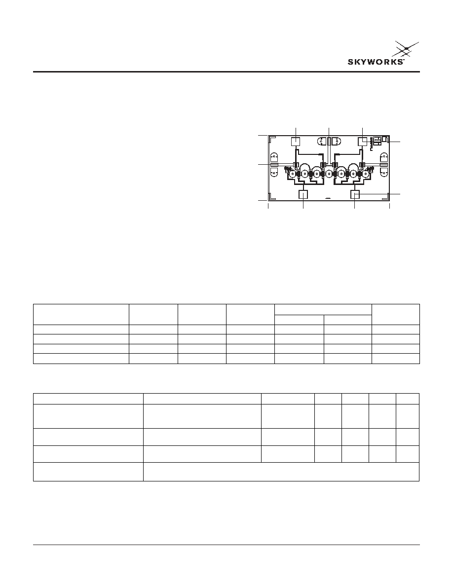
0.000
1.375
0.648
1.444
2.240
2.885
0.145
2.055
0.827
1.520
0.839
0.000
Chip Outline
Dimensions indicated in mm.
All DC (V) pads are 0.1 x 0.1 mm and RF In, Out pads are 0.07 mm wide.
Chip thickness = 0.1 mm.
2 GHz
10 GHz
18 GHz
2, 10 and 18 GHz
Parameter
1
Typ.
Typ.
Typ.
Min.
Max.
Unit
Insertion Loss
2
1.5 2.8
2.2
3.0
dB
Isolation 82
57
50
48
dB
Input Return Loss
17
8.5
12.5
7
dB
Output Return Loss
16
10.5
16
9
dB
Electrical Specifications at 25∞C
1. All measurements made in a 50
system, unless otherwise specified.
2. Insertion loss changes 0.003 dB/∞C.
3. Video feedthru measured with 1 ns risetime pulse and 500 MHz bandwidth.
Parameter
1
Condition
Frequency
Min.
Typ.
Max.
Unit
Switching Characteristics
Rise, Fall (10/90% or 90/10% RF)
1
µ
S
On, Off (50% CTL to 90/10% RF)
1
µ
S
Video Feedthru
3
20
mV
Input Power for 1 dB Compression
0/-5 V
0.5≠18 GHz
24
dBm
0.001 GHz
16
dBm
Intermodulation Intercept Point (IP3)
For Two-tone Input Power +13 dBm
0.5≠18 GHz
46
dBm
0.001 GHz
35
dBm
Control Voltages
V
Low
= 0 to -0.2 V @ 20 µA Max.
V
High
= -3 V to -6 V @ 250 µA Max.
Operating Characteristics at 25∞C
GaAs IC SPDT Switch Non-Reflective DC≠18 GHz
AS018M2-00
2
Skyworks Solutions, Inc. [978] 241-7000
∑
Fax [978] 241-7906
∑
Email sales@skyworksinc.com
∑
www.skyworksinc.com
Specifications subject to change without notice. 8/02A
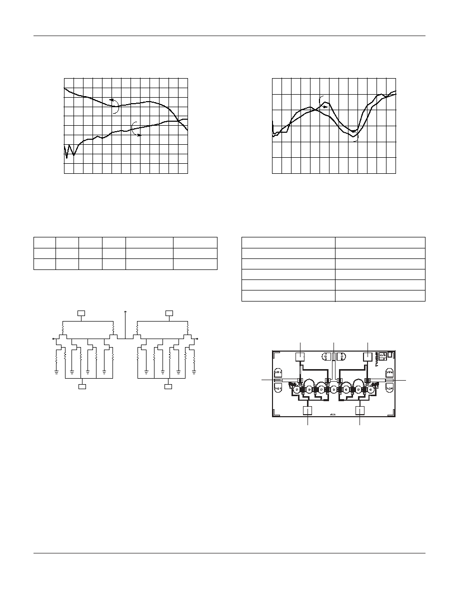
Insertion Loss and Isolation vs. Frequency
Frequency (GHz)
-9
-10
0
2
4
6
8 10 12 14 16 18 20 22 24 26
-8
-7
-6
-5
-4
-3
-2
-1
Inser
tion Loss (dB)
0
Isolation (dB)
-90
-100
-80
-70
-60
-50
-40
-30
-20
-10
0
Return Loss vs. Frequency
Frequency (GHz)
-25
-30
0
2
4
6
8 10 12 14 16 18 20 22 24 26
-20
-15
-10
-5
Input Retur
n Loss (dB)
Output Retur
n Loss (dB)
0
-25
-30
-20
-15
-10
-5
0
Typical Performance Data
Truth Table
V
1
V
2
V
3
V
4
J
1
≠J
2
J
1
≠J
3
0
-5
0
-5
Low Loss
Isolation
-5
0
-5
0
Isolation
Low Loss
V
1
J
1
V
4
V
3
V
2
J
3
J
2
Chip Layout
V
1
V
4
V
2
V
3
J
1
J
2
J
3
50
50
Circuit Schematic
Characteristic
Value
RF Input Power (RF In)
1 W
Control Voltage (V
C
)
+0.2 V, -7 V
Operating Temperature (T
OP
)
-55∞C to +125∞C
Storage Temperature (T
ST
)
-65∞C to +150∞C
Thermal Resistance (
JC
)
83∞C/W
Absolute Maximum Ratings