Skyworks Solutions, Inc. [781] 376-3000
∑ Fax [781] 376-3100 ∑ Email sales@skyworksinc.com ∑ www.skyworksinc.com
1
Specifications subject to change without notice. 2/03A
PHEMT GaAs IC High Power
Transfer Switch DC≠6 GHz
Applications
WLAN 802.11a, b, g Diversity
Features
Operating Frequency DC≠6 GHz
Positive Low Voltage Control
(0/+3 V Operation)
Low Insertion Loss
PHEMT Process
AS218-000
Description
The AS218-000 is a broadband transfer switch designed
to combine T/R and antenna diversity switching functions
on a single IC. The device is designed to handle high power
and maintain high linearity at low control voltages. This low
cost switch is ideal for Wi-Fi systems and is capable of
covering both the 2.4 and 5 GHz bands.
Parameter
1
Condition
Frequency
Min.
Typ.
Max.
Unit
Insertion Loss
2,4
Ant 1, Ant 2 to T
X
, R
X
0.10≠6.00 GHz
1.6
1.8
dB
2.40≠2.50 GHz
1.2
1.4
dB
5.15≠5.85 GHz
1.4
1.6
dB
Isolation
Ant 1, Ant 2 to T
X
, R
X
0.10≠6.00 GHz
17
19
dB
2.40≠2.50 GHz
32
37
dB
5.15≠5.85 GHz
17
19
dB
Return Loss
3
Ant 1, Ant 2 to T
X
, R
X
0.10≠6.00 GHz
10
dB
2.40≠2.50 GHz
15
dB
5.15≠5.85 GHz
20
dB
Electrical Specifications at 25∞C (0, +3 V)
Preliminary
Parameter
Condition
Frequency
Min.
Typ.
Max.
Unit
2nd and 3rd Harmonic
23 dBm Input @ 0,+3 V
2≠6 GHz
63
dBc
P
1 dB
2≠6 GHz
33
dBm
IIP3
20 dBm Per Tone
2≠3 GHz
54
dBm
22 dBm Per Tone
5≠6 GHz
47
dBm
Control Voltages
V
Low
= 0≠0.2 V @ 20
µA Max.
V
High
= 3≠5 V @ 200
µA Max.
Operating Characteristics at 25∞C (0, +3 V)
1. All measurements made in a 50
system.
2. Insertion loss changes by 0.003 dB/C.
3. Return loss for insertion loss state.
4. T
X
and R
X
paths can be used interchangeably.
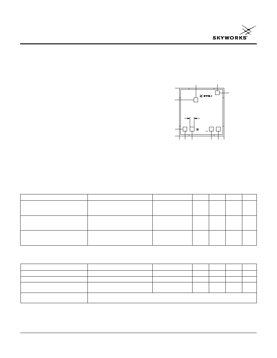
Outline Drawing
0.035
(0.90 mm)
0.027
(0.68 mm)
0.005
(0.13 mm)
0.000
0.004
(0.11 mm)
0.009
(0.24 mm)
0.024
(0.60 mm)
0.029
(0.73 mm)
0.033
(0.84 mm)
0.000
0.003
(0.08 mm)
SQ. TYP.
0.032
(0.81 mm)
0.028
(0.72 mm)
0.012
(0.31 mm)
Dimensions in inches (mm).
Chip thickness = 0.008 ± 0.001 (0.20 ± 0.025 mm).

PHEMT GaAs IC High Power Transfer Switch DC≠6 GHz
AS218-000
2
Skyworks Solutions, Inc. [781] 376-3000
∑ Fax [781] 376-3100 ∑ Email sales@skyworksinc.com ∑ www.skyworksinc.com
Specifications subject to change without notice. 2/03A
Pin Out (Top View)
R
X
V
1
ANT 1
ANT 2 V
2
T
X
"1" = +3 to +5 V.
"0" = 0 to +0.2 V.
Typical Performance Data (0, +3 V)
0
2
3
1
4
5
6
Insertion Loss (dB)
Frequency (GHz)
Insertion Loss vs. Frequency
-3.0
-2.8
-2.6
-2.4
-2.2
-2.0
-1.8
-1.6
-1.4
-1.2
-1.0
-0.8
-0.6
-0.4
-0.2
0
0
2
4
1
3
5
6
Isolation (dB)
Frequency (GHz)
Isolation vs. Frequency
-60
-55
-50
-45
-40
-35
-30
-25
-20
-15
-10
-5
0
Return Loss (dB)
Frequency (GHz)
Return Loss vs. Frequency
0
2
3
1
4
5
6
-50
-45
-40
-35
-30
-25
-20
-15
-10
-5
0
V
1
V
2
Insertion Loss Path
0
1
Ant 1 to T
X
, Ant 2 to R
X
1
0
Ant 2 to T
X
, Ant 1 to R
X
Truth Table
DC blocking caps required on RF lines for positive voltage operation.
Bond pad metalization: gold.
Backside metalization: none.
Bond pad dimensions: 0.003 (0.075 mm) x 0.003 (0.075 mm).
See application note, Handling GaAs MMIC Die.