Alpha Industries, Inc. [781] 935-5150
∑
Fax [617] 824-4579
∑
Email sales@alphaind.com
∑
www.alphaind.com
1
Specifications subject to change without notice. 10/98A
GaAs IC 4 Bit Digital Attenuator
2 dB LSB DC≠1 GHz
Features
s
2, 4, 8, 16 dB Bits
s
Designed for Cellular Radio Applications
s
Low Cost Plastic Package
s
For Extended Frequency Performance to
2 GHz Use the AD320-25
s
Low DC Power Consumption
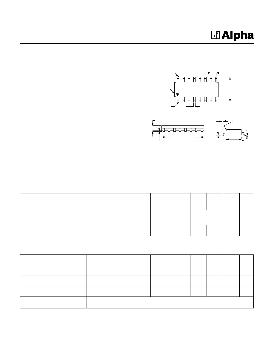
SOIC-16
AT001D4-25
Description
The AT001D4-25 is an IC FET digital attenuator consisting
of four monolithic attenuators with LSB of 2 dB and a total
attenuation of 30 dB with all attenuators connected.
The attenuator is packaged in the plastic 16 lead surface
mount package for low cost commercial cellular radio
applications.
Bias required is -5, 0 V. By "floating" the device, a bias of
+ 5 and 0 is required. Refer to the application note, "Switch
and Attenuator Mounting for Positive Voltage Operation,"
in the Application Notes section.
Electrical Specifications at 25∞C (0, -5 V)
Parameter
1
Frequency
2
Min.
Typ.
Max.
Unit
Insertion Loss
3
DC≠0.5 GHz
3.0
3.8
dB
DC≠1.0 GHz
3.7
4.0
dB
Attenuation Range
4
DC≠1.0 GHz
± 10% of Attenuation Setting
dB
in dB or ± 0.5 dB,
Whichever is Greater
VSWR (I/O)
DC≠0.5 GHz
1.45
1.8:1
DC≠1.0 GHz
1.5
1.8:1
0.158 (4.00 mm)
0.150 (3.80 mm)
0.068
(1.73 mm) MAX.
0.244 (6.20 mm)
0.228 (5.80 mm)
0.049 (1.24 mm)
0.016 (0.41 mm)
0.016 MAX.
(0.41 mm)
x 45∞
CHAMFER
0.020 (0.51 mm)
0.013 (0.33 mm)
0.050
(1.27 mm) BSC
PIN 16
PIN 1
PIN 1
INDICATOR
0.394 (10.00 mm)
0.386 (9.80 mm)
0.010 (0.25 mm)
0.004 (0.10 mm)
0.0098 (0.25 mm)
0.0075 (0.19 mm)
8∞ MAX.
Parameter
Condition
Frequency
Min.
Typ.
Max.
Unit
Switching Characteristics
5
Rise, Fall (10/90% or 90/10% RF)
10
ns
On, Off (50% CTL to 90/10% RF)
20
ns
Video Feedthru
20
mV
Input Power for 1 dB Compression
0.5≠1.0 GHz
+24
dBm
0.001 GHz
+14
dBm
Intermodulation Intercept Point (IP3)
For Two-tone Input Power +13 dBm
0.5≠1.0 GHz
+43
dBm
0.001 GHz
+32
dBm
Control Voltages
V
Low
= 0 to -0.2 V @ 20 µA Max.
V
High
= -5 @ 50 µA to -8 V @ 200 µA Max.
Operating Characteristics at 25∞C (0, -5 V)
1. All measurements made in a 50
system, unless otherwise specified.
2. DC = 300 kHz.
3. Insertion loss changes by 0.003 dB/∞C.
4. Attenuation referenced to insertion loss.
5. Video feedthru measured with 1 ns risetime pulse and 500 MHz bandwidth.
2
Alpha Industries, Inc. [781] 935-5150
∑
Fax [617] 824-4579
∑
Email sales@alphaind.com
∑
www.alphaind.com
Specifications subject to change without notice. 10/98A
GaAs IC 4 Bit Digital Attenuator 2 dB LSB DC≠1 GHz
AT001D4-25
2 dB
4 dB
8 dB
16 dB
J
1
≠J
2
V
1
V
2
V
3
V
4
V
5
V
6
V
7
V
8
Attenuation
-5
0
-5
0
0
-5
-5
0
Reference I.L.
0
-5
-5
0
0
-5
-5
0
2 dB
-5
0
0
-5
0
-5
-5
0
4 dB
-5
0
-5
0
-5
0
-5
0
8 dB
-5
0
-5
0
0
-5
0
-5
16 dB
0
-5
0
-5
-5
0
0
-5
30 dB Max.
Truth Table
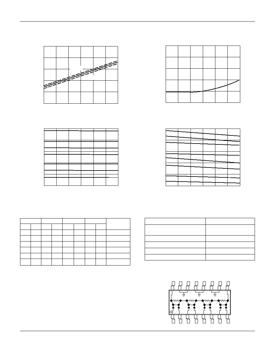
5
4
3
2
1
DC
0.4
0.8
1.2
Frequency (GHz)
Insertion Loss vs. Frequency
d
B
0
+85∞C
-40∞C
DC
0.4
0.8
1.2
Frequency (GHz)
d
B
2 Through 14 dB States vs. Frequency
15
12
9
6
3
0
DC
0.4
0.8
1.2
Frequency (GHz)
d
B
VSWR vs. Frequency (All States)
2.5
2.2
1.9
1.6
1.3
1.0
DC
0.4
0.8
1.2
Frequency (GHz)
d
B
16 Through 30 dB States vs. Frequency
30
27
24
21
18
15
Typical Performance Data (0, -5 V)
1
2
3
4
5
6
7
8
16
15
14
13
12
11
10
9
V
8
16 dB
8 dB
4 dB
2 dB
V
7
V
6
V
5
V
4
V
3
V
2
V
1
J
1
GND GND GND GND GND GND J
2
Characteristic
Value
RF Input Power
2 W > 500 MHz 0/-8 V
0.5 W @ 50 MHz 0/-8 V
Control Voltage
+0.2 V, -8 V
Operating Temperature
-40∞C to 85∞C
Storage Temperature
-65∞C to 150∞C
JC
25∞C/W
Absolute Maximum Ratings
Note: Exceeding these parameters may cause irreversible damage.
Pin Out