Data Sheet
101384B
© 2001, 2002 Skyworks Solutions, Inc., All Rights Reserved.
September 5, 2002
CX77129
System SmartTM PA Module for CDMA / AMPS (824≠849 MHz)
The CX77129 Power Amplifier Module is a dual-mode Code Division Multiple
Access (CDMA) / Advanced Mobile Phone Service (AMPS) module designed for
mobile units operating in the 824≠849 MHz cellular bandwidth. This device
meets stringent IS95 CDMA linearity requirements to and beyond 28 dBm output
power and can be driven to power output levels beyond 31 dBm for high
efficiency FM mode operation. The CX77129 System Smart
TM
design presents a
unique feature that enables exceptionally low average battery current
consumption with two control pins that accept digital signals provided by the
system's baseband ASIC. This digital control logic defines an RF power range of
operation for the PA. The decoding logic within the PA uses this information to
optimize efficiency within this power range while meeting the specification for
Adjacent Channel Power Ratio (ACPR).
The two control pins (referred to as V
CONT1
and V
CONT2
) allow the PA to be
switched into one of four states.
∑ State/Power-range 3--high power mode, linear up to P
OUT
= 28 dBm, total
PA current is typically 560 mA (V
CONT1
= High, V
CONT2
= High)
∑ State/Power-range 2--medium power mode, linear up to P
OUT
= 13 dBm,
total PA current is typically 130 mA (V
CONT1
= Low, V
CONT2
= High)
∑ State/Power-range 1--low power mode, linear up to P
OUT
= ≠5 dBm, total
PA current is typically 46 mA (V
CONT1
= Low, V
CONT2
= Low)
∑ State/Power-range 0--power-down mode, leakage current less than 5
µA
(V
CONT1
= Low, V
CONT2
= Low, V
REF
= 0.0 V)
The current in States 1 and 2 is much lower than that achieved in a conventional
Power Amplifier.
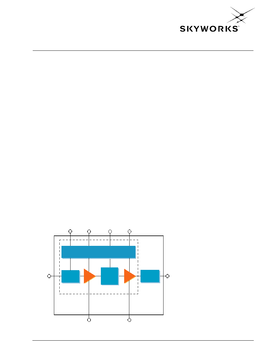
Functional Block Diagram
MMIC
MODULE
RFIN (2)
(6) RFOUT
V
CONT2
GND
GND2
V
CC
V
CONT1
Bias Circuits and Decoding Logic
Input
Match
DA
Inter
Stage
Match
PA
Output
Match
(7)
(4)
(8)
(1, 5)
(9)
V
REF
(3)
Distinguishing Features
∑
System Smart
TM
design
∑
Three switchable power states
∑
Dual digital input for setting
power states
∑
Power down control
∑
Higher efficiency over large
dynamic range
∑
8-pin LCC package
(6 x 6 x 1.5 mm)
Applications
∑
Digital cellular (CDMA)
∑
Analog cellular (AMPS)
∑
Wireless Local Loop (WLL)

Electrical Specifications
77129
System SmartTM PA Module for CDMA / AMPS (824≠849 MHz)
2
Skyworks Solutions, Inc. Proprietary
101384B
September 5, 2002
Electrical Specifications
The following tables list the electrical characteristics of the CX77129
System SmartTM
Power
Amplifier.
Table 1
lists the absolute maximum ratings while
Table 2
shows the recommended
operating conditions to achieve the performance characteristics listed in
Table 4
.
Table 3
presents a
truth table for the power ranges.
Table 1. Absolute Maximum Ratings
(1)
Parameter
Symbol
Minimum
Nominal
Maximum
Unit
Input Power
PR3 (High Power)
PR2 (Medium Power)
PR1 (Low Power)
P
IN
P
IN
P
IN
--
--
--
--
--
--
6.0
≠5.0
≠10.0
dBm
dBm
dBm
Supply Voltage
V
CC
--
3.4
6.0
Volts
Reference Voltage
V
REF
--
3.0
--
Volts
Case Operating Temperature
T
C
≠30
25
+110
∞C
Storage Temperature
T
TSTG
≠55
--
+125
∞C
NOTE(S):
(1)
No damage assumes only one parameter set at limit at a time with all other parameters set at or below
nominal value.
Table 2. Recommended Operating Conditions
Parameter
Symbol
Minimum
Nominal
Maximum
Unit
Supply Voltage
V
CC
3.2
3.4
4.2
Volts
Reference Voltage
V
REF
2.95
3.0
3.05
Volts
Operating Frequency
F
O
824.0
836.5
849.0
MHz
Operating Temperature T
O
≠30 +25 +85
∞C
Control Voltage (HIGH)
V
CONT1
, V
CONT2
2.0
--
4.2
Volts
Control Voltage (LOW)
V
CONT1
, V
CONT2
0.0
--
0.2
Volts
Table 3. Power Range Truth Table
Power Mode
V
REF
V
CONT1
(1)
V
CONT2
(1)
Range
PR3 (High Power)
3.0 V
HIGH
HIGH
13 dBm ~ 28 dBm
PR2 (Medium Power)
3.0 V
LOW
HIGH
≠5 dBm ~ 13 dBm
PR1 (Low Power)
3.0 V
LOW
LOW
≠5 dBm
Shut Down
0.0 V
LOW
LOW
--
NOTE(S):
(1)
High (2.0 V ~ 3.0 V) Low (0.0 V ~ 0.2 V).
2. To change between High Power and Medium Power mode, switch V
CONT
1 and V
CONT
2 accordingly. Please
reverse this procedure to power-down the module.

CX77129
Electrical Specifications
System SmartTM PA Module for CDMA / AMPS (824≠849 MHz)
101384B
Skyworks Solutions, Inc. Proprietary
3
September 5, 2002
Table 4. Electrical Specifications for CDMA/AMPS Nominal Conditions
(1)
Characteristic
Symbol
Condition
Minimum
Typical
Maximum
Unit
Output Power
Range 3
Range 2
Range 1
P
O
3
P
O
2
P
O
1
PR3 selected
PR2 selected
PR1 selected
--
--
--
--
--
--
28.0
13.0
≠5.0
dBm
dBm
dBm
Quiescent current
Iq1
PR1 selected
--
30.0
45.0
mA
Gain--Digital
PR3 selected
PR2 selected
PR1 selected
G
P
3
G
P
2
G
P
1
P
O
= 28.0 dBm
P
O
= 13.0 dBm
P
O
= ≠5.0 dBm
28.7
24.0
17.0
31.0
28.0
20.0
33.5
30.0
22.5
dB
dB
dB
Gain--Analog
Gp
P
O
= 31.0 dBm
29.0
31.0
33.5
dB
Total Supply Current
PR3 selected
PR2 selected
PR1 selected
I
CC
3
I
CC
2
I
CC
1
P
O
= 28.0 dBm
P
O
= 13.0 dBm
P
O
= ≠5.0 dBm
--
--
--
560.0
133.0
46.0
620
150
55
mA
mA
mA
Total Supply Current in
Power Down mode
I
PD
--
--
3.0
5.0
µA
Power-Added Efficiency
Digital
PR3 selected
PR2 selected
PAE3
PAE2
P
O
3 = 28.0 dBm
P
O
2 = 13.0 dBm
31.0
3.0
33.0
4.5
--
--
%
%
Power Added Efficiency
Analog
PAEa
P
O
= 31.0 dBm
40.0
45.0
--
%
Adjacent Channel
Power
(2)
885 kHz offset
1980 kHz offset
ACP
ACP
Any PR selected, up to
each range maximum
output power
--
--
≠49.0
≠61.5
≠47.0
(3)
≠58.5
dBc
dBc
Harmonic Suppression
Second
Third
2F
O
3F
O
Any PR selected, up to
each range maximum
output power
--
--
--
--
≠37.5
≠39.0
dBc
dBc
Noise Power in RX Band
RxBN
Any PR selected, up to
each range maximum
output power, 45 MHz
above Tx frequency
--
≠133.0
≠132.0
dBm/Hz
Noise Figure
NF
--
--
6.5
--
dB
Input Voltage Standing
Wave Ratio
PR3 selected
PR2 selected
PR1 selected
VSWR3
VSWR2
VSWR1
P
O
= 28.0 dBm
P
O
= 13.0 dBm
P
O
= ≠5.0 dBm
--
--
--
1.5:1
1.6:1
1.6:1
1.8:1
1.9:1
1.9:1
--
--
--
Stability (spurious
output)
--
5:1 VSWR all phases,
and any PR selected
--
--
≠60.0
dBc

Electrical Specifications
77129
System SmartTM PA Module for CDMA / AMPS (824≠849 MHz)
4
Skyworks Solutions, Inc. Proprietary
101384B
September 5, 2002
Switching speed between
states
-PR
From any PR to any
other PR
--
--
5.0
µsec
Ruggedness≠No damage
Ru
P
O
28 dBm
10:1
--
--
VSWR
NOTE(S):
(1)
V
CC
= 3.4 V, V
REF
= 3.0 V, Freq. = 836.5 MHz, T
C
= 25
∞C
(2)
ACP is specified per IS95 as the ratio of the total in-band power (1.23 MHz BW) to adjacent power in a 30 kHz BW
(3)
ACPR maximum for low power mode (PR1 selected) = 45.6 dBc.
Table 4. Electrical Specifications for CDMA/AMPS Nominal Conditions
(1)
Characteristic
Symbol
Condition
Minimum
Typical
Maximum
Unit

CX77129
Electrical Specifications
System SmartTM PA Module for CDMA / AMPS (824≠849 MHz)
101384B
Skyworks Solutions, Inc. Proprietary
5
September 5, 2002
Table 5. Electrical Specifications for CDMA/AMPS Recommended Operating Conditions
(1)
Characteristic
Symbol
Condition
Minimum
Maximum
Unit
Gain--Digital
PR3 selected
PR2 selected
PR1 selected
G
P
3
G
P
2
G
P
1
P
O
= 28.0 dBm
P
O
= 13.0 dBm
P
O
= ≠5.0 dBm
26.0
23.5
16.8
34.8
31.8
24.8
dB
dB
dB
Gain--Analog
Gp
P
O
= 31.0 dBm
26.0
35.8
dB
Power-Added Efficiency Digital
PR3 selected
PR2 selected
PAE3
PAE2
P
O
3 = 28.0 dBm
P
O
2 = 13.0 dBm
30.0
2.4
--
--
%
%
Power Added Efficiency Analog
PAEa
P
O
= 31.0 dBm
39.0
--
%
Adjacent Channel Power
(2)
885 kHz offset
1980 kHz offset
ACP
ACP
Any PR selected, up to
each range maximum
output power
--
--
≠44.0
≠57.0
dBc
dBc
Harmonic Suppression
Second
Third
2F
O
3F
O
Any PR selected, up to
each range maximum
output power
--
--
≠35.0
≠35.0
dBc
dBc
Input Voltage Standing Wave Ratio
PR3 selected
PR2 selected
PR1 selected
VSWR3
VSWR2
VSWR1
P
O
= 28.0 dBm
P
O
= 13.0 dBm
P
O
= ≠5.0 dBm
--
--
--
2.0:1
2.0:1
2.0:1
--
--
--
Switching speed between states
-PR
From any PR to any
other PR
--
5.0
µsec
NOTE(S):
(1)
Maximum overall conditions listed in Table 2.
(2)
ACP is specified per IS95 as the ratio of the total in-band power (1.23 MHz BW) to adjacent power in a 30 kHz BW