Data Sheet
101533A
© 2001, 2002, Skyworks Solutions, Inc., All Rights Reserved.
July 8, 2002
CX77131
System SmartTM PA Module for CDMA PCS (1850≠1910 MHz)
The CX77131 Power Amplifier Module (PAM) for Code Division Multiple Access
(CDMA) Personal Communications Service (PCS) incorporates a unique design
feature that enables exceptionally low average battery current consumption. The
CX77131 System Smart
TM
design incorporates two control pins that accept
digital signals provided by the system's baseband ASIC. This digital control logic
defines an RF power range of operation for the PA. The decoding logic within the
PA uses this information to optimize efficiency within this power range while
meeting the specification for Adjacent Channel Power Ratio (ACPR).
The two control pins (referred to as V
CONT1
and V
CONT2
) allow the PA be switched
into one of four states.
∑ State/Power-range 3--high power mode, linear up to P
OUT
= 28 dBm, total
PA current typically 550 mA (V
CONT1
= High, V
CONT2
= High)
∑ State/Power-range 2--medium power mode, linear up to P
OUT
= 13 dBm,
total PA typically 130 mA (V
CONT1
= Low, V
CONT2
= High)
∑ State/Power-range 1--low power mode, linear up to P
OUT
= ≠5 dBm, total
PA current less than 35 mA (V
CONT1
= Low, V
CONT2
= Low)
∑ State/Power-range 0--power-down mode, leakage current less than 5
µA
(V
CONT1
= Low, V
CONT2
= Low, V
REF
= 0.0 V)
The total PA currents in States 1 and 2 are much lower than those achieved in a
conventional Power Amplifier.
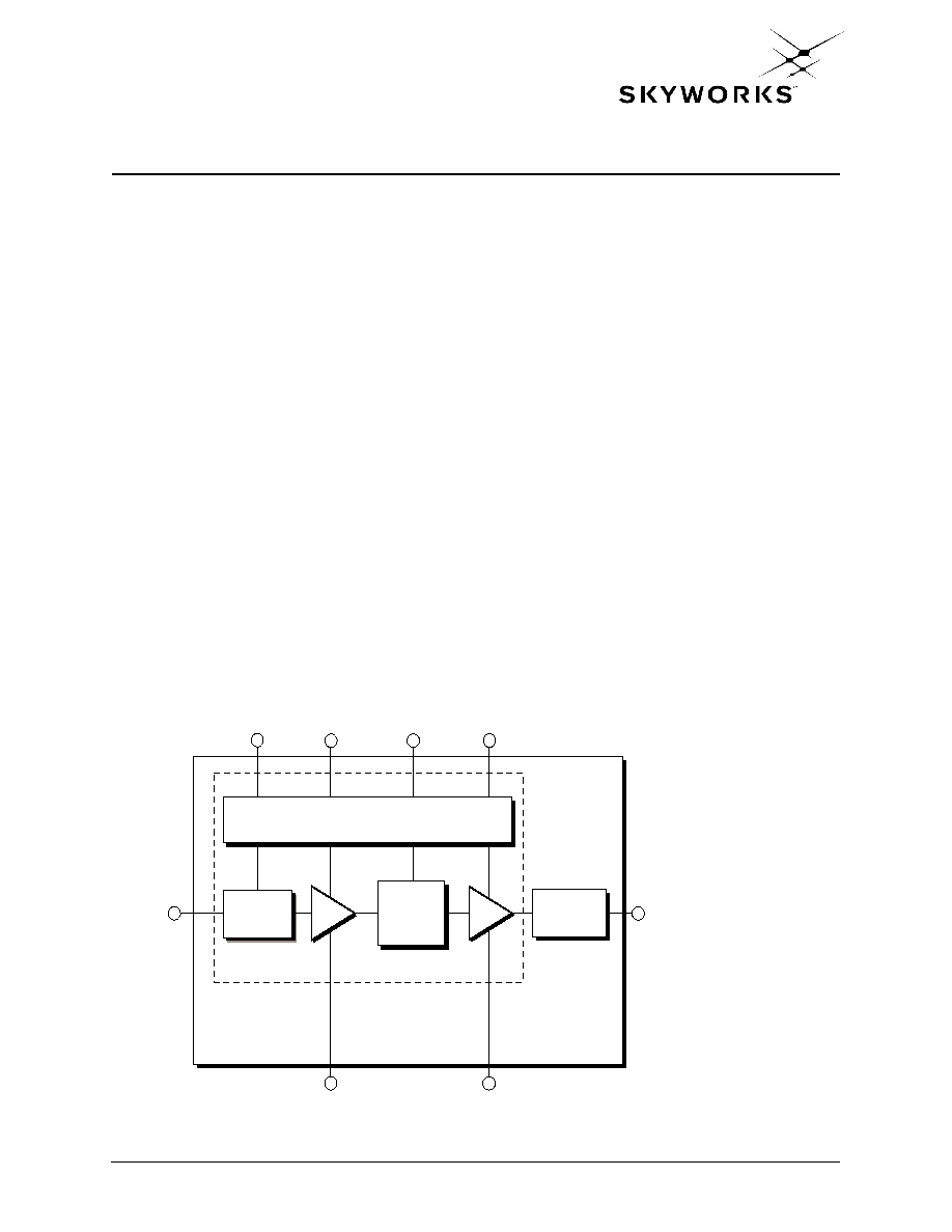
Functional Block Diagram
MMIC
MODULE
RF IN (2)
(6) RF OUT
VCONT2
VCC
VCONT1
Bias Circuits and Decoding Logic
Input
Match
DA
Inter
Stage
Match
PA
Output
Match
(7)
GND
(4)
(8)
(1, 5)
(9)
GND2
VREF
(3)
Distinguishing Features
∑
System Smart
TM
design
∑
Dual digital input for setting
power states
∑
Three switchable power states
∑
Power down control
∑
Higher efficiency over large
dynamic range
∑
8-pin LCC package
(6 x 6 x 1.5 mm)
∑
Full U.S. PCS coverage
Applications
∑
Personal Communications
Services (PCS)
∑
Wireless Local Loop (WLL)

2
Skyworks
101533A
July 8, 2002
Electrical Specifications
CX77131
System SmartTM PA Module for CDMA PCS (1850≠1910 MHz)
Electrical Specifications
The following tables list the electrical characteristics of the CX77131 System Smart
TM
Power
Amplifier.
Table 1
lists the absolute maximum ratings while
Table 2
shows the recommended
operating conditions to achieve the performance characteristics listed in
Table 4
.
Table 3
presents a truth table for the power ranges.
Table 1. Absolute Maximum Ratings
(1)
Parameter
Symbol
Minimum
Nominal
Maximum
Unit
RF Input Power
P
IN
--
--
7.0
dBm
Supply Voltage
V
CC
--
3.4
6.0
Volts
Reference Voltage
V
REF
--
3.0
--
Volts
Case Operating Temperature
T
C
≠30
+25
+110
∞C
Storage Temperature
T
STG
≠55
--
+125
∞C
NOTE(S):
(1)
No damage assuming only one parameter is set at limit at a time with all other parameters set at or below
nominal value.
Table 2. Recommended Operating Conditions
Parameter
Symbol
Minimum
Nominal
Maximum
Unit
Supply Voltage
V
CC
3.2
3.4
4.2
Volts
Reference Voltage
V
REF
2.95
3.0
3.05
Volts
Operating Frequency
F
O
1850
1880
1910
MHz
Operating Temperature
T
C
≠30
+25
+85
∞C
Control Voltage (HIGH)
V
CONT1
, V
CONT2
2.0
--
4.2
Volts
Control Voltage (LOW)
V
CONT1
, V
CONT2
0.0
--
0.2
Volts
Table 3. Power Range Truth Table
Power Mode
VREF
VCONT1
(1)
VCONT2
(1)
Range
PR3 (High Power)
3.0 V
HIGH
HIGH
13 dBm to 28 dBm
PR2 (Medium) Power)
3.0 V
LOW
HIGH
≠5 dBm to 13 dBm
PR1 (Low Power)
3.0 V
LOW
LOW
≠5 dBm
Shut Down
0.0 V
LOW
LOW
--
NOTE(S):
(1)
High (2.0 V ~ 3.0 V) low (0.0 V ~ 0.2 V).
(2)
To change between High Power and Medium Power mode, switch V
CONT1
and V
CONT2
accordingly. In order
to shut-down the module, turn off V
CONT1
/V
CONT2
and V
REF
accordingly (Refer to Table 3).

101533A
Skyworks
3
July 8, 2002
CX77131
Electrical Specifications
System SmartTM PA Module for CDMA PCS (1850≠1910 MHz)
Table 4. Electrical Specifications for CDMA PCS Nominal Operating Conditions
(1)
Characteristic
Condition
Symbol
Minimum
Typical
Maximum
Unit
Power-Range 3 Output Power
PR3
P
O
3
--
--
28.0
dBm
Power Range 2 Output Power
PR2
P
O
2
--
--
13.0
dBm
Power Range 1 Output Power
PR1
P
O
1
--
--
≠5.0
dBm
Quiescent current
PR1
Iq
--
27.0
35.0
mA
Gain
PR3 selected
PR2 selected
PR1 selected
P
O
= 28.0 dBm
P
O
= 13.0 dBm
P
O
= ≠5.0 dBm
G
P
3
G
P
2
G
P
1
25.0
20.5
12.3
26.2
23.0
15.0
28.0
25.0
19.5
dB
dB
dB
Total Supply Current
PR3 selected
PR2 selected
PR1 selected
P
O
= 28.0 dBm
P
O
= 13.0 dBm
P
O
= ≠5.0 dBm
I
CC
3
I
CC
2
I
CC
1
--
--
--
550.0
130.0
35.0
--
--
--
mA
mA
mA
Total Supply Current in Power-
Down mode
--
I
PD
--
3.0
5.0
µA
Power-Added Efficiency
PR3 selected
PR2 selected
P
O
3 = 28.0 dBm
P
O
2 = 13.0 dBm
PAE3
PAE2
30.0
4.0
32.0
4.5
--
--
%
%
Adjacent Channel Power
1.25 MHz offset
(2)
Any PR selected,
up to each range
maximum output
power
ACP
--
≠50.0
≠48.0
dBc
Harmonic Suppression
Second
Third
Any PR selected,
up to each range
maximum output
power
2F
O
3F
O
--
--
--
--
≠34.5
(3)
≠39.0
(3)
dBc
dBc
Noise Power in RX Band
Any PR selected,
up to each range
maximum output
power, 80 MHz
above TX frequency
RxBN
--
--
≠137.0
dBm/Hz
Noise Figure
--
NF
--
5.0
6.5
dB
Input Voltage Standing Wave Ratio
--
VSWR
--
1.8:1
2.0:1
--
Stability (spurious output)
5:1 VSWR all
phases, and any PR
selected
--
--
--
≠60.0
dBc
Switching speed between states
From any PR to any
other PR
-PR
--
5.0
20.0
µsec
NOTE(S):
(1)
V
CC
= 3.4 V, V
REF
= 3.0, Freq. = 1880 MHz, T
C
= 25
∞C
(2)
ACP is specified per IS95 as the ratio of the total power (1.23 MHz BW) to adjacent power in a 30 kHz BW
(3)
For Medium Mode, the maximum value is ≠30 dBc.

4
Skyworks
101533A
July 8, 2002
Electrical Specifications
CX77131
System SmartTM PA Module for CDMA PCS (1850≠1910 MHz)
Table 5. Electrical Specifications for CDMA PCS Recommended Operating Conditions
(1)
Characteristic
Condition
Symbol
Minimum
Maximum
Unit
Gain
PR3 selected
PR2 selected
PR1 selected
P
O
= 28.0 dBm
P
O
= 13.0 dBm
P
O
= ≠5.0 dBm
G
P
3
G
P
2
G
P
1
22.6
20.0
11.6
30.2
26.2
22.5
dB
dB
dB
Adjacent Channel Power
1.25 MHz offset
(2)
Any PR selected,
up to each range
maximum output
power
ACP
--
≠44.0
dBc
Harmonic Suppression
Second
Third
P
O
3 = 28.0 dBm
2F
O
3F
O
--
--
≠30.0
≠38.0
dBc
dBc
Noise Figure
--
NF
--
8.0
dB
Input Voltage Standing Wave Ratio
--
VSWR
--
2.3:1
--
NOTE(S):
(1)
Per Table 2, unless otherwise specified.
(2)
ACP is specified per IS95 as the ratio of the total power (1.23 MHz BW) to adjacent power in a 30 kHz BW

101533A
Skyworks
5
July 8, 2002
CX77131
Characterization Data
System SmartTM PA Module for CDMA PCS (1850≠1910 MHz)
Characterization Data
The following graphs illustrate the characteristics of a typical CX77131 System Smart
TM
Power
Amplifier under nominal operating conditions (V
CC
= 3.4 V, V
REF
= 3.0 V, room temperature,
1880 MHz) tested in an evaluation board described in the following section.
Figure 1. Total Battery Current vs. Output Power
0
100
200
300
400
500
600
700
-20
-15
-10
-5
0
5
10
15
20
25
30
P
O U T
(dBm)
Curre
nt
(m
A)
1850M
1880M
1910M
PR 2
PR 1
PR 3
Figure 2. Total Battery Current in Low to Medium Power Range
0
25
50
75
100
125
150
-20
-15
-10
-5
0
5
10
15
20
P
O U T
(dBm)
Curre
nt
(m
A)
1850M
1880M
1910M
PR 2
PR 1
PR 3