 | –≠–ª–µ–∫—Ç—Ä–æ–Ω–Ω—ã–π –∫–æ–º–ø–æ–Ω–µ–Ω—Ç: DD02-999 | –°–∫–∞—á–∞—Ç—å:  PDF PDF  ZIP ZIP |

Skyworks Solutions, Inc. ∑ Phone [781] 376-3000 ∑ Fax [781] 376-3100 ∑ sales@skyworksinc.com ∑ www.skyworksinc.com
200035 Rev. A ∑ Skyworks Proprietary Information ∑ Products and Product Information are Subject to Change Without Notice. ∑ October 4, 2004
1
DD02-999, DD02-999LF: Directional Detector
DATA SHEET
Features
Frequency coverage: 650 MHz to 3.0 GHz
Typical insertion loss < 0.2 dB to 2.3 GHz
Typical directivity > 23 dB
Small outline SC-88 (6 Lead SC-70)
Built-in temperature compensating diode
Low cost for high-volume handset applications
Available lead (Pb)-free MSL-2 @ 250 ∞C per JEDEC J-STD-020
Description
The DD02-999 directional detector is an alternative to the
DD01-999 with improved insertion loss and directivity with slightly
lower sensitivity. It is designed for handset power monitor applica-
tions from 800 MHz to 3 GHz. It is packaged in the small footprint,
SC-88 (6 lead SC-70) package. The DD02-999 incorporates a
directional coupler and two GaAs Schottky diodes on a monolithic
GaAs chip. By applying forward DC bias to both Schottky diodes,
the DD02-999 may be conveniently temperature compensated.
The DD02-999 is characterized from 500 MHz to 3 GHz and
generates a detected signal at 1.8 GHz of approximately 190 mV
at 10 mW input power. Each Schottky diode is forward biased to
approximately 5 µA.
12
3
65
4
RF Out
DC Bias/AC GND
Temp Comp Out
DD2
RF In
DC Bias/AC GND
Detected Out
Pin Out
Skyworks offers lead (Pb)-free "environmentally
friendly" packaging that is RoHS compliant
(European Parliament for the Restriction of
Hazardous Substances).
NEW

Skyworks Solutions, Inc. ∑ Phone [781] 376-3000 ∑ Fax [781] 376-3100 ∑ sales@skyworksinc.com ∑ www.skyworksinc.com
October 4, 2004 ∑ Skyworks Proprietary Information ∑ Products and Product Information are Subject to Change Without Notice. ∑ 200035 Rev. A
DATA SHEET ∑ DD02-999, DD02-999LF
2
Parameter
Frequency
Min.
Typ.
Max.
Unit
Detected output voltage @ 10 dBm
0.8≠1.2 GHz
60
80
105
mV
1.8≠2.0 GHz
130
160
190
mV
Insertion loss
0.8≠1.2 GHz
0.10
0.20
dB
1.8≠2.0 GHz
0.20
0.30
dB
Input return loss
0.8≠1.2 GHz
30
22
dB
1.8≠2.0 GHz
25
20
dB
Output return loss
0.8≠1.2 GHz
30
22
dB
1.8≠2.0 GHz
25
20
dB
Directivity
0.8≠1.2 GHz
17
20
dB
1.8≠2.0 GHz
16
13
dB
Schottky noise voltage (1 MHz bandwidth)
RF power off
200
µV
Schottky diode DC voltage
RF power off
510
mV
DC offset voltage
RF power off
-5
0
+5
mV
Video resistance
RF power off
7500
Electrical Specifications at 25 ∞C
Conditions: 10 dBm input power, 1 V applied to Pin 2 and 5 (See test circuit).
All data was taken with R
LOAD
= 100 k
.
Detected output voltage is the difference between V
REF
and V
DET
. A digital voltmeter was used
as a differential amplifier.

DATA SHEET ∑ DD02-999, DD02-999LF
Skyworks Solutions, Inc. ∑ Phone [781] 376-3000 ∑ Fax [781] 376-3100 ∑ sales@skyworksinc.com ∑ www.skyworksinc.com
200035 Rev. A ∑ Skyworks Proprietary Information ∑ Products and Product Information are Subject to Change Without Notice. ∑ October 4, 2004
3
Typical Performance Data
Insertion Loss vs. Frequency
Frequency (GHz)
Loss (dB)
-1.50
-1.25
-1.00
-0.75
-0.50
-0.25
0
0.5
1.0
1.5
2.0
2.5
3.0
Return Loss vs. Frequency
Frequency (GHz)
Return Loss (dB)
-50
-45
-40
-35
-30
-25
-20
-15
-10
-5
0
0.5
1.0
1.5
2.0
2.5
3.0
Input Return Loss
Output Return Loss
Differential Detected Voltage
vs. Frequency & Power
Frequency (GHz)
Detected Voltage (V)
0
0.5
1.0
1.5
2.0
2.5
3.0
3.5
4.0
4.5
5.0
0.5 0.7 0.9 1.1 1.3 1.5 1.7 1.9 2.1 2.3 2.5
+25 dBm
+30 dBm
+35 dBm
Differential Detected Voltage
vs. Frequency and Power
Frequency (GHz)
Detected Voltage (V)
0
0.2
0.4
0.6
0.8
1.0
1.2
0.5 0.7 0.9 1.1 1.3 1.5 1.7 1.9 2.1 2.3 2.5
5 dBm
10 dBm
15 dBm
20 dBm
Differential Detected Voltage vs.
Power and Temperature @ 900 MHz
Power (dBm)
Detected Voltage (V)
0
2
4
6
8
10
12
0
0.01
0.02
0.03
0.04
0.05
0.06
0.07
0.08
0.09
0.10
25 ∞C
85 ∞C
-40 ∞C
Differential Detected Voltage vs.
Power and Temperature @ 900 MHz
Power (dBm)
Detected Voltage (V)
0
0.5
1.0
1.5
2.0
2.5
3.0
0
3
6
9
12 15 18 21 24 27 30 33 36
25 ∞C
85 ∞C
-40 ∞C
Skyworks Solutions, Inc. ∑ Phone [781] 376-3000 ∑ Fax [781] 376-3100 ∑ sales@skyworksinc.com ∑ www.skyworksinc.com
October 4, 2004 ∑ Skyworks Proprietary Information ∑ Products and Product Information are Subject to Change Without Notice. ∑ 200035 Rev. A
DATA SHEET ∑ DD02-999, DD02-999LF
4
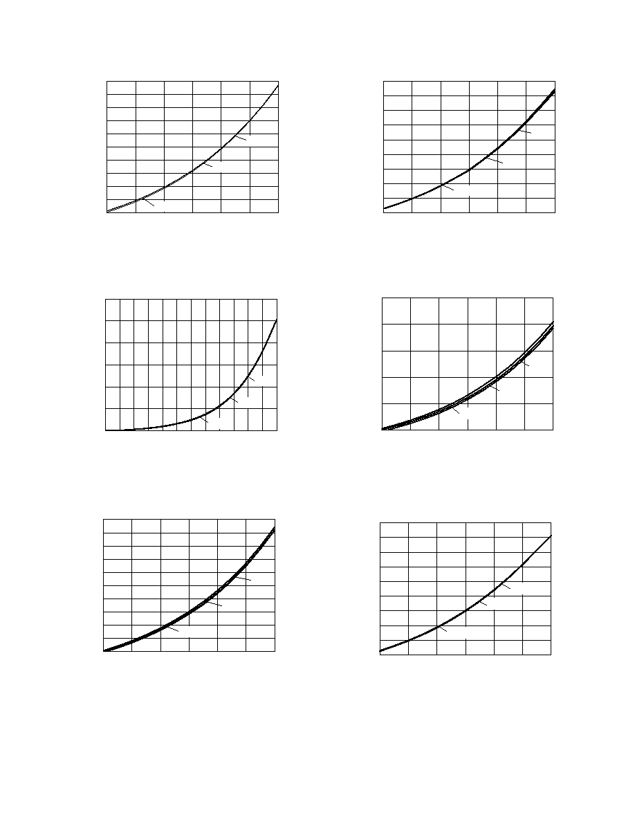
Differential Detected Voltage vs.
Power and Temperature @ 900 MHz
Power (dBm)
Detected Voltage (V)
0.09
0.14
0.19
0.24
0.29
0.34
0.39
0.44
0.49
0.54
0.59
12
14
16
18
20
22
24
25 ∞C
85 ∞C
-40 ∞C
Differential Detected Voltage vs.
Power and Temperature @ 900 MHz
Power (dBm)
Detected Voltage (V)
0.50
0.75
1.00
1.25
1.50
1.75
2.00
2.25
2.50
2.75
24
26
28
30
32
34
36
25 ∞C
85 ∞C
-40 ∞C
Differential Detected Voltage vs.
Power and Temperature @ 1900 MHz
Power (dBm)
Detected Voltage (V)
0
2
4
6
8
10
12
0
0.05
0.10
0.15
0.20
0.25
25 ∞C
85 ∞C
-40 ∞C
Differential Detected Voltage vs.
Power and Temperature @ 1900 MHz
Power (dBm)
Detected Voltage (V)
0
1.0
2.0
3.0
4.0
5.0
6.0
0
3
6
9
12 15 18 21 24 27 30 33 36
25 ∞C
85 ∞C
-40 ∞C
Differential Detected Voltage vs.
Power and Temperature @ 1900 MHz
Power (dBm)
Detected Voltage (V)
1.0
1.5
2.0
2.5
3.0
3.5
4.0
4.5
5.0
5.5
24
26
28
30
32
34
36
25 ∞C
85 ∞C
-40 ∞C
Differential Detected Voltage vs.
Power and Temperature @ 1900 MHz
Power (dBm)
Detected Voltage (V)
0.2
0.3
0.4
0.5
0.6
0.7
0.8
0.9
1.0
1.1
1.2
12
14
16
18
20
22
24
25 ∞C
85 ∞C
-40 ∞C

DATA SHEET ∑ DD02-999, DD02-999LF
Skyworks Solutions, Inc. ∑ Phone [781] 376-3000 ∑ Fax [781] 376-3100 ∑ sales@skyworksinc.com ∑ www.skyworksinc.com
200035 Rev. A ∑ Skyworks Proprietary Information ∑ Products and Product Information are Subject to Change Without Notice. ∑ October 4, 2004
5
220 pF
RF Out
22 nH
Bias In
V
REF
100 pF
1.8 k
1.8 k
100 pF
100 k
100 k
V
DET
RF In
SK39374
Rev 2
DD2
DD0*-92
Evaluation Board Layout
0.079 (2.00 mm)
± 0.008 (0.20 mm)
0.049 (1.25 mm)
± 0.004 (0.10 mm)
0.008 (0.20 mm)
± 0.004 (0.10 mm)
0.087 (2.20 mm)
± 0.008 (0.20 mm)
0.035 (0.90 mm)
± 0.004 (0.10 mm)
0.002 (0.005 mm)
± 0.002 (0.005 mm)
0.037 (0.95 mm)
± 0.006 (0.15 mm)
0.010 (0.25 mm)
± 0.006 (0.15 mm)
0.0055
(0.14 mm)
± 0.0015
(0.04 mm)
0.0256 (0.65 mm)
BSC
0.009 (0.23 mm)
Ref.
Pin 1 Indicator
SC-88 (6 Lead SC-70)
RF In
RF Out
6
5
4
3
2
1
100 pF
100 k
1.0 V
1.8 k
1.8 k
22 nH
1 V
Bias
100 pF
100 k
150 pF
+
≠
Differential
Amplifier
Detect Out
V
DET
V
REF
Test Circuit
Characteristic Value
Incident power (CW)
4 W @ < 1 GHz
@ SWR = 2.0 max.
2 W @ 1≠2.5 GHz
DC bias current
10 mA
Operating temperature
-40 to +85 ∞C
Storage temperature
-65 to +150 ∞C
ESD
+200 V
Absolute Maximum Ratings
Performance is guaranteed only under the conditions listed in the specifications table and is
not guaranteed under the full range(s) described by the Absolute Maximum specifications.
Exceeding any of the absolute maximum/minimum specifications may result in permanent
damage to the device and will void the warranty.
CAUTION: Although this device is designed to be as robust as
possible, Electrostatic Discharge (ESD) can damage
this device. This device must be protected at all times
from ESD. Static charges may easily produce poten-
tials of several kilovolts on the human body or
equipment, which can discharge without detection.
Industry-standard ESD precautions must be employed
at all times.

Skyworks Solutions, Inc. ∑ Phone [781] 376-3000 ∑ Fax [781] 376-3100 ∑ sales@skyworksinc.com ∑ www.skyworksinc.com
October 4, 2004 ∑ Skyworks Proprietary Information ∑ Products and Product Information are Subject to Change Without Notice. ∑ 200035 Rev. A
DATA SHEET ∑ DD02-999, DD02-999LF
6
Copyright © 2002, 2003, 2004 Skyworks Solutions, Inc. All Rights Reserved.
Information in this document is provided in connection with Skyworks Solutions, Inc. ("Skyworks") products. These materials are provided by Skyworks as a service to its customers and may be
used for informational purposes only by the customer. Skyworks assumes no responsibility for errors or omissions in these materials. Skyworks may make changes to its documentation, products,
specifications and product descriptions at any time, without notice. Skyworks makes no commitment to update the information and shall have no responsibility whatsoever for conflicts,
incompatibilities, or other difficulties arising from future changes to its documentation, products, specifications and product descriptions.
No license, express or implied, by estoppel or otherwise, to any intellectual property rights is granted by or under this document. Except as may be provided in Skyworks' Terms and Conditions of
Sale for such products, Skyworks assumes no liability whatsoever in association with its documentation, products, specifications and product descriptions.
THESE MATERIALS ARE PROVIDED "AS IS" WITHOUT WARRANTY OF ANY KIND, EITHER EXPRESS OR IMPLIED OR OTHERWISE, RELATING TO SALE AND/OR USE OF SKYWORKS PRODUCTS INCLUDING
WARRANTIES RELATING TO FITNESS FOR A PARTICULAR PURPOSE, MERCHANTABILITY, PERFORMANCE, QUALITY OR NON-INFRINGEMENT OF ANY PATENT, COPYRIGHT OR OTHER INTELLECTUAL
PROPERTY RIGHT. SKYWORKS FURTHER DOES NOT WARRANT THE ACCURACY OR COMPLETENESS OF THE INFORMATION, TEXT, GRAPHICS OR OTHER ITEMS CONTAINED WITHIN THESE MATERIALS.
SKYWORKS SHALL NOT BE LIABLE FOR ANY DAMAGES, INCLUDING SPECIAL, INDIRECT, INCIDENTAL, OR CONSEQUENTIAL DAMAGES, INCLUDING WITHOUT LIMITATION, LOST REVENUES OR LOST
PROFITS THAT MAY RESULT FROM THE USE OF THESE MATERIALS WHETHER OR NOT THE RECIPIENT OF MATERIALS HAS BEEN ADVISED OF THE POSSIBILITY OF SUCH DAMAGE.
Skyworks products are not intended for use in medical, lifesaving or life-sustaining applications. Skyworks' customers using or selling Skyworks products for use in such applications do so at their
own risk and agree to fully indemnify Skyworks for any damages resulting from such improper use or sale.
The following are trademarks of Skyworks Solutions, Inc.: SkyworksTM, the Skyworks logo, and Breakthrough SimplicityTM. Product names or services listed in this publication are for identification
purposes only, and may be trademarks of Skyworks or other third parties. Third-party brands and names are the property of their respective owners. Additional information, posted at
www.skyworkssolutions.com, is incorporated by reference.