
ControLink
TM
TM
86
Real-time Networking Software
For the COM20020 ARCNET Controller
Version 1.41
80 Arkay Dr.
Hauppauge, NY 11788
(516) 435-6000
Fax (516) 273-3123

ControLink
TM
TM
86 Realtime Networking Software
2
Disclaimer
Although the information contained in this document is believed to be accurate and reliable,
SMSC assumes no liability for inaccuracies or for changes to the information or to the
products. SMSC makes no representation, warranty or guarantee regarding the suitability
of any product for any particular purpose, assumes no liability which might arise out of use
of any product, and expressly disclaims any and all liability, including without limitation
consequential, incidental and special damages. SMSC products are not designed,
intended, authorized or warranted for use in any life support or other application where
product failure could cause or contribute to personal injury or severe property damage. Any
and all such uses without prior written approval of an Officer of SMSC and further testing
and /or modification will be fully at the risk of the customer. Neither the providing of this
information nor the sale of any product conveys, expressly or by implication, any license or
other right under any patent or other intellectual property of SMSC or others.
Trademarks
SMSC is a registered trademark and ControLink, ControLink86, ControLink51, are each
trademarks of Standard Microsystems Corporation. All other product and company names
listed are trademarks or trade names of their respective companies.

ControLink
TM
TM
86 Realtime Networking Software
3
TABLE OF CONTENTS
1 . O V E R V I E W . . . . . . . . . . . . . . . . . . . . . . . . . . . . . . . . . . . . . . . . . . . . . . . . . . . . . . . . . . . . . . . . . . . . . . . . . . . . . 5
1.1 AUDIENCE....... .......................................................................................................................... 5
1.2 DOCUMENT CONVENTIONS ..................................................................................................... 5
2 . I N T R O D U C T I O N A N D B A S I C A R C H I T E C T U R E . . . . . . . . . . . . . . . . . . . . . . . . . . . . . . . . 7
2.1 HOW TO USE CONTROLINK ..................................................................................................... 8
2.1.1 SOURCE CODE................................................................................................................. 9
2.1.2 DEMONSTRATION PROGRAMS. ................................................................................... 10
2.2 CONTROLINK SERVICES ........................................................................................................ 11
2.3 ADDRESSING MODES............................................................................................................. 11
2.4 SETTING UP CONTROLINK..................................................................................................... 13
2.4.1 SAP......... ........................................................................................................................ 13
2.4.2 INITIALIZING CONTROLINK ........................................................................................... 14
2.4.3 CLASS 1 DRIVER STATE MACHINE INITIALIZATION.................................................... 15
2.4.4 SAP ACTIVATION ........................................................................................................... 15
2.5 EXECUTING CONTROLINK ..................................................................................................... 16
2.5.1 CHECKING SAPS FOR INCOMING MESSAGES............................................................ 16
2.5.2 TRANSMITTING MESSAGES.......................................................................................... 17
2.5.3 AN EXAMPLE OF A COMPLETE PROGRAM:................................................................. 17
3 . L L C 1 - C L A S S 1 D R I V E R D E T A I L E D D E S C R I P T I O N . . . . . . . . . . . . . . . . . . . . . . 1 9
3.1 INTRODUCTION ....................................................................................................................... 19
3.2 OPERATE LOGICAL LINK CONTROL (IEEE 802.2) CLASS 1 SERVICES ............................... 19
3.3 LOGICAL LINK LAYER SOFTWARE STRUCTURE.................................................................. 19
3.4 LLC DATA STRUCTURES ........................................................................................................ 20
3.4.1 LLC_MSG DATA STRUCTURE (SAP) ............................................................................. 20
3.4.2 ADDITIONAL DATA STRUCTURES ................................................................................ 21
3.5 LLC1 FUNCTIONS .................................................................................................................... 21
3.5.1 llc1_request() ................................................................................................................... 21
3.5.2 llc_1service().................................................................................................................... 23
3.5.3 llc1_indication() ................................................................................................................ 23
3.5.4 llc1_group_indication() ..................................................................................................... 25
3.6 DESCRIPTION OF LLC1 SERVICES ........................................................................................ 26
3.6.1 STATION SERVICES....................................................................................................... 26
3.6.1.1 STATION INITIALIZATION................................................................................................ 26
3.6.1.2 STATION COMMAND/RESPONSE PROCESSING ........................................................ 27
3.6.1.3 DISABLE STATION/NODE................................................................................................ 27
3.6.1.4 STATION/NODE STATUS ................................................................................................ 27
3.6.2 SERVICE ACCESS POINT (SAP) SERVICES ................................................................. 28
3.6.2.1 SAP ACTIVATION/DEACTIVATION ................................................................................. 28
3.6.2.2 EXCHANGE ID (XID) REQUEST ...................................................................................... 28

ControLink
TM
TM
86 Realtime Networking Software
4
3.6.2.3 TEST REQUEST ............................................................................................................... 29
3.6.2.4 DATA REQUEST ............................................................................................................... 30
3.6.3 LLC PACKET FORMAT ................................................................................................... 31
4 . D 2 0 - H A R D W A R E ( L O W L E V E L ) D R I V E R D E T A I L E D D E S C R I P T I O N . 3 3
4.1 INTRODUCTION ....................................................................................................................... 33
4.2 DESCRIPTION OF STRUCTURE ............................................................................................. 34
4.3 EXPLANATION OF OPERATION.............................................................................................. 34
4.4 LOW LEVEL DRIVER FUNCTIONS SUMMARY ....................................................................... 35
4.5 CONFIGURABLE PARAMETERS ............................................................................................. 36
4.5.1 HARDWARE PARAMETERS ........................................................................................... 37
4.5.2 ARCNET PARAMETERS ................................................................................................. 37
4.5.3 PARAMETER LIST .......................................................................................................... 37
4.6 D20 DRIVER: DESCRIPTION OF THE FUNCTIONS ................................................................ 41
4.6.1 d20_set_defaults();........................................................................................................... 41
4.6.2 d20_get_parameter() ........................................................................................................ 42
4.6.3 d20_set_parameter() ........................................................................................................ 42
4.6.4 d20_init() . ........................................................................................................................ 43
4.6.5 d20_read_packet() ........................................................................................................... 44
4.6.6 d20_write_packet() ........................................................................................................... 45
4.6.7 d20_get_qentry() .............................................................................................................. 46
4.6.8 d20_network_map().......................................................................................................... 47
4.6.9 d20_registers() ................................................................................................................. 48
4.6.10 d20_diagnostic() ............................................................................................................. 49
4.6.11 d20_clear_diag()............................................................................................................. 50
4.6.12 d20_tokens() .................................................................................................................. 50
4.6.13 d20_exit() ....................................................................................................................... 50
4.6.14 d20_interrupt()................................................................................................................ 51
4.6.15 d20_check_int() .............................................................................................................. 51
4.6.16 d20_check_diag() ........................................................................................................... 53
4.6.17 read_data()..................................................................................................................... 53
4.6.18 write_data() .................................................................................................................... 54
4.6.19 check_network_status() .................................................................................................. 55
5 . L I S T O F E R R O R C O D E S R E T U R N E D . . . . . . . . . . . . . . . . . . . . . . . . . . . . . . . . . . . . . . . . . . 5 7
5.1 CODES RETURNED BY THE D20.C DRIVER FUNCTIONS ..................................................... 57
5.2 CODES RETURNED BY THE LLC1.C FUNCTIONS ................................................................. 57
6 . N E T W O R K S P E E D . . . . . . . . . . . . . . . . . . . . . . . . . . . . . . . . . . . . . . . . . . . . . . . . . . . . . . . . . . . . . . . . . . 5 8
7 . S A M P L E P R O G R A M A P P _ I N T . C . . . . . . . . . . . . . . . . . . . . . . . . . . . . . . . . . . . . . . . . . . . . . . . . 6 0
8 . G L O S S A R Y O F T E R M S . . . . . . . . . . . . . . . . . . . . . . . . . . . . . . . . . . . . . . . . . . . . . . . . . . . . . . . . . . . . 7 3

ControLink
TM
TM
86 Realtime Networking Software
5
1. OVERVIEW
ControLink is a library of software routines for building a real-time message passing network.
ControLink's architecture is based on a robust messaging service for encapsulating user-defined data
within the ARCNET
�
protocol. Thus existing higher level protocols or message delivery systems can be
executed on top of the ARCNET protocol. ControLink combines a flexible addressing scheme with a
robust set of network services to provide a simple and easy-to-use method of building a network.
ControLink offers the following to the user:
Transparent Interface - ControLink uses a networking concept called Service Access points or `SAPs' to
pass information between the upper layer software and the ControLink driver. SAPs are logical
addresses defined by the user to represent equipment codes, process variables (i.e. temperature,
pressure), or protocol codes. Each SAP is allocated a `mailbox' in system memory to store incoming
messages. A simple Indication routine notifies the host if any new messages are resident in that mailbox.
Standardization - ControLink forms the upper part of the Data Link Layer (Layer 2) of the OSI stack and
conforms to the IEEE 802.2 Link Layer Control specification. ARCNET conforms to ANSI 878.1.
Portability - ControLink 86 is written in ANSI C and compiled for the 80x86 processor family. Source
code and full documentation is included. Platform and compiler dependent code is unavoidable but is
kept to a minimum and kept in separate files that can be easily modified by the user.
1.1 AUDIENCE
ControLink is supplied to a programmer that wants to develop an ARCNET based application or system.
Therefore, a basic knowledge of the following topics is required to use ControLink effectively:
�
Programming in C
�
Local Area Network Layers concept
�
Data Link Layer purpose
Since ControLink is software written for SMSC's COM200xx it is implied that a programmer has the
knowledge of these network controllers as well as the architecture of the host systems on which
ControLink will be installed.
When beginning development the programmer is encouraged to obtain and study International standard
ISO 8802-2 (ANSI/IEEE Std. 802.2) document that describes the Data Link Layer concepts implemented
by ControLink.
1.2DOCUMENT CONVENTIONS
The following are the conventions used in this document:
Example
Description
ARCDEF.H
Uppercase letters indicate filenames, registers, and terms used at
the operating system command level.
USIGN8,int, d20_init()
Bold type indicates keywords, operators, language specific
characters, and library routines. Within discussions of syntax, bold
type indicates that the text must be entered exactly as shown.
expression
Words in italics indicate place holders for information a
programmer must supply.
[[option]]
Items in double square brackets are optional

ControLink
TM
TM
86 Realtime Networking Software
6
#include <dos.h>
Courier font is used for examples, user input, program output and
error messages in text.
while()
{
...
}
A column of or a row of three dots (ellipsis) indicates that a part of
an example code was intentionally omitted.
<ENTER>
Uppercase letters within the <> brackets denote the names of keys
on the keyboard.
"term"
Quotation marks indicate a new term introduced for the first time in
the text.
0x21
Represents hex number.
ControLink
TM
TM
86 Realtime Networking Software
7
2.INTRODUCTION AND BASIC ARCHITECTURE
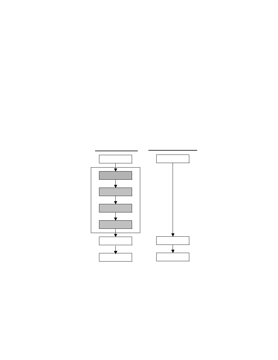
ControLink is designed to fit into a layered network architecture. The most commonly-used network
architecture is based on the OSI (Open System Interface) stack. The OSI layered architecture defines
only the interfaces and functionality between the seven layers of the OSI stack but does not describe a
particular protocol or implementation. The advantage of using such an architecture is that it can be easily
transported across many types of applications and provides for an easy to maintain and understandable
architecture. The full OSI implementation is a seven layer stack that calls for many functions that are not
pertinent to real-time or industrial applications. Many industrial networks such as ISA's proposed SP50
project, the Interoperable Systems Project (ISP), AHSRAE's BACNET, Siemens' PROFIBUS, and the
French FIP all use a streamlined version of the OSI stack that implements only three of the seven layers.
In the streamlined or collapsed OSI stack only layer 7 (the Application layer), layer 2 (Data link), and
layer 1 (Physical layer) are used (see Figure 1). ControLink is combined with SMSC's COM200xx family
of ARCNET Controllers for layers 1 and 2. The Application layer (layer 7) is inherently specific, as the
name suggests, to the application at hand. ControLink is intended to be a general purpose Data Link
level driver that can support a wide range of applications.
Full OSI Stack
Application
Presentation
Session
Transport
Network
Data Link
Physical
Not
Necessary
for
Realtime
Applications
Collapsed Stack
USER
Application
Data Link
Physical
CONTROLINK
COM20020
+
TRANSCEIVER
FIGURE 1 - NETWORK LAYERS CONCEPTS
ControLink is based around the IEEE 802.2 Data Link level specification. Conforming to the 802.2
specification presents a well-known and accepted data standard to many upper layer protocols such as
ASHRAE's BACNET and Novell's Netware. Also, ISA's SP50 and the ISP use many of same concepts
and procedures followed in the 802.2 specification. In addition to the basic 802.2 functionality,
ControLink contains many utilities that are commonly used including network mapping, initialization
functions, transferring the data between the physical network and logical addresses, compilation of
network statistics, and full error reporting.

ControLink
TM
TM
86 Realtime Networking Software
8
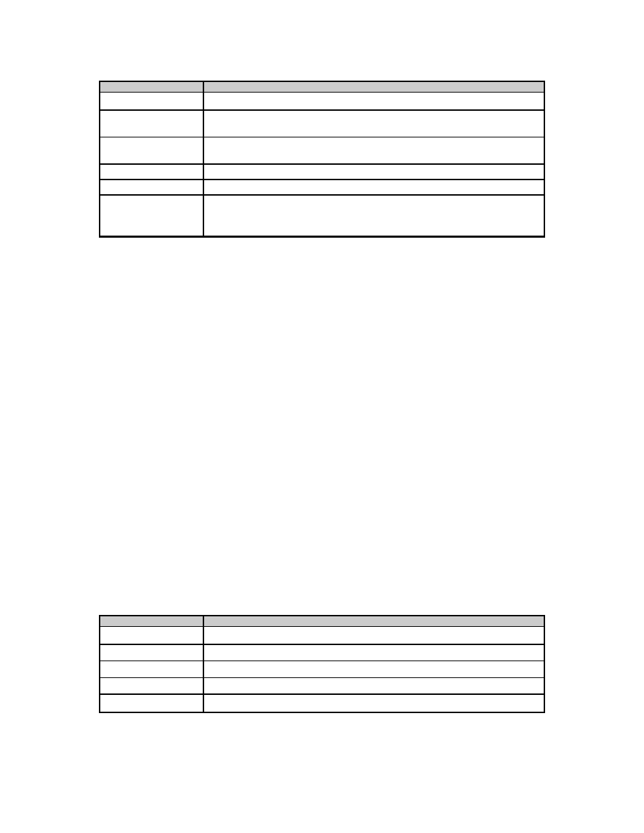
ControLink is composed of two parts, a host interface (referred to as the Class 1 Interface) and a low
level hardware interface. This architecture is illustrated by Figures 2 and 3. The host interface provides
the network interface to the host system. ControLink is based on a `mailbox' type messaging service
where the Class 1 driver acts as the `postal service'. The Class 1 driver uses a logical address called a
Service Access Point, or a SAP, to address each mailbox. The system designer assigns the `mailbox'
addresses at initialization using ControLink commands.
CONTROLINK
Basic
READ / WRITE
Routines
MAC Layer
Management
Network
Services
SAP & LLC
Management
D20.C
LLC1.C
FIGURE 2 - CONTROLINK ORGANIZATION
As messages are received by the hardware, ControLink queues each message for sorting and routing.
When used in its entirety, the architecture of the resulting control software is represented by Figure 3
Host System
LLC1 Class1 Driver
D20 Low Level Driver
COM20020
ARCNET Cable
FIGURE 3 - ARCHITECTURE OF THE CONTROL SOFTWARE BASED ON CONTROLINK
2.1HOW TO USE CONTROLINK
ControLink86 is delivered as source code to be linked with the target application. Aside from the source
code there are additional files that provide auxiliary functions like declarations and definitions.
Two programming examples complete with the application code, make files (for Microsoft Visual C++)
and executables are included. The distribution diskette structure has the following structure:

ControLink
TM
TM
86 Realtime Networking Software
9
0
CLINK1_4
2
INSTALL.BAT
2
README.TXT
0
APP_INT
0
APP_3
0
APP_5
0
APP_POLL
0
APP_3
0
APP_5
0
INCLUDE
0
SOURCE
2.1.1SOURCE CODE
The source code for ControLink86 resides in the following directories.
0
CLINK1_4
0
SOURCE
2
D20.C
2
LLC1.C
D20.C is a low level driver for the COM200xx ARCNET Local Area Network Controller that contains the
source code to accomplish the following tasks:
�
COM200xx control
�
interrupt control
�
configuration
�
transmit
�
receive
�
diagnostics
�
suspension
LLC1.C is an implementation of the Type 1 (connectionless) procedures for the Class 1 Logical Link
Control entities as described in the ANSI/IEEE 802.2
Standard. It contains the source code to accomplish the following tasks:
�
processing the incoming requests to the LLC layer
�
processing the data received by each SAP
�
issue indications to the upper layers as a result of incoming requests
�
scheduling transmission of SAP data via the MAC layer
ControLink 86 also contains header files that aid in the development process. These files contain basic
definitions related to the protocol and software structure, and are grouped in the subdirectory:
0
CLINK1_4
0
INCLUDE
2
ARCDEF.H
2
D20.H
2
LLC.H
2
LLC.H
2
MSC.H
2
T_*.H
ControLink
TM
TM
86 Realtime Networking Software
10
File
Description
ARCDEF.H
contains definitions related to the COM200xx LAN Controller
D20.H
contains definitions and declarations related to the low level driver
D20.C, error codes, and data structures
LLC.H
contains definitions related to the Logical Link Control driver error
codes and data structures
LLC1.H
contains the necessary declarations for the Class 1 LLC driver LLC1.C
MSC.H
contains compiler specific (Microsoft Visual C++) definitions
T_*.H
timing primitives to define a millisecond and a microsecond based on
the platform used for the host application. One of these files must be
included at the application level for the right timing primitives
2.1.2DEMONSTRATION PROGRAMS.
There are two demonstration programs packaged with the library code: APP_INT and APP_POLL. These
two programs show the operation of ControLink in the interrupt mode of the D20 driver and the polling
mode of the D20 driver.
Both demonstration programs were built using Microsoft Corporation Visual C++ C compiler and
development environment. The makefiles (*.mak) rely on the existence of the C:\MSVC development
environment. APP_INT demonstrates the use of D20 driver in the interrupt mode. This is an interactive
program that lets the user configure the D20 driver for various physical interface parameters, status
reporting and I/O interface.
0
CLINK1_4
0
APP_INT
2
APP_INT.C
0
APP_3
2
APP_INT.EXE
2
APP_INT.MAK
2
D20.PAR
2
PLATFORM.H
0
APP_5
2
APP_INT.EXE
2
APP_INT.MAK
2
D20.PAR
2
PLATFORM.H
.
These files have the following functions:
File
Description
APP_INT.C
source code for the demo.
APP_INT.EXE
executable demo for 80386 25MHz
APP_INT.MAK
makefile for the demo
D20.PAR
parameter list for the D20 driver
PLATFORM.H
description of the development environment
ControLink
TM
TM
86 Realtime Networking Software
11
APP_POLL is structured similarly to the APP_INT files
2.2CONTROLINK SERVICES
ControLink provides four services:
�
basic message transfer
�
remote node disconnect
�
link test
�
group of utilities
Service
Description
Basic Message
Transfer
used to transfer data to/from a node or group of nodes.
Node
Identification
asks the specified node `Are you out there?' or sends a `Here I am!'
message.
Link Test
a diagnostic service for verifying the integrity of a node and its host
CPU.
Utilities
Network Mapping, Network Statistics, Initialization functions
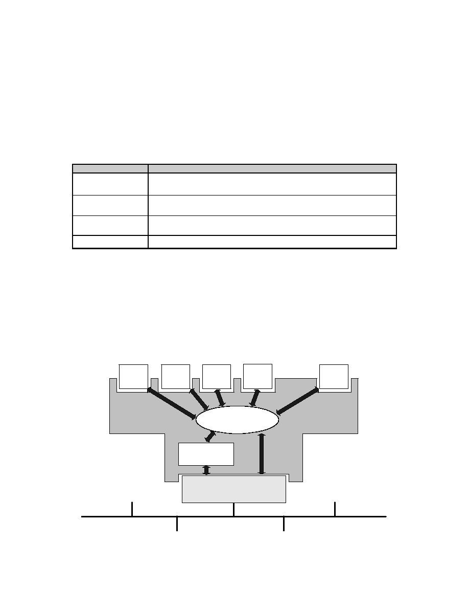
2.3ADDRESSING MODES
Addressing modes refer to addressing of the logical entities called SAPs (Service Access Points) created
and maintained by the ControLink software. The concept of SAPs is illustrated by the Figure 4.
ControLink implements the ANSI/IEEE 802.2 Standard that defines these addressing modes. A SAP is a
logical entity within one physical station. Other stations can send a packet to this physical station and this
packet will be redirected internally to the SAP for which it is intended.
Message
Queue
COM200xx
(Physical Network Address)
SAP1
SAP2
SAP3
SAP4
SAPn
ControLink86
Message Deliverer
Service Access Points: Logical Addresses For Data
Physical Medium
FIGURE 4 - SAP CONCEPT

ControLink
TM
TM
86 Realtime Networking Software
12
Thus ControLink offers four addressing modes:
�
individual
�
group
�
global
�
local.
Service
Description
Individual
destinations are single mailboxes (SAPs) only. Only one node can receive
the message.
Group
a single message can be received by more than one node. Membership is
established at each node. Identical group and individual addresses can
exist. For example, a SAP #1 can exist for group messages and a
separate SAP #1 can exist for the individual address.
Global
the message is received by all nodes on the network. SAP #255 is
reserved as the global address.
Local
is used to perform local function such as loopback and data link
initialization. SAP ID 0 is reserved for this purpose.
The Service Access Points can be used within the control system as the logical addresses. These logical
addresses can have different size of the buffer. Each of these logical addresses can hold the data for a
different aspect of the control process. This is illustrated by the Figure 5.
Physical Medium
Message
Queue
COM200xx
(Physical Network Address)
ControLink86
Message Deliverer
SAP1
SAP2
SAP3
SAP4
SAPn
fan
speed
temp.
sensor
power
control
status
APPLICATION
FIGURE 5 - USING SAPS

ControLink
TM
TM
86 Realtime Networking Software
13
2.4SETTING UP CONTROLINK
An ARCNET based application that wants to use ControLink must set up the necessary interface to
ControLink. This interface consists of SAP control structures (called LLC - MSG) and the buffers to hold
the data for each SAP. This interface is configured during the initialization phase of the application.
2.4.1 SAP
Each SAP in ControLink has an associated structure of the form:
struct LLC_MSG
{
USIGN8 event;
USIGN8 dstation;
USIGN8 ssap;
USIGN8 dsap;
USIGN8 group;
USIGN8 control;
USIGN8 msbcount;
USIGN8 lsbcount;
USIGN8 *msgptr;
};
Parameter
Description
event
specifies what kind of operation is to be performed on the SAP by the
ControLink
dstation
physical ARCNET address
ssap
source SAP number
dsap
destination SAP number
group
designation of individual or group SAP
0 - indicates an individual request
1 - indicates a group request
control
specifies the type request to the SAP
msbcount
lsbcount
the number of data bytes to be transmitted. Maximum is 504 bytes.
msgptr
array assigned to the SAP being referenced.
This structure is used to pass information to the Class 1 driver. Each service request to the Class 1 driver
must have the following elements of the structure assigned prior to the service request:
The remainder of the parameters are filled in by the Class 1 driver.
Every SAP used, with the exception of the local SAP (SAP 0) and the global SAP (SAP 0xff) requires a
global declaration assigning the SAP name to the type LLC_MSG. For example, the declaration for three
local SAPs and three group SAPs is as follows:
/* declare each ind. SAP as a structure of type LLC_MSG */
struct LLC_MSG SAP1, SAP2, SAP3;
/* declare group SAPs as a structure of type LLC_MSG */
struct LLC_MSG GSAP1, GSAP2, GSAP3;
/* reserve a storage area of 256 or 512 bytes for each declared SAP */
USIGN8 SAP1BUF[256];
USIGN8 SAP2BUF[256];
USIGN8 SAP3BUF[256];
USIGN8 GSAP1BUF[256];
USIGN8 GSAP2BUF[256];
USIGN8 GSAP3BUF[256];
void main(void)
{

ControLink
TM
TM
86 Realtime Networking Software
14
...
/* assign each SAP buffer to the structure */
SAP1.msgptr = SAP1BUF;
SAP2.msgptr = SAP2BUF;
SAP3.msgptr = SAP3BUF;
GSAP1.msgptr = GSAP1BUF;
GSAP2.msgptr = GSAP2BUF;
GSAP3.msgptr = GSAP3BUF;
}
Note: the size of the SAP buffer only has to be as large as the maximum message size. For example, if
a system has a maximum message size of 16 bytes then only a 16 byte buffer is necessary.
2.4.2 INITIALIZING CONTROLINK
The initialization of ControLink involves three simple processes:
�
hardware initialization
�
SAP activation
�
Class 1 driver state machine initialization
Initialization of ControLink will involve requesting network services from the Class 1 driver. All Class 1
driver service requests are accomplished by using the llc1_request() routine. The llc1_request() routine
is of the form:
Example:
status = llc1_request( ssap, dsap, request, SAP structure);
llc1_request() routine is described in detail in Section 3.5.1.
To establish default settings for the hardware the d20_set_defaults() routine must be run first before any
further initialization can be accomplished. d20_set_defaults() initializes a parameter list. Please refer to
the low level driver description for further details. Hardware parameters can be changed using the
d20_set_parameter() and d20_get_parameter() routines. After setting the desired parameters the
d20_init() routine should be run to program the specified parameters into the hardware and to test the
hardware for functionality.
An important process that occurs during initialization is the selection of the physical ARCNET ID value.
The ARCNET specification mandates that each node have a unique Node ID on the network. ControLink
offers three methods of selecting a unique Node ID value:
�
Automatic Node ID generation
�
Software set
�
Hardware port or switch set
Method
Description
automatic
An algorithm is employed to select the first available Node ID on the
network. The search is started with the Node ID = 1 and ends when there is
no other node on the physical segment with the same Node ID.
software set
The ARCNET ID is predetermined and programmed into system non-
volatile memory (EPROM, PROM, EEPROM, FLASH, etc.). The stored
value is then passed to the parameter list and programmed into hardware
hardware set
The ARCNET ID value can be read from a switch at a specified hardware
port address. The port address is supplied by the programmer in the
parameter list. This is quickest method of finding a unique ID value. Refer
to COM2002x Data Sheet and to the EVB-PC2002x for information
necessary to customize the initialization of the hardware.

ControLink
TM
TM
86 Realtime Networking Software
15
2.4.3 CLASS 1 DRIVER STATE MACHINE INITIALIZATION
The Class 1 driver utilizes a state machine for processing all requests. The requests to the state machine
llc1_request() are sent from the application as well as the network (other mode) itself. The state
machine must be initialized to a known state to function properly. The service request
ENABLE_WITHOUT_DUP_ADDR_CHECK is used to initialize the state machine. See the Class 1
Driver Detail Description on how to request services from ControLink.
Example:
/* use ssap and dsap of 0 for internal operations */
status = llc1_request(0,0,ENABLE_WITHOUT_DUP_ADDR_CHECK, &SAP0);
if (status == E_OK)
{
printf("Station is up\n");
}
else
{
printf("Station is down\n");
}
2.4.4 SAP ACTIVATION
Each SAP to be used must be internally activated within ControLink using the
SAP_ACTIVATION_REQUEST service request to enable the SAP. This process is necessary so that
ControLink can determine which incoming messages have valid addresses and which ones do not.
Example:
/* enable SAP1, use 0 dsap because it is a local operation */
status = llc1_request(1,0, SAP_ACTIVATION_REQUEST, &SAP1);
/*
enable group SAP1, use 0 dsap because it is a local operation
set group member of structure SAP1 to 1 to indicate a group SAP
*/
GSAP1.group = 1;
status = llc1_request(1,0, SAP_ACTIVATION_REQUEST, &GSAP1);
To summarize, the entire initialization process is as follows:
void main(void)
{
USIGN8 status;
...
/* insert SAP buffer declaration as shown above */
...
/d20_set_defaults(); * set default parameters */
...
/* insert custom parameters here */
d20_set_parameter(d20_node_mode,1); /* select soft id selection */
...
status = d20_init();
if (status == E_OK)
{
printf("Network hardware is up and running\n");
}
else
{
printf("Error in hardware initialization\n");
}

ControLink
TM
TM
86 Realtime Networking Software
16
...
/* initialize Class 1 state machine with local SAP */
status = llc1_request(0,0,ENABLE_WITHOUT_DUP_ADDR_CHECK, &SAP0);
if (status == E_OK)
{
status = llc1_request(1,0, SAP_ACTIVATION_REQUEST, &SAP1);
if (status == E_OK)
{
printf("SAP 1 is up\n");
}
else
{
printf("Error in activating SAP 1\n");
}
GSAP1.group = 1;
status = llc1_request(1,0, SAP_ACTIVATION_REQUEST, &GSAP1);
if (status == E_OK)
{
printf("GSAP 1 is up\n");
}
else
{
printf("Error in activating GSAP 1\n");
}
}
...
} /* end main */
2.5EXECUTING CONTROLINK
Running ControLink is simple. Real-time systems often operate using a rotating scheduler calling several
routines at defined intervals. ControLink is designed to operate in such an environment. The Class 1
driver contains a routine called llc1_service(). llc1_service() is the key to proper and timely operation of
the network. As packets arrive at the node, the hardware interrupts the system. ControLink's low level
driver contains an interrupt handler that buffers the packet onto a queue maintained in system memory
and enables reception of another packet. Messages remain queued until the host system calls
llc1_service(). At this time, llc1_service reads the first packet from the top of the queue. llc1_service()
decodes the header information from the packet and makes a decision based on this information. The
following occurs for different services:
�
Node Identification - reception of this command causes an automatic response message from the
Class 1 state machine and buffers the message into the SAP specified in the dsap field of the
packet. This service is used to identify what class of LLC services is supported by the tested
station. See section 3.6.2.2.)
�
Link Test - reception of this command causes an automatic response message from the Class 1
state machine and buffers the message into the SAP specified in the dsap of the packet. The
reply is scheduled as early as possible. This is used to test the connection between the stations.
(See section 3.6.2.3.)
�
Basic Message Transfer - message is placed in the SAP buffer corresponding to the dsap address
found in the packet header and sets an indication flag to the host. (See section 3.6.2.4.)
Incoming messages will not be processed without calling llc1_service() first.
2.5.1CHECKING SAPS FOR INCOMING MESSAGES
ControLink provides a convenient method of checking each SAP buffer for new messages. The
llc1_indication() routine is used for checking the SAP for new messages. For group addresses use the
llc1_group_indication() routine.
Example: (check SAP 4 for messages)

ControLink
TM
TM
86 Realtime Networking Software
17
/* provide the indication routine with the sap # */
status = llc1_indication(4);
/* process returned status */
switch (status)
{
/* nothing was received */
case NO_INDICATION:
break;
/* basic message was received */
case UNITDATA_INDICATION:
/* insert processing direction here */
break;
/* Node Identification response was received */
case XID_INDICATION:
/* insert processing here */
break;
/* TEST Response frame received */
case TEST_INDICATION:
/* insert processing here */
break;
default:
break;
}
2.5.2 TRANSMITTING MESSAGES
Messages are sent using the llc1_request() routine as mentioned previously. For each message the
dstation
member of the associated source SAP data structure must be filled.
The Basic Data Transfer and Test Link service require data input from the user. In these cases, the data
length field (
msbcount
and
lsbcount
) must be filled and the SAP buffer from which the message is
originating must be filled with the actual message.
Example: (SAP 1 has an associated buffer SAPBUF_1 for the data)
/* transmit a basic data message of 1,2,3 */
/* transmit from SAP 1 of station 0xff to SAP 2 of station 0xfe */
sap1.dstation = 0xfe;/* fill in ARCNET destination ID */
sap1.msbcount = 0;/* only 3 bytes of data */
sap1.lsbcount = 3;
sap1.group = 0; /* fill with a 1 for group messages */
SAPBUF_1[i]=i+1;/*0 for individual recipient */
for(i = 0; I < 3; i++)
{
}
status = llc1_request(1,2,UNITDATA_REQUEST, &SAP1);
/* status return indicates successful reception or not */
2.5.3AN EXAMPLE OF A COMPLETE PROGRAM:
The following is a skeleton application that illustrates the usage of the ControLink86 functions.
/* include files */
...
/* application specific definitions */
...
/* global declarations: SAP structures, SAPBUF buffers, flags, etc */
struct LLC_MSG SAP[MAX_SAPS];
USIGN8 SAPBUF[MAX_SAPS][MAX_SAPBUF];
...
/* application function prototypes */

ControLink
TM
TM
86 Realtime Networking Software
18
...
void main(void)
{
/* initialize network hardware - COM2002x */
/* initialize ControLink */
/* initialize SAPs */
/* control loop */
while(1)
{
/* packet received from the network */
if(NETWORK EVENT)
{
llc1_service();
for(i = 0; i < number_of_saps; i++)
{
/* check every on-line sap */
rx_status = llc1_indication(i);
/* process the status */
switch(rx_status)
{
case NO_INDICATION:
break;
case UNITDATA_INDICATION:
/* process sap data */
break;
case XID_INDICATION:
/* process exchange id request */
break;
case TEST_INDICATION:
/* process test request */
break;
default:
break;
} /* end of the switch statement */
} /* end of the for loop */
} /* end of processing the network event */
/* send data */
for(source_sap = 0; source_sap < number_of_saps; source_sap++)
{
/* update SAPBUFer data */
tx_status = llc1_request(source_sap, dest_sap, request_type, &SAPBUF);
/* process tx_status */
}
if(EXIT CONDITION)
{
d20_exit();
}
} /* end of control loop */
} /* end of main(..) */

ControLink
TM
TM
86 Realtime Networking Software
19
3.LLC1 - CLASS 1 DRIVER DETAILED DESCRIPTION
3.1INTRODUCTION
The Class 1 Service Interface for Link Layer Control (LLC) is an ANSI/IEEE 802.2 and ISO 802.2
compatible networking protocol. The Class 1 interface is designed to be used in conjunction with the
SMSC low level driver for the COM2002x family of ARCNET local area network controllers.
This section describes the use of the Class 1 (LLC1) software routines. This is not an IEEE 802.2 users
or capabilities guide, but is a description of a set of software routines that allow for the easy use of the
Class 1 interface and COM2002x drivers. For technical information regarding the IEEE 802.2, see the
ISO/ANSI/IEEE 802.2 specification or call the IEEE at (800) 678-IEEE or (908) 981-1392. For technical
information regarding the COM2002x component, see the COM2002x Universal Local Area Network
Controller (ULANC) data sheet or call SMSC at (800) 443-SEMI or (516) 435-6000.
The Class 1 Interface software is dependent on the low level driver routines for initialization, reading, and
writing ARCNET packets. The initialization of the hardware must be adapted to each user's configuration.
For example, the I/O base address, polled/interrupt mode, packet size, network speed, network physical
type (Dipulse mode or Backplane mode), and other parameters are selectable by the application
programmer. After initialization, the Class 1 routines are independent of the hardware and function as
defined in the IEEE 802.2 specification.
3.2OPERATE LOGICAL LINK CONTROL (IEEE 802.2) CLASS 1
SERVICES
The IEEE 802.2 LLC provides two classes of services - Class 1 (datagram or connectionless) and Class
2 (connection oriented). This set of software routines provides Class 1 or datagram services. Datagram
service provides a basic set of routines to read and write packets without software-based guaranteed
delivery. The datagram services provide basic and fast delivery with minimal overhead and rely on the
ARCNET hardware for flow control and reliable packet delivery. The LLC also has the capability to
loopback messages.
The LLC Class 1 services are described in this chapter in further detail. The LLC Class 1 software
directory structure is described in chapter 2.1.
3.3LOGICAL LINK LAYER SOFTWARE STRUCTURE
The Logical Link Control Layer software is comprised in the following files:
0
CLINK1_4
0
INCLUDE
2
ARCDEF.H
2
LLC.H
2
LLC.H
2
MSC.H
0
SOURCE
2
LLC1.C

ControLink
TM
TM
86 Realtime Networking Software
20
The SMSC Class 1 driver offers many services as detailed in Section C. Incoming packets from the
physical medium are received by the hardware and queued in system memory by an interrupt handler
located in the Low Level Driver (described in Section 4).
The following are the functions included in the Logical Link Control Layer software LLC1.C:
Function
Description
llc1_service().
Routine is used to read, process, and route messages from
the queue into the appropriate SAP buffer. Class 1 services
are invoked through service Request/Indication routines
llc1_request()
Used to send requests to ControLink and messages across
the network to SAPs belonging to other nodes. The request
routine processes the Logical Link Layer requests whether
they come from this Node's upper layer or from the network.
llc1_indication()
llc1_group_indication()
Routines are used to notify the user that another SAP has
sent a command or data to a SAP (i.e. a packet was
received). Section 3.6 describes these routines in detail:
3.4LLC DATA STRUCTURES
LLC Layer relies on several basic data structures for keeping the status and passing parameters.
3.4.1 LLC_MSG DATA STRUCTURE (SAP)
The LLC uses the concept of service access points or SAPs. A SAP is a defined logical address within a
node and can be thought of as a `mailbox'. Incoming messages are sorted by ControLink and copied into
the appropriate SAP buffer or mailbox. SAPs can represent equipment codes, process parameters (i.e.
temperature, pressure), or protocol codes. A SAP can be local (LSAP), a destination (DSAP), global
(DSAP = 0xFF.), or a station SAP (SAP = 0). The station SAP is used for management of the entire
node and is defined as SAP zero. The destination SAP (DSAP) is the SAP of the node to which you wish
to send a command or data. SAPs are defined as either group or individual. ControLink uses a default
setting of 16 group and 16 individual SAPs per node. A maximum of 64 SAPs (group and individual) can
be accommodated. To change the default setting the MAX_SAPS definition in the LLC.H file should be
changed. The host system is not notified of a received packet unless the DSAP is activated within that
node. Thus packets not meaningful to this node are discarded. Note that SAP addresses are defined by
the system designer and have no physical relevance to the network. They are a convention for providing
independence from the networking hardware.
The request, indication, and service routines use a specific data structure to carry the required
information to and from the LLC1 and low level driver routines. The structure has the following elements
and is defined in the LLC.H header file.
struct LLC_MSG
{
USIGN8 event;
USIGN8 dstation;
USIGN8 ssap;
USIGN8 dsap;
USIGN8 group;
USIGN8 control;
USIGN8 msbcount;
USIGN8 lsbcount;
USIGN8 *msgptr;
};

ControLink
TM
TM
86 Realtime Networking Software
21
The
event, control, ssap, and dsap fields
are filled in by the llc1_request() routine. The
dstation, group, msbcount, lsbcount
, and
*msgptr
members must be entered by the user.
The parameters from LLC_MSG for each SAP are passed to LLC1 routines. The group variable
indicates that the destination SAP is a group address. A packet destined for a Group SAP address is
transmitted as an ARCNET broadcast packet. All nodes that have the broadcast receive option enabled
will receive the packet. Each node, upon receiving the broadcast packet, then checks the DSAP address
against a table of group membership. If the DSAP does not match any of the nodes memberships than
the packet is discarded and the host is never notified. If a positive match is found the host is notified.
The
dstation
is required to be filled in by the user to supply a physical destination node or station. A
loopback feature is supported by the LLC1 to allow the user to send messages to his own node. If the
dstation
value and the station value (after initialization) match, then the command is looped back to
the receive buffer in software.
The
msgptr
and
msbcount
and
lsbcount
must be filled in by the user for data messages. The ID
command fills in its own data. The UI and TEST buffer are user-definable and the only ControLink
services that require a byte count. The count value represents the size of the message pointed to by
msgptr.
The control field is filled in by the LLC1 software and depends on the event/function selected by the user.
3.4.2ADDITIONAL DATA STRUCTURES
The information about the status of each SAP is kept in two arrays:
USIGN8 LLC1_SAP_State [MAX_SAPS];
USIGN8 LLC1_SAP_Indication [MAX_SAPS];
USIGN8 is defined as unsigned char (unsigned 8-bit variable). LLC1_SAP_State[ ] is an array that
holds a value that describes whether a SAP is activated (code: E_UP) or deactivated (code: E_DOWN).
For valid codes see section 5.2.
LLC1_SAP_Indication[ ] holds a value that describes the type of service/request that is pending for a
particular SAP. Global SAPS have their own arrays:
USIGN8 LLC1_GSAP_Status[MAX_SAPS]
USIGN8 LLC1_GSAP_Indication[MAX_SAPS]
3.5LLC1 FUNCTIONS
The SMSC LLC routines provide all the Class 1 services. The user of these routines must call each of
the routines with the proper parameters. Details regarding the services provided by LLC Class 1 services
is provided in Section 3.6.
3.5.1llc1_request()
R
OUTINE
D
ESCRIPTION
:
The data request routine is used for all requests to the stations Logical Link Layer and SAPs.
The logical source SAP (lssap), logical destination SAP (ldsap), function or event, and LLC
structure are passed to the llc1_request() routine.
For example llc1_request() can be used for sending data to another station.

ControLink
TM
TM
86 Realtime Networking Software
22
R
OUTINE
P
ROTOTYPE
:
USIGN8 llc1_request (USIGN8 lssap, USIGN8 ldsap, USIGN8 event, struct LLC_MSG *request);
R
OUTINE
P
ARAMETERS
:
Parameter
Description
lssap
logical source SAP,
values 1-63 (1-15 default)
ldsap
logical destination SAP,
values 1-63 (1-15 default)
event
Type of request (event) - defined in the LLC.H file
SAP EVENTS:
SAP_ACTIVATION_REQUEST
SAP_DEACTIVATION_REQUEST
XID_REQUEST
TEST_REQUEST
DATA_REQUEST
STATION EVENTS:
ENABLE_WITH_DUP_ADDR_CHECK
ENABLE_WITHOUT_DUP_ADDR_CHECK
DISABLE_REQUEST
REPORT_STATUS
A description of the events is provided in the next
section.
struct LLC_MSG *request
pointer to the structure containing the LLC
pertinent data
R
OUTINE
R
ETURN
V
ALUES
:
Action
Result
ENABLE_WITH_DUP_ADDR_CHECK
ENABLE_WITHOUT_DUP_ADDR_CHECK
E_OK if the station is in E_UP state
E_DOWN if the station is not in the E_UP state
SAP_ACTIVATION_REQUEST
E_NO_SAP if the SAP to be activated does not
exist
XID_REQUEST
E_OK if transmission scheduled without errors
E_TX_BUSY if COM2002x could not schedule a
transmission
TEST_REQUEST
E_OK if transmission scheduled without errors
E_TX_BUSY if COM2002x could not schedule a
transmission
DATA_REQUEST
E_OK if transmission scheduled without errors
E_TX_BUSY if COM2002x could not schedule a
transmission
E_BAD_PACKET_SIZE if the requested data
packet is of the size that is not allowed
REPORT_STATUS
Status of a SAP
Unknown Service
E_BAD_PARAMETER
R
OUTINE
E
XAMPLE
:
/* startup a SAP 1 */
event = SAP_ACTIVATION_REQUEST;

ControLink
TM
TM
86 Realtime Networking Software
23
status = llc1_request(1,0,event,&lsap[1]);
3.5.2llc_1service()
R
OUTINE
D
ESCRIPTION
:
The service routine checks for incoming messages and routes the messages to the correct
SAP. If the SAP is null (0=station SAP) then the service routine provides complete servicing
of the message and the user never sees the message. If the message is for this station and
the local SAP is on-line then the message is copied into the local SAP's buffer and the SAP is
notified through the indication routine. This routine also provides auto-response of ID, and
TEST. The user never sees the servicing of these messages. This routine should be called
prior to invoking the llc1_indication() routine. llc1_service() affects all activated SAPs in the
system by updating their structures.
Note: llc1_service() calls an auxiliary routine - llc1_service_packet()
R
OUTINE
P
ROTOTYPE
:
void llc1_service(void);
R
OUTINE
P
ARAMETERS
:
none.
R
OUTINE
R
ETURN
V
ALUES
:
none.
R
OUTINE
E
XAMPLE
:
/* call the service routine during idle time to see if anything for me */
llc1_service(void);
3.5.3llc1_indication()
R
OUTINE
D
ESCRIPTION
:
The indication routine notifies the user that a message has come to that individual SAP's
attention (that a packet has been received). It retrieves the status of the SAP from the internal
array called LLC1_SAP_Indication[ ] The indication routine parameter is the logical SAP
number. The llc1_indication() routine returns the command or response type of the received
packet.
After returning the event for the SAP, the llc1_indication() resets the indication field to
NO_INDICATION, making it ready for the new service.
R
OUTINE
P
ROTOTYPE
:
USIGN8 llc1_indication (USIGN8 lsap);
R
OUTINE
P
ARAMETERS
:
Parameter
Description
lsap
logical source SAP,
range of values 1-63 (1-15 default)

ControLink
TM
TM
86 Realtime Networking Software
24
R
OUTINE
R
ETURN
V
ALUES
:
Action
Result
For any SAP number
FALSE -
If station is not up
NO_INDICATION
nothing happened on
this SAP
UNITDATA_INDICATION
data packet was
received
XID_INDICATION
XID command was
received or exchange
IDs, defined in LLC.H
file)
TEST_INDICATION
TEST command was
received
R
OUTINE
E
XAMPLE
:
/* process the indications received on the SAP */
status = llc1_indication(1);
switch (status)
{
case UNITDATA_INDICATION:
printf("\nUI Data Indication to LSAP %d from DSAP %d\n", dsap, ssap);
count = lsap[i].lsbcount;
bufptr = lsap[i].msgptr;
printf("Data buffer = ");
while (count > 0)
{
printf("%c (%XH) ", *bufptr, *bufptr);
bufptr++;
count--;
}
printf("\n");
break;
case XID_INDICATION:
printf("\nXID Indication to LSAP %d from DSAP %d\n", dsap, ssap);
printf("XID buffer = ");
count = lsap[i].lsbcount;
bufptr = lsap[i].msgptr;
while (count > 0)
{
printf("%c (%XH) ",*bufptr, *bufptr);
bufptr++;
count--;
}
printf("\n");
break;
case TEST_INDICATION:
printf("\nTEST Indication to LSAP %d from DSAP %d\n", dsap, ssap);
count = lsap[i].lsbcount;
bufptr = lsap[i].msgptr;
printf("TEST buffer = ");
while (count > 0)
{
printf("%c (%XH) ", *bufptr, *bufptr);
bufptr++;
count--;
}
printf("\n");
break;
default:
break;
}

ControLink
TM
TM
86 Realtime Networking Software
25
3.5.4llc1_group_indication()
R
OUTINE
D
ESCRIPTION
:
The indication routine notifies the user that a message has been received for the a group
SAP. It retrieves the status of the SAP from the internal array called
LLC1_GSAP_Indication[ ] The indication routine parameter is the logical group SAP
number. If a value not equal to NO_INDICATION is returned then the value describes the
type of indication. This routine is analogous to the llc1_indication() - only it works on the
group SAPs.
R
OUTINE
P
ROTOTYPE
:
USIGN8 llc1_group_indication (USIGN8 lsap);
R
OUTINE
P
ARAMETERS
:
Parameter
Description
lsap
logical source SAP,
range of values 1-63 (1-15 default)
R
OUTINE
R
ETURN
V
ALUES
:
Action
Result
For any SAP number
FALSE
If station is not up
NO_INDICATION -
nothing happened on
this SAP
UNITDATA_INDICATION
data packet was
received
XID_INDICATION
XID command was
received or exchange
IDs, defined in LLC.H
file)
TEST_INDICATION -
TEST command was
received
R
OUTINE
E
XAMPLE
:
status = llc1_group_indication(1);
switch (status)
{
case UNITDATA_INDICATION:
printf("\nGroup UI Data Indication to LSAP %d from DSAP %d\n", dsap, ssap);
count = lsap[i].lsbcount;
bufptr = lsap[i].msgptr;
printf("Data buffer = ");
while (count > 0)
{
printf("%c (%XH) ", *bufptr, *bufptr);
bufptr++;
count--;
}
printf("\n");
break;
case XID_INDICATION:
printf("\nGroup XID Indication to LSAP %d from DSAP %d\n", dsap, ssap);
printf("XID buffer = ");
count = lsap[i].lsbcount;
bufptr = lsap[i].msgptr;
while (count > 0)
{
printf("%c (%XH) ",*bufptr, *bufptr);

ControLink
TM
TM
86 Realtime Networking Software
26
bufptr++;
count--;
}
printf("\n");
break;
case TEST_INDICATION:
printf("\nGroup TEST Indication to LSAP %d from DSAP %d\n", dsap, ssap);
count = lsap[i].lsbcount;
bufptr = lsap[i].msgptr;
printf("TEST buffer = ");
while (count > 0)
{
printf("%c (%XH) ", *bufptr, *bufptr);
bufptr++;
count--;
}
printf("\n");
break;
default:
break;
}
3.6DESCRIPTION OF LLC1 SERVICES
The LLC Class 1 services are defined as connectionless or datagram routines. Note that these are
services provided by the SMSC driver and are invoked using the Request/Indication routines. These
routines provide functions to exchange, test, and send data units to and from other LLC Class 1 entities
(nodes and itself) on the network. The following commands and responses are available for all Class 1
nodes:
�
Exchange Identification (XID)
�
Test the link (TEST)
�
Information Transfer (UI)
The philosophy of their services is described in the ANSI/IEEE Std. 802.2 document. The services are
the functions that a SAP or a station must perform when they are requested. There are two types of
services:
�
Station Services
�
SAP Services
3.6.1STATION SERVICES
The station services are the activities of the LLC Layer that help with the initialization, maintenance and
shutting down the network node (hardware and software collectively). These services are performed by
sending a message to the "station SAP". The station SAP is SAP zero.
3 . 6 . 1 . 1 STATION INITIALIZATION
To initialize the node or station, one of the following functions must be called first:
ENABLE_WITH_DUP_ADDR_CHECK
ENABLE_WITHOUT_DUP_ADDR_CHECK
These functions simply wake up the LLC driver and initialize itself. Note that a low level initialization
must take place first by calling the low level d20_init() routine (see Section 4). It is the responsibility of
the application software to ensure that the Network Controller Hardware (COM2002x) is properly
initialized prior to waking up the Logical Link Layer.

ControLink
TM
TM
86 Realtime Networking Software
27
Example:
...
/* startup the station, 0 is station SAP */
event = ENABLE_WITH_DUP_ADDR_CHECK;
/* initialize LLC driver */
status = llc1_request(0,0,event,&lsap[0]);
/* check to see if the initialization is completed */
if status = =E_UP
{
/* ok */
}
else if (status ==E-DOWN)
{
/* error initializing */
}
else
{
/* invalid response */
}
3 . 6 . 1 . 2 STATION COMMAND/RESPONSE PROCESSING
The following station command/responses are used for internal servicing. If the station SAP (0) receives
a null (0) destination SAP value then it responds accordingly. These messages are used for duplicate
address checking which is done in hardware/software by the COM2002x chip. These functions are
supported to allow for non-COM2002x devices to check for duplicate addresses.
RECEIVE_NULL_DSAP_XID_C
RECEIVE_NULL_DSAP_XID_R_CNT_0
RECEIVE_NULL_DSAP_XID_R_CNT_1
RECEIVE_NULL_DSAP_TEST_C
Note these services are automatically performed by the LLC software and are invisible to the system.
3 . 6 . 1 . 3 DISABLE STATION/NODE
The disable station request terminates all SAPs and shuts down the station and node hardware. The
node is then removed from the network. The following occurs when a Disable Request is sent:
1. Host issues a DISABLE_REQUEST command to it's stations Logical Link Layer.
2. Global variable: llc1_station_state is set to DOWN (which prevents any request processing) and
the Network Hardware (transmitter and receiver) is disabled.
Example:
/* bring down the station */
event = DISABLE_REQUEST;
status = llc1_request(0,0,event,&lsap[0]);
3 . 6 . 1 . 4 STATION/NODE STATUS
Processing this service is based on the value of the
llssap:
�
if
llssap = 0
Then the station state is returned
�
if
llssap > 0
Then the state of a SAP of GSAP is returned
Example:
...
/* read status of sap */
printf("Station/LSAP Status = ");
event = REPORT_STATUS;
status = llc1_request(1,0,event,&lsap[i]);

ControLink
TM
TM
86 Realtime Networking Software
28
3.6.2SERVICE ACCESS POINT (SAP) SERVICES
The SAP services are directed at the local service access points (at the stations Logical Link Layer). The
activation and deactivation requests are used to start/stop a SAP. The XID and TEST requests are used
to exchange information about the types of services and test the communications link. The DATA
request is the main messaging service of the LLC.
3 . 6 . 2 . 1 SAP ACTIVATION/DEACTIVATION
The local SAPs are activated or deactivated by providing the
lssap
(local source SAP) value and a
local SAP structure. Each SAP within a node should have an LLC structure as described in Section 3.4
associated with it. The LLC_MSG structure member
msgptr
must be initialized to a valid buffer in order
for that SAP to send or receive messages.
Example:
...
/* startup a SAP */
event = SAP_ACTIVATION_REQUEST;
status = llc1_request(i,0,event,&lsap[i]);
...
/* define local sap */
source_id = 1;
/* define dest sap */
dest_id = 2;
3 . 6 . 2 . 2 EXCHANGE ID (XID) REQUEST
Host
Application
(RECEIVER)
Host
Application
(SENDER)
Logical Link
Control
(RECEIVER)
MEDIUM
(MAC Layer)
Logical Link
Control
(SENDER)
XID
Request
XID
Indication
Destination
SAP x
Source
SAP y
Destination
SAP y
Source
SAP x
MAC Packet
MAC Packet
Alert
Burst
0x01
SRC
ID
DEST
ID
DEST
ID
Count
0x06
0x00
DSAP
x
SSAP
y
0xAF
CRC
CRC
0x02
0x01
0x81
Alert
Burst
0x01
SRC
ID
DEST
ID
DEST
ID
Count
0x06
0x00
DSAP
y
SSAP
x
0xBF
CRC
CRC
0x02
0x01
0x81
MAC Packet SENDING
MAC Packet RECEIVING
Note: ACK (Acknowledgement) packets are not represented here
FIGURE 6 - XID PROCEDURE

ControLink
TM
TM
86 Realtime Networking Software
29
The exchange Identification request is an 802.2 function that conveys information regarding the LLC Class 1
and receive window size (number of receive buffers). Future revisions of ControLink will include an enhanced
XID frame that appends an eight character ASCII label and SAP address associated with the label. Any node
receiving an XID frame will automatically respond with an XID response frame that includes the same
information. Since every Class 1 message has a SSAP and DSAP, the XID frame can be used to establish the
existence of a physical node and a particular SAP address in a given node. The idea of the exchanging IDs is
illustrated by the Figure 6.
Example:
/* check what class services are available at the other stations */
...
event = XID_REQUEST
status = llc1_request (x, y, event, & 1sap[x]);
...
3 . 6 . 2 . 3 T E S T R E Q U E S T
The TEST request invokes an 802.2 function that is intended for use to test the data integrity of a
particular link. This procedure is illustrated in the Figure 7.
Host
Application
(SENDER)
Host
Application
(RECEIVER)
Logical Link
Control
(RECEIVER)
MEDIUM
(MAC Layer)
Logical Link
Control
(SENDER)
Link Test
Request
Link Test
Indication
Destination
SAP x
Source
SAP y
Destination
SAP y
Source
SAP x
MAC Packet
MAC Packet
Test Indication
to Class1
Driver
Response is
automatically
generated when
llc1_service()
is called
Alert
Burst
0x01
SRC
ID
DEST
ID
DEST
ID
Count
0x03
0x00
DSAP
y
SSAP
x
0xF3
MAC Packet SENDING
MAC Packet RECEIVING
Alert
Burst
0x01
SRC
ID
DEST
ID
DEST
ID
Count
0x03
0x00
DSAP
x
SSAP
y
0xE3
Note: ACK (Acknowledgement) packets are not represented here
CRC
CRC
optional data
pattern
CRC
CRC
optional data
pattern
FIGURE 7 - LINK TEST PROCEDURE
The TEST function allows the user to select the length and pattern of the test message (include a data
field in the test message). When the host issues a TEST request the Class 1 driver will send a TEST
command to the node to be tested. The node receiving the TEST will automatically generate a TEST
response message that is sent back to the originating node. If the TEST request contains a custom data,
this data is returned in the reply. This call/response methodology results in an accurate link integrity test

ControLink
TM
TM
86 Realtime Networking Software
30
which will verify that the physical hardware is operational and that the receiving CPU is functional and
recognizing packets.
Example:
...
/* initiate a test with another station */
event = TEST_REQUEST
status = llc1_request (x, y, event, & lsap [x]);
...
3 . 6 . 2 . 4 DATA REQUEST
The DATA request procedure is the process through which application relevant data is transferred. When
the DATA request function is initiated, ControLink sends out a 802.2 UI (Unnumbered Information)
frame. This procedure does not invoke an automatic response from the ControLink software. When Data
frames are sent, the application software must decode the data and respond if necessary.
The Idea of the Data Request is illustrated by the Figure 8.
Host
Application
(SENDER)
Host
Application
(RECEIVER)
Logical Link
Control
(RECEIVER)
MEDIUM
(MAC Layer)
Logical Link
Control
(SENDER)
Alert
Burst
0x01
SRC
ID
DEST
ID
DEST
ID
Count
3-253
DSAP
y
SSAP
x
0x13
CRC
CRC
MAC Packet SENDING and RECEIVING
Note: ACK (Acknowledgement) packets are not represented here
0x00
Count
1-256
DATA
Long packet count
UI (Data)
Request
Destination
SAP y
Source
SAP x
MAC Packet
Data Indication
to Class1
Driver
UI (Data)
Indication
Reply
Message
UI (Data)
Indication
Destination
SAP x
Source
SAP y
MAC Packet
Data Request
to the
Sender
Optional
FIGURE 8 - DATA TRANSFER PROCEDURE
Example:
event = DATA_REQUEST;
lsap[SAP].dstation = dest_id;
/* initialize pointer */
bufptr = lsap[SAP].msgptr;
*bufptr = `H';

ControLink
TM
TM
86 Realtime Networking Software
31
bufptr++;
*bufptr = `E';
bufptr++;
*bufptr = `L';
bufptr++;
*bufptr = `L';
bufptr++;
*bufptr = `O';
/* fill in the size of the packet */
lsap[i].msbcount = 0;
lsap[i].lsbcount = 10;
/* request sending the HELLO packet */
status = llc1_request(i,j,event,&lsap[i]);
3.6.3LLC PACKET FORMAT
The LLC packet format uses the ARCNET Trade Association (ATA) ANSI 878.1 standard along with the
IEEE 802.2 LLC packet format. The following byte (8 bit) fields are defined (shaded cells represent the
MAC portion of the packet, indented, not shaded cells represent the LLC portion of the packet):
Symbol
Value
Description
AB
111111
Alert Burst. Precedes all ARCNET frames.
SOH
0x01
Start of Header. Indicates a data frame.
SID
0x01 - 0xFF
(Source node hardware address)
DID
0x01 - 0xFF
Destination ID (Destination node hardware address)
MSB
1 - 253
or
0
MSB count (most significant count value)
LSB-
if MSB = 0
1 - 256
LCB count (least significant count value)
SC
0x00
System Code - usually 0x00
DSAP
0 - 63
Destination SAP (Destination service access point)
SSAP
0 - 63
Source SAP (Source service access point)
CNTRL
Control (Control field)
0x13
UI_COMMAND
0XBF
XID_COMMAND Request
0XAF
XID_COMMAND Reply
0XF3
TEST_COMMAND Request
0XE3
TEST_COMMAND Reply
INFO
Information fields data = 1 to 504 bytes (defined by the MSB/LSB
of the count of bytes)
CRC
Low byte of the check sum calculated based on the polynomial:
x
16
+ x
15
+ x
2
+ 1
CRC
High byte of the check sum calculated based on the polynomial:
x
16
+ x
15
+ x
2
+ 1
The discussed packet format is composed of two portions - MAC (Medium Access Control) portion and
LLC PDU (Logical Link Control Protocol Data Unit) portion.

ControLink
TM
TM
86 Realtime Networking Software
32
Note: The System Code field is used to identify protocols and/or manufacturers but its use is optional.
System Codes are issued and maintained by the ARCNET Trade Association (ATA). Contact the ATA for
a System Code for your application.
ARCNET Trade Association
3365 N. Arlington Hts. Rd.
Suite J
Arlington Hts., IL 60004
708-255-3003 - Voice
708-577-7276 - FAX

ControLink
TM
TM
86 Realtime Networking Software
33
4.D20 - HARDWARE (LOW LEVEL) DRIVER DETAILED
DESCRIPTION
4.1INTRODUCTION
The ControLink Low Level Driver is a set of basic network driver and utility routines written in ANSI "C"
for use with SMSC's COM2002x family of Embedded ARCNET Controllers. However the D20 driver
expands a platform specific macros defined in the MSC.H file. These macros are the timing primitives.
The files comprising the Low Level Driver are listed in the following tree:
0
CLINK1_4
0
INCLUDE
2
ARCDEF.H
2
D20.H
2
MSC.H
2
T_*.H
0
SOURCE
2
D20.C
File
Description
D20.C
source code for the Low Level Driver routines.
ARCDEF.H
contains definitions related to the COM2002x LAN Controller such as:
internal registers,
bit masks,
error codes
command masks
definitions for the MAC layer primitives (packet lengths, control fields,
etc.)
D20.H
contains definitions and declarations related to the low level driver
D20.C, error codes, and data structures
MSC.H
contains compiler specific (Microsoft Visual C++) definitions. Also
contains the timing primitives for different 80x86 platforms, macros
for input and output port operations.
T_*.H
timing primitives to define a millisecond and a microsecond based on
the platform used for the host application. One of these files must be
included at the application level for the right timing primitives
The driver routines are a set of initialization, status, read, write, and general utility routines. Since the
COM2002x ULANC offers many network and interface options, the D20.C driver is flexible enough to
accommodate them. This is done via the driver parameters that can be present prior to the initialization
or changed on the fly.
It is important to note that the driver software is designed to be flexible, but easy to use. After setting the
default parameters, setting the hardware addresses, and initializing the hardware, the network/node is
available to read and write packets to any node on the network.

ControLink
TM
TM
86 Realtime Networking Software
34
4.2DESCRIPTION OF STRUCTURE
The Low Level Driver has two major functions:
�
Process network events
�
Process upper layers events
This structure is illustrated in the Figure 9.
Receiver
Inhibited
New
Next ID
Excessive
NAKs
Transmitter
Available
Network
Reconfiguration
Driver
Initialization
Parameter
Modification
Sending
Data
Diagnostics
Offline
Request
Network
Map
Received
Data Recovery
SERVICE
FUNCTIONS
DRIVER ISR
and
CHECK INT
COM20020
Data Structures
FIGURE 9 - LOW LEVEL DRIVER SOFTWARE DESIGN
The D20 (Low Level) Driver receives various requests from the upper layer (Logical Link Control Layer)
as well as the network events from the COM2002x ARCNET ULANC. Refer to the COM2002x ULANC
Data Sheet for the description of the network events. The network events represented in Figure 9 directly
correspond to the network interrupts that can be enabled using Interrupt Mask Register of COM2002x
and checked for indication in the Status Register and Diagnostic Status Register.
In the next section the D20 Driver routines are listed. Each routine is tagged with the appropriate
designation of the functional portion of the driver. The designer thus can make a choice how to further
tailor the Low Level Driver based on these designations.
4.3EXPLANATION OF OPERATION
The operation of the Low Level Driver follows a standard driver design procedure. Operating the network
interface begins with the
INITIALIZATION
of the COM2002x to the specific requirements of network and
upper layers. After the initialization, a node is participating in the token passing on the network, also a
node is ready to
RECEIVE
a frame (message, packet),
TRANSMIT
a frame, generate
NETWORK MAP
, or
respond to other (enabled by the Low Level Driver parameters)
NETWORK EVENTS
. (reconfiguration,
excessive NAKs, new next ID). D20 Driver operation is illustrated on Figure 10.
T
RANSMITTING A MESSAGE
is initiated by the upper layers of the network protocol (Logical Link Control
Layer or even an Application Layer). Transmitting a message can be done in a normal mode (packet by
packet) or in a command chaining mode (two messages are queued at once). Transmitting can be
scheduled based on the availability of the transmitter.
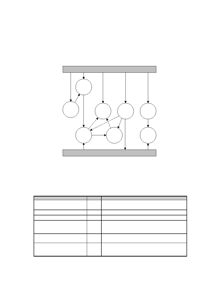
ControLink
TM
TM
86 Realtime Networking Software
35
R
ECEIVING A MESSAGE
is a part of the Driver ISR - when the COM2002x interrupts are examined. The
message received is stored in a Driver queue. Retrieval of this information from the Driver queue is
scheduled by the upper layer software.
N
ETWORK EVENTS
are also processed by the Driver ISR - the driver software is designed to increment a
diagnostic counter associated with a particular network event. A designer may choose an action, that a
real-life system should perform as a result of any network event.
INITIALIZATION
NETWORK
STATUS
RETRIEVE
RECEIVED
DATA
DRIVER
ISR
NETWORK
MAP
QUEUE
MAINTENANCE
PARAMETER
MAINTENANCE
UPPER LAYERS
COM20020
TRANSMIT
MESSAGE
FIGURE 10: D20 LOW LEVEL DRIVER OPERATION
The solid lines indicate the initiator of the D20 Driver software process. The dashed lines indicate the
transfer of control or data to the other D20 Driver processes.
4.4LOW LEVEL DRIVER FUNCTIONS SUMMARY
Function
Type
Description
d20_set_defaults()
service Sets hardware defaults defined by the Driver
Parameters.
d20_get_parameter()
service get value of hardware parameter.
d20_set_parameter()
service Sets a selected parameter to a given value.
d20_init()
service Using the values set by the d20_set_parameter
routine or the default values. Initializes the
COM2002x.
d20_read_packet()
service Checks if there is a new packet in the receive buffer
and moves it to the specified location (buffer).
d20_write_packet()
service Moves data from the specified buffer into the
specified page in the COM2002x RAM for
transmission. Schedule the transmission optionally.

ControLink
TM
TM
86 Realtime Networking Software
36
Function
Type
Description
d20_get_qentry()
service Copies the data from the oldest entry in the receive
queue (internal buffer to D20) into the specified
location.
d20_network_map
service Builds a map of physical ID values on the network.
d20_registers()
service Returns the contents of the COM2002x Read
Registers.
d20_diagnostic()
service Returns the contents of the diagnostic counters.
d20_clear_diag()
service Writes 0 to all diagnostic counters except of the
D20_Retry_Counter - reinitializes it with the number
of retries allowed.
d20_tokens
service Counts the specified number of token rotations.
d20_exit()
service shuts down the node, resets interrupt vectors (if
any), and returns to host.
d20_interrupt()
isr
Main ISR of the Driver - this routine is vectored to.
Issues an EOI sequence - Sets a global flag for the
system.
d20_check_int()
int
Parses the interrupt flags of the COM2002x
(Status Register and Diagnostic Status Register):
(TA) Transmitter Available
(NEW NEXTID) New Next ID
(RECON) Reconfiguration
(EXCNAK) Excessive NAK
(RI) Receiver Inhibited
d20_check_diag()
int
Check if the POR flag was set in the Diagnostic
Status Register. Increment a diagnostic counter.
read_data()
service Copy data from a specified page inside the
COM2002x to the specific buffer.
write_data()
service Copy data from a specified buffer location to the
specified page within the COM2002x.
check_network_status()
int
checks if the network is active and whether there
are other nodes on the network.
4.5CONFIGURABLE PARAMETERS
The COM2002x device driver routines have user-selectable parameters which allow the application
programmer to customize the driver to application-specific or different hardware environments. The
parameters are broken up into two areas: specific to the hardware platform and ARCNET specific. These
parameters are stored in an array called d20_params[ ] and are not programmed into the device until
the d20_init() routine is called. These parameters must be set up prior to calling the driver initialization.
The definitions for each parameter are included in the D20.H file. After initialization, most parameters
should not be modified. A network should have nodes which have the same ARCNET parameters.

ControLink
TM
TM
86 Realtime Networking Software
37
4.5.1HARDWARE PARAMETERS
The hardware parameters determine the following aspects of the network hardware:
�
base address of the COM2002x card
�
type of computer bus (8/16 bit)
�
operating mode of the driver: polled or interrupt
�
type of interrupt controller
�
interrupt level
�
interrupt mask
�
end of interrupt sequence
�
system clock frequency
4.5.2ARCNET PARAMETERS
The ARCNET parameters determine the personality of this node and the characteristics of the network
such as:
�
contents of Interrupt Mask Register
�
number of retries of a transmission
�
ability of the D20 driver to disable transmitter
�
waiting for ACK before returning status of a transmission
�
number of input/output buffers
�
broadcast messages enabled or disabled
�
short and/or long packets enabled or disabled
�
signaling method - backplane or normal
�
network speed, timeout
�
command chaining
�
nPULSE1 driver mode (push-pull or open drain)
�
number of NAKs before interrupt
�
receive all packets mode
�
packet RAM arbitration speed
All nodes connected to the same network should have same settings for the ARCNET parameters.
4.5.3PARAMETER LIST
As part of the D20.H definition file, each of the parameters is defined. The parameter definition defines
which parameter number is associated with the parameter name. It is suggested that the application
programmer use the parameter name and not the parameter number. See the application examples
listed at the end of this manual for an sample use of the parameter definitions.
Parameter
Default
Description
D20_BASE_LSB
0xE0
COM2002x base address of register page Least
Significant Byte. Address of the register page is
the I/O or memory address to which the
COM2002x is mapped. The LSB and MSB make
up the base address for the COM2002x registers.
D20_BASE_MSB
0x02
COM2002x base address of register page Most
Significant Byte.
For combined MSB / LSB parameters the range is
0x0000 - 0xFFFF. The valid values depend on
the host system.

ControLink
TM
TM
86 Realtime Networking Software
38
Parameter
Default
Description
D20_BUS_8_16
8
The bus type determines if the registers offset
from the base address are incremented by 1 or by
2. A value of 8 for an 8 bit bus sets the increment
value to +1 for each register. A value of 16 for a
16 bit bus sets the increment value to +2 for each
register.
Valid values are 8 or 16.
D20_CLK
20
Holds the value of the XTAL oscillator connected
to the COM2002x for future uses for calculating
the necessary timing primitives.
Valid values are 20 or 40
D20_NODE_MODE
2
Specifies how the Node ID value is determined:
1 = Software set: Node ID is stored in
D20_NODE_ID parameter.
2 = Set the node ID to the value determined by
reading the DIP switch at hardware address
BASE + D20_NODE_SW_PORT.
D20_NODE_SW_PORT
8
The node software port is the offset hardware
address of the DIP switch. This offset is added to
the base address of the COM2002x and read to
determine the node ID. This parameter is only
used if selected by the node mode parameter.
Valid values are 0 to 255.
D20_INT_OR_POLL
0
The COM2002x device and driver software can
be used in polled or in interrupt mode The
interrupt mode provides an interrupt handler to
service the interrupt. The interrupt level, type,
mask, and EOI parameters must be properly
configured prior to the driver initialization.
0 = polled mode
1 = interrupt driven mode
D20_INT_LEVEL
3
The interrupt level is assigned at initialization.
The interrupt level is the hardware interrupt vector
number that is connected between the
COM2002x device and the interrupt controller of
your computer.
Valid values are 0 through 7.
D20_INT_MASK
0x21
The interrupt mask is the I/O port address of the
mask byte for the interrupt controller. Valid values
are 0x00 through 0xFF.
The default value is 0x21 for the IBM PC. This
parameter applies for those 80x86 based on the
8259 Interrupt Controller.
D20_INT_EOI
0x20
The interrupt EOI (End Of Interrupt) is the I/O port
address of the EOI byte for the interrupt
controller(8259A). Valid values are 0x00 through
0xFF. This command is necessary for 80x86
processors only.

ControLink
TM
TM
86 Realtime Networking Software
39
Parameter
Default
Description
D20_IMR
0xFF
Mask for the interrupt Mask Register. This
parameter holds the flags that should be
processed by the d20_check_int() function. The
position of the flag is the same as the COM2002x
Interrupt Mask Register.
D20_RETRIES
0
Number of the retries for the transmission before
the transmission of a packet is aborted.
Valid values: 0 - 255
D20_DISABLE_TX
0x00
If this parameter is set to a "yes" (0x01) value
then the D20 driver will disable the transmitter
when the Excessive NAKs interrupt occurs.
0 = do not disable transmitter
1 = disable transmitter
D20_WRITE_ACK
0
Specifies whether the write routine in the driver
waits for a write acknowledgment from the
network hardware before returning the status to
the upper layer.
0 - do not wait for the acknowledgement.
1 - wait for the acknowledgement.
D20_WAIT_TA
0x01
Specifies whether the d20_write_packet() will wait
for the transmitter to become available.
0 = do not wait for the TA bit
1 = wait for the TA bit
D20_IN_BUFFERS
2
The number of input buffers is determined by
setting this parameter. The input buffers start at
the Packet RAM page 0.
It is assumed that all the input (receive) buffers
are contiguous.
If the command chaining mode is chosen, this
parameter should be set to 2.
D20_OUT_BUFFERS
2
The number of output buffers is determined by
setting this parameter. The output buffers follow
the input buffers in the Packet RAM.
It is assumed that all the output (send) buffers are
contiguous.
If the command chaining mode is selected, this
parameter should be set to 2.
D20_BROADCAST
0
The COM2002x has the ability to accept or send
broadcast messages. Broadcast messages are
delivered to every node connected to the
segment of the physical medium.
0 = reception of broadcast packets is not allowed
1 = reception of broadcast packets is allowed
D20_SHORT_LONG
0
The COM2002x device has the ability to receive
short and/or long packets. Short packets have up
to 253 data bytes, while long packets have up to
507 data bytes.
0 - short packets only
1 - short and long packets

ControLink
TM
TM
86 Realtime Networking Software
40
Parameter
Default
Description
D20_CMD_CHAIN
0x00
COM2002x can receive and transmit messages
one by one or in the command chaining mode,
when two Packet RAM pages are scheduled for
receive or transmit at a time.
0x00 - normal mode (one by one)
0x40 - command chaining
Note: this parameter is OR-ed into the
Configuration Register
D20_NET_TIMEOUT
0x18
This parameter holds the bit settings for the ET1
and ET2 bits that reside in the Config Register of
the COM2002x. For the explanation how the
settings of these bits affects the MAC layer of the
network see Section 7 that explains Network
Speed.
Valid values: 0x00, 0x08, 0x10, 0x18
Note: this parameter is OR-ed into the
Configuration Register
D20_BACKPLANE
0x00
The COM2002x supports a backplane mode in
which the device can directly drive the physical
layer or be used with RS-485 type transceivers.
The signaling in the Backplane mode is different
from the standard Dipulse mode.
0x00 = standard, Dipulse mode
0x04 = Backplane mode
Note: this parameter is OR-ed into the
Configuration Register
D20_NODE_ID
0xFF
The node ID is the resulting node address on the
network for this node. The node mode parameter
determines the method for getting the node
address. See the node mode parameter for more
details.
Valid node addresses are 0x01 to 0xFF.
D20_P1MODE
0x00
Specifies whether the driver for the COM2002x
nPULSE1 pin is configured for the Push-Pull
mode or the Open Drain mode. Refer to the
COM2002x ULANC for further detail.
0x00 = Open Drain
0x80 = Push Pull
Note: this parameter is OR-ed into the Setup
Register
D20_FOUR_NAKS
0x00
This flag modifies the FOUR_NAKS bit in the
COM2002x retry register that controls whether 4
NAKS or 128 NAKS to a transmitted point-to-point
message will result in the EXCNAK interrupt.
0x00 = EXCNAK interrupt after 128 NAKS
0x40 = EXCNAK interrupt after 4 NAKS
Note: this parameter is OR-ed into the Setup
Register

ControLink
TM
TM
86 Realtime Networking Software
41
Parameter
Default
Description
D20_ET3
0x00
Modifies an additional Extended Timing variable
(that scales protocol timing by 3). This selection
can be used for short topologies. Refer to the
COM2002x ULANC Data Sheet for further
information on ET3 timing.
0x00 = No scaling of the time-outs
0x20 = Scaling in effect
Note: this parameter is OR-ed into the Setup
Register
D20_RCV_ALL
0x00
This parameter controls the RCV_ALL bit in the
COM2002x Setup Register. If RCV_ALL bit is set,
it enables the node to receive all valid data
packets regardless of their Destination Node ID.
0x00 = receive only packets addressed to this
node or broadcast packets
0x10 = receive all
Note: this parameter is OR-ed into the Setup
Register
D20_NET_SPEED
0x00
The network speed sets the clock prescaler to one
of five network speeds. It holds the settings of
CKP3, CKP2 and CKP1 bits. Refer to Section 7
that describes network timing for further detail.
Note: this parameter is OR-ed into the Setup
Register
D20_SLOW_ARB
0x00
This parameter controls the SLOW_ARB bit in the
COM2002x Setup Register. For the applications
that use the network at the speed greater than 2.5
Mbps (XTAL> 20 MHz) this parameter must be
set.
0x00 = normal arbitration
0x01 = slow arbitration
Note: this parameter is OR-ed into the Setup
Register
4.6D20 DRIVER: DESCRIPTION OF THE FUNCTIONS
This chapter discusses all D20 Driver functions.
4.6.1d20_set_defaults();
R
OUTINE
D
ESCRIPTION
:
This functions is a simple list assignment that gives the default values to the D20 Driver
parameters stored in the d20_params[ ] array. The parameters are initialized to the default
values listed in the Section 4.5.3. Control application should execute this function before
executing d20_init() function.
R
OUTINE
P
ROTOTYPE
:
void d20_set_defaults(void);

ControLink
TM
TM
86 Realtime Networking Software
42
R
OUTINE
P
ARAMETERS
:
none
R
OUTINE
R
ETURN
V
ALUES
:
none
R
OUTINE
E
XAMPLE
:
...
/* set the driver default values */
d20_set_defaults();
...
4.6.2d20_get_parameter()
R
OUTINE
D
ESCRIPTION
:
The get parameter routine is called to retrieve the current value of one of the driver
parameters. The driver parameter name is used as the input parameter to the get parameter
routine. The result or return value from get parameter is the current value of that particular
driver parameter. The input and result values are unsigned char. The list of driver parameter
names are contained in the ARCDEF.H header file.
R
OUTINE
P
ROTOTYPE
:
USIGN8 d20_get_parameter(USIGN8 cmd_par);
R
OUTINE
P
ARAMETERS
:
Parameter
Description
cmd_par
number of a parameter to be returned.
The list of these numbers is available in D20.H file.
R
OUTINE
R
ETURN
V
ALUES
:
Action
Result
for all parameters
value of a parameter defined by the cmd_par
R
OUTINE
E
XAMPLE
:
...
/* get the node id value */
value = d20_get_parameter(D20P_NODE_ID);
...
4.6.3d20_set_parameter()
R
OUTINE
D
ESCRIPTION
:
The set parameter routine is called to change the current value of one of the driver
parameters. The driver parameter name is used as the input parameter along with the new
value to the set parameter routine. This function does not check if the value to be written into
a parameter is valid or not. The list of D20 driver parameters is given in the Section 4.5.3.
The list of driver parameter names are contained in the D20.H header file.
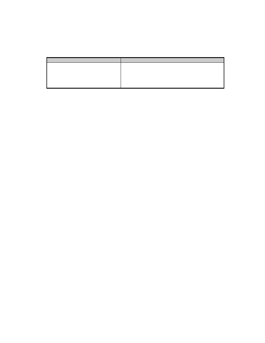
ControLink
TM
TM
86 Realtime Networking Software
43
R
OUTINE
P
ROTOTYPE
:
void d20_set_parameter(USIGN8 cmd_par, USIGN8 data_value);
R
OUTINE
P
ARAMETERS
:
Parameter
Description
cmd_par
number of a parameter to be returned.
The list of these numbers is available in D20.H file.
data_value
the new value for the D20 Driver parameter defined
by the cmd_par
R
OUTINE
R
ETURN
V
ALUES
:
none
R
OUTINE
E
XAMPLE
:
...
/* set the node id to 55H */
d20_set_parameter(D20P_NODE_ID, 0x55);
...
4.6.4 d20_init()
R
OUTINE
D
ESCRIPTION
:
The initialization routine provides the hardware and software initialization of the COM2002x
registers, resets COM2002x, determines the Node ID, joins the network (participates in the
token passing scheme) and enables COM2002x for the reception of a packet. COM2002x
and the driver software are initialized according to the COM2002x Driver parameters (see
Section 4.5).
The D20 Driver parameters may be initialized by the d20_defaults() function or individually,
by the upper layers, using d20_set_parameter() function.
See Section 8 (an example program) for illustration of initializing the D20 Driver.
R
OUTINE
P
ROTOTYPE
:
USIGN8 d20_init(void);
R
OUTINE
P
ARAMETERS
:
none
R
OUTINE
R
ETURN
V
ALUES
:
d20_init() returns the status of the initialization of the driver.

ControLink
TM
TM
86 Realtime Networking Software
44
Action
Result
Reset failed
E_BAD_STATUS
Node alone on the segment
E_NO_TOKEN
E_ONE_NODE
Unrecognized network condition
E_NOT_OK
Duplicated Node ID detected
E_NODE_USED
Initialization done without errors
E_OK
R
OUTINE
E
XAMPLE
:
...
/* initialize the hardware and driver */
status = d20_init();
...
4.6.5d20_read_packet()
R
OUTINE
D
ESCRIPTION
:
Received data retrieval function. After the data has been received by the COM2002x, the
d20_check_int() routine pulls it out of the COM2002x Packet RAM and stores it in the driver
queue called inbuf[ ]. The upper layer or the control application may schedule the retrieval of
the received data from this queue. This retrieval is accomplished by the d20_read_packet()
function. The retrieved data is placed in the system memory at the specified pointer. This
function can be directed to wait for the buffer to be received or read the packet from inbuf[ ]
queue.
The retrieved packet is stored at the specified pointer in the format of the ARCNET packet
(see Section 3.6.3):
Buffer location
Symbol
Description
user_buf[0]
SID
Source ID
user_buf[1]
DID
Destination ID
user_buf[2]
HCNT
0 = indication of a short packet
1 = indication of a long packet
user_buf[3]
LCNT
1 - 252 = short packet count
0 - 256 = long packet count = 256 + count
user_buf[4]
SYSCOD
System Code
user_buf[5]
DATA
LLC packet data
...
...
...
...
user_buf[n]
or
user_buf[256 + n]
DATA
LLC packet data
R
OUTINE
P
ROTOTYPE
:
USIGN8 d20_read_packet(USIGN8 wait_flag, USIGN8 *data_ptr);

ControLink
TM
TM
86 Realtime Networking Software
45
R
OUTINE
P
ARAMETERS
:
Parameter
Description
wait_flag
Specifies whether the function should wait for a
packet reception or get an available packet.
0x00 = do not wait
0x01 = wait
data_ptr
Pointer to a buffer to which the data should be
transferred.
R
OUTINE
R
ETURN
V
ALUES
:
Action
Result
no packet available
E_NO_PACKET
data retrieved correctly
E_OK
R
OUTINE
E
XAMPLE
:
/* user buffer declaration */
USIGN8 user_buf[512];
...
/* wait for packet to be received, then pull it out */
...
status = d20_read_packet(WAIT, user_buf)
if (status == E_OK)
{
/* valid data in the user_buf*/
}
...
4.6.6d20_write_packet()
R
OUTINE
D
ESCRIPTION
:
This function is used for scheduling a transmission of a packet. This function is used by the
upper layers or the control application to schedule a transmission of a packet. This function
will transfer the data provided by the parent software to the COM2002x Packet RAM page
that is available for transmission. If the transmitter is available, this function will then issue a
command to initiate the transmission (see COM2002x ULANC for the description of the
Command Register).
This function will initialize the packet Retry Counter. This is a software mechanism that allows
the D20 Driver to reschedule the sending of a packet as many times as it is specified by the
D20_RETRIES parameter (see Section 4.5).
The data provided in the user buffer to the d20_write_packet() must be of the following
format:
Data Location
Symbol
Description
user_buf[0]
SID
Source ID
user_buf[1]
DID
Destination ID
user_buf[2]
HCNT
0 = indication of a short packet
1 = indication of a long packet
user_buf[3]
LCNT
1 - 252 = short packet count
0 - 256 = long packet count = 256 + count

ControLink
TM
TM
86 Realtime Networking Software
46
user_buf[4]
SYSCOD
System Code
user_buf[5]
DATA
LLC packet data
...
...
...
...
user_buf[n]
or
user_buf[256 + n]
DATA
LLC packet data
R
OUTINE
P
ROTOTYPE
:
USIGN8 d20_write_packet(USIGN8 *data_ptr);
R
OUTINE
P
ARAMETERS
:
Parameter
Description
data_ptr
pointer to the buffer location that contains a packet
to be transmitted
R
OUTINE
R
ETURN
V
ALUES
:
Action
Result
Long packet specified and only
short packets allowed
E_DRIVER_OPTION
The packet size is not allowed by
the ARCNET protocol
E_BAD_PACKET_SIZE
Transmitter is currently busy
E_TX_BUSY
No ACK received
E_TA_NO_ACK
Transmission scheduled without
problems
E_OK
R
OUTINE
E
XAMPLE
:
...
/* send a packet from user_buffer */
status = d20_write_packet (user_buffer)
...
if (status = E_OK)
{
/* Transmission scheduled OK */
}
...
4.6.7d20_get_qentry()
R
OUTINE
D
ESCRIPTION
:
This function takes the oldest entry to the receive queue inbuf[ ] and puts it in the user's
specified location. Queue's head and tail are updated. This routine is used by the
d20_read_packet() function for the retrieval of the received packet.
R
OUTINE
P
ROTOTYPE
:
void d20_get_qentry (USIGN8 * ptr);
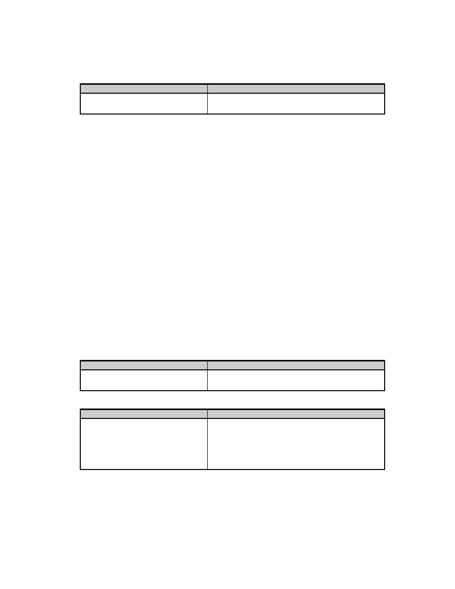
ControLink
TM
TM
86 Realtime Networking Software
47
R
OUTINE
P
ARAMETERS
:
Parameter
Description
ptr
pointer to the buffer where to put the data retrieved
from the COM2002x
R
OUTINE
R
ETURN
V
ALUES
:
none
R
OUTINE
E
XAMPLE
:
/* data buffer declaration */
USIGN8 ptr[512];
...
/* get the packet out of the inbuf[ ] queue*/
d20_get_qentry(ptr);
/* data now available
...
4.6.8d20_network_map()
R
OUTINE
D
ESCRIPTION
:
The network map routine builds a map of the nodes connected to the network. A pointer to a
buffer is passed to the routine and the buffer's bits are set (present) or reset (not present)
depending on if a node is present. The user buffer must be 32 bytes in length. If the node is
present on the network (passing tokens), the corresponding bit to its address is set in the
network map. Bit 0 of the network map (data_ptr[0].0) is illegal.
R
OUTINE
P
ROTOTYPE
:
USIGN8 d20_network_map (USIGN8 *data_ptr);
R
OUTINE
P
ARAMETERS
:
Parameter
Description
data_ptr
pointer to the 32-byte array of 8-bit values that
store the current network map of nodes
R
OUTINE
R
ETURN
V
ALUES
:
Action
Result
network map successfully compiled
E_OK
no active nodes connected to the
medium
E_NO_TOKEN
only one node (this node)
connected and active on the link
E_ONE_NODE
R
OUTINE
E
XAMPLE
:
unsigned char bit_map[32];
/* generate a network bit map */
status = d20_network_map(bit_map);
if(status == E_OK)
{
/* check if node 5 is available */
if ((bit_map[0] & 0x20) != 0)

ControLink
TM
TM
86 Realtime Networking Software
48
{
/* it is part of the network */
}
}
4.6.9d20_registers()
R
OUTINE
D
ESCRIPTION
:
This function copies the contents of the COM2002x Read Registers to the user specified
buffer of 10 bytes (USIGN8). Refer to the COM2002x ULANC Data Sheet for the explanation
of the internal registers.
After the operation is completed, the contents of the buffer is as follows:
Byte number
Description
0
Status Register
1
Diagnostic Status Register - after the reading: 0000 x0x0
2
Address High Register
3
Address Low Register
4
Data Register
5
Configuration Register
6
Tentative ID Register
7
Node ID Register
8
Setup Register
9
Next ID Register
Note that the Diagnostic Status Register bits are reset as a result of the register reading
operation (highlighted entry).
R
OUTINE
P
ROTOTYPE
:
void d20_registers(USIGN8 *p_data_8);
R
OUTINE
P
ARAMETERS
:
Parameter
Description
p_data_8
pointer to the array of 10 bytes that will hold the
COM2002x Read Register values.
R
OUTINE
R
ETURN
V
ALUES
:
none
R
OUTINE
E
XAMPLE
:
...
USIGN8 register[10]
...
/* get current registers */
d20_registers(registers);
...

ControLink
TM
TM
86 Realtime Networking Software
49
4.6.10d20_diagnostic()
R
OUTINE
D
ESCRIPTION
:
This function transfers the state of the diagnostic counters to the specified user buffer.
Diagnostic counters are used to record the number of occurrences of various network events
as well as upper layers' requests.
After the transfer, the buffer holds the following information:
Byte
number
Counter Name
Description
0
D20_RI_CNT
Number of RI interrupts
1
D20_EXNAK_CNT
Number of EXNAK interrupts
2
D20_RECON_CNT
Number of RECON interrupts
3
D20_NNID_CNT
Number of NEW NODE ID interrupts
4
D20_TA_CNT
Number of TA interrupts
5
D20_POR_CNT
Number of POR resets
6
D20_MYRECON_CNT
Number of reconfigurations counted by self
7
D20_RETRY_CNT
Number of retries allowed by system
8
D20_Q_FULL_CNT
Number of times the receive queue was full
9
D20_TX_DONE
Number of successful transmits
10
D20_TX_ERROR
Number of failed transmits
11
D20_INT_GEN
Number of hardware interrupts from the
COM2002x
12
D20_INT_BUSY_CNT
Number of times the ISR was running when the
hardware interrupt came from the COM2002x
R
OUTINE
P
ROTOTYPE
:
void d20_diagnostic(USIGN16 *p_data_16);
R
OUTINE
P
ARAMETERS
:
Parameter
Description
p_data_16
pointer to the array of 13 16-byte (int) entities that
will hold the latest state of the Diagnostic
Counters.
R
OUTINE
R
ETURN
V
ALUES
:
none
R
OUTINE
E
XAMPLE
:
...
USIGN16 counters[13]
...
/* get current diagnostic counters*/
d20_diagnostic(counters);
...

ControLink
TM
TM
86 Realtime Networking Software
50
4.6.11d20_clear_diag()
R
OUTINE
D
ESCRIPTION
:
This function clears (resets to 0) all diagnostic counters except for the D20_RETRIES_CNT
that is reset to the value held by the D20_RETRIES system parameter.
R
OUTINE
P
ROTOTYPE
:
void d20_clear_diag(void);
R
OUTINE
P
ARAMETERS
:
none
R
OUTINE
R
ETURN
V
ALUES
:
none
R
OUTINE
E
XAMPLE
:
...
/* clear diagnostic counters*/
d20_clear_diag();
...
4.6.12d20_tokens()
R
OUTINE
D
ESCRIPTION
:
The tokens routine waits n number of token rotations and then returns to the caller. This
routine can be used for timing functions. The number of rotations can be 1 to 255.
passed parameters: number of token rotations as an unsigned character
R
OUTINE
P
ROTOTYPE
:
void d20_tokens (USIGN8 ntokens);
R
OUTINE
P
ARAMETERS
:
Parameter
Description
ntokens
number of token rotations to wait on the link
R
OUTINE
R
ETURN
V
ALUES
:
none
R
OUTINE
E
XAMPLE
:
...
/* wait 10 token rotations */
d20_tokens(10);
...
4.6.13d20_exit()
R
OUTINE
D
ESCRIPTION
:
The exit routine shuts down the transmitter and receiver of the COM2002x and resets the
interrupt vector (if used) to the original value (stored during the initialization). This routine
must be called before exiting the user application program.

ControLink
TM
TM
86 Realtime Networking Software
51
R
OUTINE
P
ROTOTYPE
:
void d20_exit (void);
R
OUTINE
P
ARAMETERS
:
none
R
OUTINE
R
ETURN
V
ALUES
:
none
R
OUTINE
E
XAMPLE
:
...
/* leave the network and exit */
d20_exit();
...
4.6.14d20_interrupt()
R
OUTINE
D
ESCRIPTION
:
This is the function that is vectored to when the COM2002x generates the hardware interrupt.
The vector to this ISR is stored during the driver initialization. It is recommended that the real-
life control system chains the vector to this ISR rather than replace it. This ISR performs the
following functions:
�
generate the EOI sequence for the host interrupt controller,
�
increment the general counter
�
set a global flag informing the scheduler that there is a network interrupt to be
processed.
R
OUTINE
P
ROTOTYPE
:
void __interrupt __far d20_interrupt (void);
R
OUTINE
P
ARAMETERS
:
none
R
OUTINE
R
ETURN
V
ALUES
:
none
R
OUTINE
E
XAMPLE
: (
INSTALLING THE VECTOR TO THE
d20_interrupt()
)
...
/* define a pointer to the IRQ3 hardware interrupt vector */
#define D20_IRQ3 (USIGN32 __far *)0x2CL
...
/* pointer */
USIGN32 __far *interrupt_vector;
...
/* assign a pointer to the IRQ3 */
interrupt_vector = D20_IRQ3;
/* install the vector to d20_interrupt() at the irq3 location */
*interrupt_vector = (USIGN32 __far *)d20_interrupt;
...
4.6.15d20_check_int()
R
OUTINE
D
ESCRIPTION
:
Interrupt parser. Its function is to process the network related events based on the COM2002x
interrupt bits located in the Status Register and Diagnostic Status Register:

ControLink
TM
TM
86 Realtime Networking Software
52
Bit
Interrupt
Description of Service
RI
Receiver Inhibited
Determine if Command Chaining - if so, clear
Receive Interrupt
Examine the contents of the current Packet RAM
page.
Copy the contents of the Packet RAM page to the
inbuf[ ] queue
Increment the D20_RI_CNT diagnostic counter
Enable next receive page in the Packet RAM
TA
Transmitter Available
Determine if Command Chaining - if so, clear
Transmit Interrupt
Return the status of the broadcast
Return the status of the point-to-point transmission
Increment the D20_TX_DONE and
D20_TX_ERROR diagnostic counters
RECON
Reconfiguration
Increment the D20_RECON_CNT
If the reconfiguration is caused by this node,
increment the D20_MYRECON counter
EXCNAK
Excessive NAK
Clear Excessive NAK interrupt
If the system requires the retry of a packet -
schedule the retransmission
Return the status
Increment D20_EXNAK_CNT diagnostic counter.
NEW
NEXTID
New Next ID
Report the ID of the next node to the upper layers
Increment D20_NNID_CNT diagnostic counter
For explanation of each of these interrupts - refer to the COM2002x ULANC Data Sheet. Note
that the COM2002x will generate the interrupt only when the corresponding bits are set in the
Interrupt Mask Register.
This function can be a part of the ISR d20_interrupt() or can be invoked by the scheduler as a
result of the global flag set the ISR.
The real-life control application may require different actions upon the occurrence of any
network events than those programmed into the d20_check_int() parser. The designer may
want to tailor this parser, inserting the control software in places, where the diagnostic
counters are incremented.
R
OUTINE
P
ROTOTYPE
:
void d20_check_int (void);
R
OUTINE
P
ARAMETERS
:
none
R
OUTINE
R
ETURN
V
ALUES
:
None

ControLink
TM
TM
86 Realtime Networking Software
53
R
OUTINE
E
XAMPLE
:
...
/* this code will continually parse the COM2002x interrupts */
while(TRUE)
{
d20_check_int();
}
...
4.6.16d20_check_diag()
R
OUTINE
D
ESCRIPTION
:
This function checks if the POR (Power on Reset) bit in the Diagnostic Status Register is set.
It is a separate function from the d20_check_int() because this event occurs only once
during the particular network session.
As a result of this routine the D20_POR_CNT diagnostic counter is incremented.
A designer may choose to remove this code from the final application if checking for this
status is not required in the real-life control application.
R
OUTINE
P
ROTOTYPE
:
void d20_check_diag (void);
R
OUTINE
P
ARAMETERS
:
none
R
OUTINE
R
ETURN
V
ALUES
:
none
4.6.17read_data()
R
OUTINE
D
ESCRIPTION
:
A low level routine, it transfers the specified number of bytes from the COM2002x ULANC
Packet RAM page and offset to the location specified by the calling routine. D20 driver uses
this routine to transfer the data from COM2002x to the driver's receive queue inbuf[ ].
R
OUTINE
P
ROTOTYPE
:
void read_data ( USIGN8 page,
USIGN8 offset,
USIGN8 count,
USIGN8 shortlong,
USIGN8 *user_buffer);

ControLink
TM
TM
86 Realtime Networking Software
54
R
OUTINE
P
ARAMETERS
:
Parameter
Description
page
page number of the COM2002x Packet RAM.
These are 512-byte pages. The valid numbers are
0, 1, 2, 3
offset
offset from the beginning of the page specified by
the page parameter
count
number of bytes to read from the Packet RAM
shortlong
specifies if the amount of data exceeds the length
of a short packet (253 bytes)
user_buffer
pointer to the location, to which the data from the
Packet RAM must be copied.
R
OUTINE
R
ETURN
V
ALUES
:
none
R
OUTINE
E
XAMPLE
:
/*
after the reset, read two bytes from the beginning of the packet ram
and determine if they are 0xD1 and the node address (0xfe)
abandon the reading after 1000 tries
*/
/* user buffer of 2 bytes */
USIGN8 buffer[2] = {0, 0};
int click = 0;
/* read loop */
while((buffer[0] != 0xD1) || (buffer[1] != 0xFE))
{
/* read from page =0, offset = 0, 2 bytes, place it in the buffer[ ] array*/
read_data(0, 0, 2, 0, buffer);
DELAYMS(10);
if(++click > 1000)
{
return(E_BAD_STATUS);
}
}
4.6.18write_data()
R
OUTINE
D
ESCRIPTION
:
This function transfers the data from the location inside host system memory into the packet memory (page)
inside the COM2002x ULANC. The specified number of bytes is transferred from the user buffer into the
specified page/offset location of the COM2002x Packet RAM.
R
OUTINE
P
ROTOTYPE
:
void write_data( USIGN8 page,
USIGN8 offset,
USIGN8 count,
USIGN8 ShortLong,
USIGN8 *user_buffer);

ControLink
TM
TM
86 Realtime Networking Software
55
R
OUTINE
P
ARAMETERS
:
Parameter
Description
page
page number of the COM2002x Packet RAM.
These are 512-byte pages. The valid numbers are
0, 1, 2, 3
offset
offset from the beginning of the page specified by
the page parameter
count
number of bytes to write to the Packet RAM
shortlong
specifies if the amount of data exceeds the length
of a short packet (253 bytes)
user_buffer
pointer to the location, from which the data to the
Packet RAM must be copied.
R
OUTINE
R
ETURN
V
ALUES
:
none
R
OUTINE
E
XAMPLE
:
...
/* write two bytes into the page 0. offset 0, from the user_buffer[ ] */
USIGN8 user_buffer[2] = {1, 2};
...
write_data(0, 0, 2, user_buffer);
...
4.6.19check_network_status()
R
OUTINE
D
ESCRIPTION
:
This is an auxiliary function to check whether the MAC layer (network) is alive, tokens are
passed or the medium is undergoing a reconfiguration.
R
OUTINE
P
ROTOTYPE
:
USIGN8 check_network_status(void);
R
OUTINE
P
ARAMETERS
:
none
R
OUTINE
R
ETURN
V
ALUES
:
Action
Result
Token seen but reconfiguration
occurred (single node network)
E_ONE_NODE
The token bit is not being set (the
node does not recognize any
tokens)
E_NO_TOKEN
The tokens are being passed, there
is at least one other node on the
network
E_OK

ControLink
TM
TM
86 Realtime Networking Software
56
R
OUTINE
E
XAMPLE
:
/* check if the network is operational */
USIGN8 status;
...
switch(check_network_status())
{
case E_OK:
/* network ok */
break;
case E_NO_TOKEN:
/* process for no token */
break;
case E_ONE_NODE:
/* alone on the network */
break;
default:
break;
}
...

ControLink
TM
TM
86 Realtime Networking Software
57
5.LIST OF ERROR CODES RETURNED
5.1CODES RETURNED BY THE D20.C DRIVER FUNCTIONS
Name
Dec
Hex
Description
E_OK 0
0
0x00
operation successful
E_NO_PARAMETERS
1
0x01
setup parameters not initialized
E_BAD_STATUS
2
0x02
ARCNET not operational
E_NOT_INITED
3
0x03
ARCNET was never initialized
E_BAD_COMMAND
4
0x04
invalid command value
E_BAD_PARAMETER
5
0x05
invalid parameter value
E_BAD_DATA
6
0x06
invalid data value
E_NO_PACKET
7
0x07
no packet available
E_NO_TOKEN 8
8
0x08
no token seen
E_BAD_PACKET_SIZE
9
0x09
bad packet size for packet type
E_TX_BUSY
10
0x0A
transmitter busy
E_ACK
11
0x0B
write acknowledged
E_ABORT
12
0x0C
write aborted
E_DUPID
13
0x0D
duplicate ID detected on the network
segment
E_ONE_NODE
14
0x0E
only one node on the network
E_NODE_USED
15
0x0F
node address is used or 255 nodes
connected to the segment
E_QFULL
16
0x10
queue is full
E_NAK_NO_TX
17
0x11
cannot transmit a packet due to the
NAKs to FBEs
E_DRIVER_OPTION
18
0x12
driver configuration does not permit
the service
E_TA_NO_ACK
19
0x13
TA bit set but not TMA bit
E_NOT_OK
255
0xFF
bad status
5.2CODES RETURNED BY THE LLC1.C FUNCTIONS
Name
Dec
Hex
Description
E_UP
30
0x1E
Station state: operational
E_DOWN
31
0x1F
Station state: down
E_NO_SAP
32
0x20
SAP selected does not exist

ControLink
TM
TM
86 Realtime Networking Software
58
6.NETWORK SPEED
ControLink86 is primarily designed to operate with the default network speed and timeout values for the
COM2002x ULANC controllers. The network speed and timeout concepts are explained in the
COM2002x ULANC Data Sheets. The default values are those which are the original values for the
ARCNET Local Area Network Standard: ATA/ANSI 878.1.
COM2002x permits the operation of the physical medium at the following speeds / timeout / timer
selections. The network speed is a function of the following factors:
�
Crystal oscillator value (20MHz or 40MHz)
�
Setting of the Clock Prescaler bits CKP3, CKP2, CKP1 which divide the oscillator frequency and
yield the effective network speed (baud rate)
�
Setting of the Extended Timeout bits ET1, ET2 and separately ET3
The above circumstances influence the behavior of the ARCNET network core, and more specifically its
Response Timer, Idle Timer and Reconfiguration Timer.
ET2
ET1
Divisor
Speed
Response Timer
[us]
Idle Timer
[us]
Reconfiguration Timer
[ms]
*
5
mbps
37.35
41
420
1
1
8
2.5
mbps
74.7
82
840
16
1.25
mbps
149.4
164
1680
32
625
kbps
298.4
328
3360
64
312.5
kbps
596.8
656
6920
128
156.25
kbps
1193.6
1312
13440
*
5
mbps
74.7
82
840
1
0
8
2.5
mbps
298.4
328
1680
16
1.25
mbps
596.8
656
3360
32
625
kbps
1193.6
1312
6920
64
312.5
kbps
2387.2
2624
13440
128
156.25
kbps
4774.4
5248
26880
*
5
mbps
298.4
328
840
0
1
8
2.5
mbps
596.8
656
1680
16
1.25
mbps
1193.6
1312
3360
32
625
kbps
2387.2
2624
6920
64
312.5
kbps
4774.4
5248
13440
128
156.25
kbps
9548.8
10496
26880
*
5
mbps
596.8
656
840
0
0
8
2.5
mbps
1193.6
1312
1680
16
1.25
mbps
2387.2
2624
3360
32
625
kbps
4774.4
5248
6920
64
312.5
kbps
9548.8
10496
13440
128
156.25
kbps
19097.6
20992
26880
The table above summarizes the values of the timers for each network speed. The shaded field is the
default network speed

ControLink
TM
TM
86 Realtime Networking Software
59
The timing primitives are provided in the MSC.H file. These are:
�
DELAYMS(number_of_milliseconds)
�
DELAYUS(number_of_microseconds).
D20 driver must wait for the expiration of the above timers in cases of:
�
Reset
�
Reconfiguration
�
Token timing
The timing macros are provided for several platforms based on the PC ISA bus. The designer of a real-
life control application is responsible for making sure that these macros hold for the physical system that
is in use.

ControLink
TM
TM
86 Realtime Networking Software
60
7.SAMPLE PROGRAM APP_INT.C
The following listing is the actual program distributed with ControLink86, and it is an interrupt based
demonstration application. This is the file APP_INT.C
/*********************************************************************/
/*-------------------------------------------------------------------*/
/* STANDARD MICROSYSTEMS CORPORATION */
/*-------------------------------------------------------------------*/
/* Module: ControLink Test Program */
/* Filename: app_int.c */
/* Description: Example program to exercise ControLink functions */
/* Uses the interrupt mode of D20 driver */
/* Compiler: Microsoft C ver. 7.00 (Visual C++) */
/* Target system: PC-AT platform */
/* Target O.S.: MS-DOS + ANSI.SYS loaded */
/*********************************************************************/
/*=== INCLUDE FILES =======================================================*/
/* standard libraries */
#include <stdio.h>
#include <stdlib.h>
#include <conio.h>
#include <dos.h>
#include <string.h>
/* compiler specific includes */
#include <msc.h>
/* arcnet specific defines */
#include <arcdef.h>
#include <llc.h>
/* function declarations */
#include <d20.h>
#include <llc1.h>
/*=== DEFINITIONS =========================================================*/
/* display */
#define CLRSCR printf("\x1B[2J") /* clear screen escape sequence */
/*=== CHARACTER ARRAYS ====================================================*/
static char *par_names[ ] = {
"D20_BASE_LSB",
"D20_BASE_MSB",
"D20_BUS_8_16",
"D20_CLOCK_RATE",
"D20_NODE_MODE",
"D20_SW_PORT",
"D20_INT_OR_POLL",
"D20_INT_LEVEL",
"D20_INT_MASK",
"D20_INT_EOI",
"D20_IMR",
"D20_RETRIES",
"D20_DISABLE_TX",
"D20_WRITE_ACK",
"D20_WAIT_TA",
"D20_IN_BUFFERS",
"D20_OUT_BUFFERS",
"D20_BROADCAST",
"D20_SHORT_LONG",
"D20_CMD_CHAIN",
"D20_NET_TIMEOUT",
"D20_BACKPLANE",
"D20_NODE_ID",
"D20_P1MODE",

ControLink
TM
TM
86 Realtime Networking Software
61
"D20_FOUR_NAKS",
"D20_ET3",
"D20_RCV_ALL",
"D20_NET_SPEED",
"D20_SLOW_ARB"
};
static char *status_str[ ] = {
"E_OK",
"E_NO_PARAMETERS",
"E_BAD_STATUS",
"E_NOT_INITED",
"E_BAD_COMMAND",
"E_BAD_PARAMETER",
"E_BAD_DATA",
"E_NO_PACKET",
"E_NO_TOKEN",
"E_BAD_PACKET_SIZE",
"E_TX_BUSY",
"E_ACK",
"E_ABORT",
"E_DUPID",
"E_ONE_NODE",
"E_NODE_USED",
"E_QFULL",
"E_NAK_NO_TX",
"E_DRIVER_OPTION",
"E_TA_NO_ACK",
"E_NOT_OK"
};
/*=== GLOBAL DECLARATIONS =================================================*/
/* SAPs */
struct LLC_MSG SAP[MAX_SAPS];
USIGN8 SAPBUF[MAX_SAPS][MAX_SAPBUF];
unsigned int sizeof_sb[MAX_SAPS];
unsigned int numof_saps = MAX_SAPS;
unsigned char sap_type[MAX_SAPS];
unsigned char netmap[32];
USIGN8 regs[SIZEOF_REGISTERS];
USIGN16 diag_cntr[SIZEOF_DIAG_CNT];
extern USIGN8 int_flag;
extern USIGN8 rx_flag;
/*=== FUNCTION PROTOTYPES =================================================*/
void prompt(void);
void chk_saps(void);
void parse_indication(unsigned char, unsigned char);
unsigned char send_pkt(void);
void net_init(void);
void display_parameters(void);
void init_sap(void);
void display_netmap(void);
void change_sap(void);
void show_saps(void);
/*=== CODE ================================================================*/
void main(void)
{
int dummx = 'r';
unsigned char status;
/*=============*/
/* PREPARATION */
/*=============*/
CLRSCR;
printf("TEST11 for %s\n", platform_string);
prompt();

ControLink
TM
TM
86 Realtime Networking Software
62
CLRSCR;
net_init();
prompt();
CLRSCR;
/* show all active nodes on the link */
display_netmap();
prompt();
CLRSCR;
/* tell controlink to activate the SAPs, use a 0 DSAP to indicate internal activity */
init_sap();
prompt();
CLRSCR;
/*===========*/
/* TEST CODE */
/*===========*/
printf("Enter:\n");
printf(" <t> to transmit a data packet from a SAP to a SAP\n");
printf(" <c> to change configuration of a SAP\n");
printf(" <d> to display the configuration of all SAPs\n");
printf(" <e> to exit this program\n");
printf("\n");
while(TRUE)
{
/* service the interrupts */
if(int_flag)
{
DISABLE;
d20_check_int();
int_flag = FALSE;
if(rx_flag)
{
llc1_service();
rx_flag = FALSE;
}
ENABLE;
}
/* check saps if any service received */
chk_saps();
/* check for other services */
if(kbhit())
{
dummx = _getch();
CLRSCR;
printf("Enter:\n");
printf(" <t> to transmit a packet from a SAP to a SAP\n");
printf(" <c> to change configuration of a SAP\n");
printf(" <d> to display the configuration of all SAPs\n");
printf(" <e> to exit this program\n");
printf("\n");
}
/* send data */
if((dummx == 't') || (dummx == 'T'))
{
status = send_pkt();
printf("Transmission scheduled with the status: %s\n",
status_str[status]);
}
/* change data in a SAP buffer */

ControLink
TM
TM
86 Realtime Networking Software
63
else if((dummx == 'c') || (dummx == 'C'))
{
change_sap();
}
/* display configuration of all SAPs*/
else if((dummx == 'd') || (dummx == 'D'))
{
show_saps();
}
/* exit */
else if((dummx == 'e') || (dummx == 'E'))
{
d20_exit();
exit(-1);
}
dummx = 0x00;
}
} /* end of main(..) */
/****************************************************************************
* FUNCTION NAME: prompt
*
* DESCRIPTION : prompts operator to exit or continue
*
* RETURN VALUE : none
***************************************************************************/
void prompt(void)
{
char dummy1[10];
/* continue or exit */
printf("\nHit <E> to exit or <Return> to continue: ");
gets(&dummy1[0]);
printf("\n");
fflush(stdin);
if ((dummy1[0] == 'e')||(dummy1[0] == 'E'))
{
exit(0);
}
} /* end of prompt(..) */
/****************************************************************************
* FUNCTION NAME: chk_saps
*
* DESCRIPTION : check incoming packet
*
* RETURN VALUE : none
***************************************************************************/
void chk_saps(void)
{
USIGN8 status;
unsigned char i;
for(i = 0; i < numof_saps; i++)
{
status = llc1_indication((USIGN8)(i + 1));
parse_indication(status, i);
}
} /* end of chk_saps(..) */
/****************************************************************************
* FUNCTION NAME: parse_indication
*
* DESCRIPTION : check the control field of the incoming packet
*
* RETURN VALUE : none
***************************************************************************/
void parse_indication(unsigned char pkt_type, unsigned char sapid)
{
unsigned int j;

ControLink
TM
TM
86 Realtime Networking Software
64
switch(pkt_type)
{
case NO_INDICATION:
break;
case UNITDATA_INDICATION:
{
printf("\nSAP %d received %d bytes: { ", (sapid + 1), ((SAP[sapid].msbcount << 8) +
SAP[sapid].lsbcount));
for(j = 0; j < sizeof_sb[sapid]; j++)
{
if((j < 3) || (j > (sizeof_sb[sapid] - 3)))
{
printf("%02x ", SAPBUF[sapid][j]);
}
else if(j < 4)
{
printf("... ");
}
}
printf("}\n");
break;
}
case XID_INDICATION:
{
printf("XID query from SAP %d\n", sapid);
break;
}
case TEST_INDICATION:
{
printf("Link TEST frame received from SAP %d\n", sapid);
break;
}
case DISC_INDICATION:
{
printf("Received Disconnect Command\n");
break;
}
case DISC_CONFIRM:
{
printf("Disconnect Confirmation Received\n");
break;
}
}
} /* end of parse_indication(..) */
/****************************************************************************
* FUNCTION NAME: send_pkt
*
* DESCRIPTION : schedule a packet to be sent
*
* RETURN VALUE : none
***************************************************************************/
unsigned char send_pkt(void)
{
unsigned char status;
USIGN8 destination_node;
USIGN8 ssapidx;
USIGN8 dsapidx;
unsigned char once_many;
char dummy[10];
/* get the node address to send the data to */
printf("Enter the destination node address\n");
printf("<0x01 - 0xFF> for individual or <0x00> for broadcast: ");
gets(&dummy[0]);
fflush(stdin);
sscanf(&dummy[0], "%x", &destination_node);

ControLink
TM
TM
86 Realtime Networking Software
65
/* get the sap to send from */
printf("Enter the SAP number to send the data from: ");
gets(&dummy[0]);
fflush(stdin);
sscanf(&dummy[0], "%d", &ssapidx);
/* adjust ssapidx for the index to the arrays */
if(ssapidx == 0)
{
printf("SAP 0 is reserved - use another!\n");
return(E_NOT_OK);
}
else
{
ssapidx--;
}
/* get the sap to send from */
printf("Enter the SAP number to send the to: ");
gets(&dummy[0]);
fflush(stdin);
sscanf(&dummy[0], "%d", &dsapidx);
/* check if continual sending */
printf("Enter:\n");
printf(" <o> to transmit once\n");
printf(" <c> to transmit continually\n");
printf("\n");
gets(&dummy[0]);
fflush(stdin);
scanf(&dummy[0], "%d", &once_many);
if((dummy[0] == 'o') || (dummy[0] == 'O'))
{
/* data request */
SAP[ssapidx].dstation = (USIGN8)destination_node;
SAP[ssapidx].msbcount = (USIGN8)((sizeof_sb[ssapidx] & 0xFF00) >> 8);
SAP[ssapidx].lsbcount = (USIGN8)(sizeof_sb[ssapidx] & 0x00FF);
SAP[ssapidx].msgptr = &SAPBUF[ssapidx][0];
status = llc1_request((USIGN8)(ssapidx + 1), dsapidx, DATA_REQUEST, &SAP[ssapidx]);
}
else if((dummy[0] == 'c') || (dummy[0] == 'C'))
{
while(TRUE)
{
SAP[ssapidx].dstation = (USIGN8)destination_node;
SAP[ssapidx].msbcount = (USIGN8)((sizeof_sb[ssapidx] & 0xFF00) >> 8);
SAP[ssapidx].lsbcount = (USIGN8)(sizeof_sb[ssapidx] & 0x00FF);
SAP[ssapidx].msgptr = &SAPBUF[ssapidx][0];
status = llc1_request((USIGN8)(ssapidx + 1), dsapidx, DATA_REQUEST, &SAP[ssapidx]);
/* if keyboard hit - return */
if(kbhit())
{
return(status);
}
}
}
else
{
printf("\n\nInvalid selection!\n");
return(E_NOT_OK);
}
return(status);
} /* end of send_pkt(..) */
/****************************************************************************
* FUNCTION NAME: net_init
*
* DESCRIPTION : initializes the network
*

ControLink
TM
TM
86 Realtime Networking Software
66
* RETURN VALUE : none
***************************************************************************/
void net_init(void)
{
unsigned char init_status;
char dummy[10];
USIGN8 temp_param;
USIGN8 i;
FILE *params;
/* select the configuration parameters for the D20.C */
printf("Enter:\n");
printf(" <d> for the default parameters - in D20.C\n");
printf(" <m> for manual setting of the parameters\n");
printf(" <f> to initialize parameters from the file D20.PAR\n");
printf(" <e> to exit this program\n");
gets(&dummy[0]);
printf("\n");
fflush(stdin);
/* default parameters in D20.C */
if((dummy[0] == 'd') || (dummy[0] == 'D'))
{
d20_set_defaults();
}
/* enter parameters manually */
else if((dummy[0] == 'm') || (dummy[0] == 'M'))
{
for(i = 0; i <= D20P_SLOW_ARB; i++)
{
printf("%s: ", par_names[i] );
gets(&dummy[0]);
fflush(stdin);
sscanf(&dummy[0], "%x", &temp_param);
d20_set_parameter(i, temp_param);
}
}
/* read parameters from D20.PAR file */
else if((dummy[0] == 'f') || (dummy[0] == 'F'))
{
if((params = fopen( "D20.PAR", "r" )) == NULL)
{
printf( "ERROR The file 'D20.PAR' was not opened. Exiting\n");
d20_exit();
exit(-1);
}
else
{
for(i = 0; i <= D20P_SLOW_ARB; i++)
{
fscanf(params, "%02x", &temp_param);
d20_set_parameter(i, temp_param);
}
fclose(params);
}
}
/* exit */
else if((dummy[0] == 'e') || (dummy[0] == 'e'))
{
exit(-1);
}
else
{
printf("\nInvalid selection - exiting!\n");
exit(-1);
}
CLRSCR;
/* display what is about to be configured */
display_parameters();
printf("\nEnter:\n");
printf(" <y> to keep the above parameters\n");

ControLink
TM
TM
86 Realtime Networking Software
67
printf(" <e> to exit this program\n");
gets(&dummy[0]);
printf("\n");
fflush(stdin);
/* initialize the hardware with the given parameters */
if((dummy[0] == 'y') || (dummy[0] == 'Y'))
{
/* initialize hardware */
init_status = d20_init();
}
else if((dummy[0] == 'e') || (dummy[0] == 'e'))
{
exit(-1);
}
else
{
printf("\nInvalid selection - exiting!\n");
exit(-1);
}
/* check the result of the initialization */
if(init_status != E_OK)
{
printf("\nInitialization failed, ERROR CODE = %s\n", status_str[init_status]);
printf("Exiting\n");
d20_exit();
exit(-1);
}
CLRSCR;
printf("Initialization OK\n\n");
display_parameters();
} /* end of net_init(..) */
/****************************************************************************
* FUNCTION NAME: display_parameters
*
* DESCRIPTION : gets the parameters from d20_params and displays them
*
* RETURN VALUE : none
***************************************************************************/
void display_parameters(void)
{
printf("D20_BASE_LSB D20_BASE_MSB D20_BUS_8_16 D20_CLK D20_NODE_MODE D20_SW_PORT\n");
printf(" %02x %02x %02x %02x %02x %02x\n",
d20_get_parameter(D20P_BASE_LSB), d20_get_parameter(D20P_BASE_MSB),
d20_get_parameter(D20P_BUS_8_16), d20_get_parameter(D20P_CLK),
d20_get_parameter(D20P_NODE_MODE), d20_get_parameter(D20P_NODE_SW_PORT));
printf("D20_INT_OR_POLL D20_INT_LEVEL D20_INT_MASK D20_INT_EOI D20_IMR\n");
printf(" %02x %02x %02x %02x %02x\n",
d20_get_parameter(D20P_INT_OR_POLL), d20_get_parameter(D20P_INT_LEVEL),
d20_get_parameter(D20P_INT_MASK), d20_get_parameter(D20P_INT_EOI),
d20_get_parameter(D20P_IMR));
printf("D20_RETRIES D20_DISABLE_TX D20_WRITE_ACK\n");
printf(" %02x %02x %02x\n",
d20_get_parameter(D20P_RETRIES), d20_get_parameter(D20P_DISABLE_TX),
d20_get_parameter(D20P_WRITE_ACK));
printf("D20_IN_BUFFERS D20_OUT_BUFFERS\n");
printf(" %02x %02x\n",
d20_get_parameter(D20P_IN_BUFFERS),
d20_get_parameter(D20P_OUT_BUFFERS));
printf("D20_BROADCAST D20_SHORT_LONG\n");
printf(" %02x %02x\n",
d20_get_parameter(D20P_BROADCAST),
d20_get_parameter(D20P_SHORT_LONG));
printf("D20_CMD_CHAIN D20_NET_TIMEOUT D20_BACKPLANE\n");

ControLink
TM
TM
86 Realtime Networking Software
68
printf(" %02x %02x %02x\n",
d20_get_parameter(D20P_CMD_CHAIN),
d20_get_parameter(D20P_NET_TIMEOUT),
d20_get_parameter(D20P_BACKPLANE));
printf("D20_NODE_ID = %02x\n", d20_get_parameter(D20P_NODE_ID));
printf("D20_P1MODE D20_FOUR_NAKS D20_ET3 D20_RCV_ALL D20_NET_SPEED D20_SLOW_ARB\n");
printf(" %02x %02x %02x %02x %02x %02x\n",
d20_get_parameter(D20P_P1MODE), d20_get_parameter(D20P_FOUR_NAKS),
d20_get_parameter(D20P_ET3), d20_get_parameter(D20P_RCV_ALL),
d20_get_parameter(D20P_NET_SPEED), d20_get_parameter(D20P_SLOW_ARB));
} /* end of display_parameters(..)
/****************************************************************************
* FUNCTION NAME: init_sap
*
* DESCRIPTION : initialize llc driver and all declared saps
*
* RETURN VALUE : none
***************************************************************************/
void init_sap(void)
{
char dummy[10];
unsigned char sap_status;
unsigned char temp;
unsigned int j;
USIGN8 i;
/* initialize SAPS */
printf("Enter:\n");
printf(" <d> for the default size of 8 SAPs - 16 bytes per each SAP buffer\n");
printf(" <m> for manual setting of the SAP buffer sizes\n");
printf(" <e> to exit this program\n");
gets(&dummy[0]);
printf("\n");
fflush(stdin);
if((dummy[0] == 'm') || (dummy[0] == 'M'))
{
/* get number of SAPs for this program */
printf("\nEnter number of SAPs for this application: ");
gets(&dummy[0]);
printf("\n\n");
fflush(stdin);
sscanf(&dummy[0], "%d", &numof_saps);
for(i = 0; i < numof_saps; i++)
{
printf("Enter the size of buffer for SAP %d: ", (i + 1));
gets(&dummy[0]);
fflush(stdin);
sscanf(&dummy[0], "%d", &sizeof_sb[i]);
printf("Enter the formatting character of the SAPBUF %d: ", (i + 1));
gets(&dummy[0]);
printf("\n");
fflush(stdin);
sscanf(&dummy[0], "%x", &temp);
for(j = 0; j < sizeof_sb[i]; j++)
{
SAPBUF[i][j] = temp;
}
}
}
else if((dummy[0] == 'd') || (dummy[0] == 'D'))
{
numof_saps = 8;
for(i = 0; i < numof_saps; i++)
{
sizeof_sb[i] = 16;

ControLink
TM
TM
86 Realtime Networking Software
69
for(j = 0; j < 16; j++)
{
SAPBUF[i][j] = (USIGN8)((i + 1) << 4);
}
}
}
else if((dummy[0] == 'e') || (dummy[0] == 'e'))
{
exit(-1);
}
else
{
printf("\nInvalid selection - exiting!\n");
exit(-1);
}
/* link LLC structure to SAP buffers */
for (i = 0; i < numof_saps; i++)
{
SAP[i].msgptr = &SAPBUF[i][0];
}
/* initialize LLC driver */
sap_status = llc1_request(0, 0, ENABLE_WITHOUT_DUP_ADDR_CHECK, &SAP[0]);
if(sap_status != E_OK)
{
printf("ERROR - going online!\n");
}
/* activate SAPS */
for(i = 0; i < numof_saps; i++)
{
sap_status = llc1_request((USIGN8)(i + 1), 0, SAP_ACTIVATION_REQUEST, &SAP[i]);
if(sap_status != E_OK)
{
printf("ERROR - activating SAP %d\n", (i + 1));
}
else
{
printf("SAP %d is on line. SAP %d data: { ", (i + 1), (i + 1));
for(j = 0; j < sizeof_sb[i]; j++)
{
if((j < 3) || (j > (sizeof_sb[i] - 3)))
{
printf("%02x ", SAPBUF[i][j]);
}
else if(j < 4)
{
printf("... ");
}
}
printf("}\n");
}
}
} /* end of init_sap(..) */
/****************************************************************************
* FUNCTION NAME: display_netmap
*
* DESCRIPTION : displays formatted output of the active nodes
*
* RETURN VALUE : none
***************************************************************************/
void display_netmap(void)
{
int i;
int j;
char net_status;
printf("\nGetting the network map - wait!\n");

ControLink
TM
TM
86 Realtime Networking Software
70
net_status = d20_network_map(netmap);
/* display network map */
printf("\nNetwork Map:\n\n");
for(i = 0; i < 32; i ++)
{
for(j = 0; j < 8; j++)
{
if(netmap[i] & (1 << j))
{
printf("%02x, ", ((i * 8) + j));
}
}
}
printf("\n\n");
if((net_status != E_OK))
{
printf("Bad network, status = %s\n", status_str[net_status]);
printf("Exiting ControLink\n");
exit(-1);
}
} /* end of display_netmap(..)
/****************************************************************************
* FUNCTION NAME: change_sap
*
* DESCRIPTION : changes data in a selected SAP buffer
*
* RETURN VALUE : none
***************************************************************************/
void change_sap(void)
{
char dummy[10];
USIGN8 sapidx;
USIGN8 temp;
USIGN8 sap_status;
unsigned int j;
unsigned char init_flag = FALSE;
/* get the sap number to change */
printf("\nEnter the SAP number to change: ");
gets(&dummy[0]);
fflush(stdin);
sscanf(&dummy[0], "%d", &sapidx);
/* convert the sap number into the array index */
sapidx--;
printf("\nEnter:\n");
printf(" <y> to change configuration of SAP %d\n", (sapidx + 1));
printf(" <n> to keep old configuration of SAP %d\n", (sapidx + 1));
printf(" <e> to exit to main menu\n");
gets(&dummy[0]);
printf("\n");
fflush(stdin);
if((dummy[0] == 'y') || (dummy[0] == 'Y'))
{
/* set init flag */
init_flag = TRUE;
/* take the SAP off line */
sap_status = llc1_request((USIGN8)(sapidx + 1), 0, SAP_DEACTIVATION_REQUEST,
&SAP[sapidx]);
if(sap_status == E_OK)
{
printf("SAP %d is deactivated.\n", (sapidx + 1));
}
else
{
printf("ERROR - deactivating SAP %d.\n", (sapidx + 1));

ControLink
TM
TM
86 Realtime Networking Software
71
return;
}
/* enter new configuration */
printf("\nEnter the new size of SAP %d: ", (sapidx + 1));
gets(&dummy[0]);
fflush(stdin);
sscanf(&dummy[0], "%d", &sizeof_sb[sapidx]);
}
else if((dummy[0] == 'e') || (dummy[0] == 'E'))
{
return;
}
else if((dummy[0] == 'n') || (dummy[0] == 'N'))
{
printf("\nSAP %d retains its old parameters\n", (sapidx + 1));
}
/* get the formatting character */
printf("\nEnter the formatting character of the SAPBUF %d: ", (sapidx + 1));
gets(&dummy[0]);
printf("\n");
fflush(stdin);
sscanf(&dummy[0], "%x", &temp);
/* fill the SAP buffer */
for(j = 0; j < sizeof_sb[sapidx]; j++)
{
SAPBUF[sapidx][j] = temp;
}
if(init_flag == TRUE)
{
/* activate SAP with the new parameters */
sap_status = llc1_request((USIGN8)(sapidx + 1), 0, SAP_ACTIVATION_REQUEST, &SAP[sapidx]);
if(sap_status != E_OK)
{
printf("ERROR - activating SAP %d\n", (sapidx + 1));
}
else
{
printf("SAP %d is on line. SAP %d has %d bytes: { ", (sapidx + 1), (sapidx + 1),
sizeof_sb[sapidx]);
for(j = 0; j < sizeof_sb[sapidx]; j++)
{
if((j < 3) || (j > (sizeof_sb[sapidx] - 3)))
{
printf("%02x ", SAPBUF[sapidx][j]);
}
else if(j < 4)
{
printf("... ");
}
}
printf("}\n");
}
}
else
{
/* display the contents of the SAP buffer */
printf("SAP %d new data, %d bytes: { ", (sapidx + 1), sizeof_sb[sapidx]);
for(j = 0; j < sizeof_sb[sapidx]; j++)
{
if((j < 3) || (j > (sizeof_sb[sapidx] - 3)))
{
printf("%02x ", SAPBUF[sapidx][j]);
}
else if(j < 4)
{
printf("... ");
}
}
printf("}\n");

ControLink
TM
TM
86 Realtime Networking Software
72
}
} /* end of change_sap(..) */
**********************************************************************/
* FUNCTION NAME: show_saps
*
* DESCRIPTION : shows the size and contents of local saps
*
* RETURN VALUE : none
**********************************************************************/
void show_saps(void)
{
unsigned int i;
unsigned int j;
USIGN8 status;
for(i = 0; i < numof_saps; i++)
{
status = llc1_request((USIGN8)(i + 1), 0, REPORT_STATUS, &SAP[i]);
printf("SAP %d status is %d. SAP %d has %d bytes: { ", (i + 1), status, (i + 1),
sizeof_sb[i]);
for(j = 0; j < sizeof_sb[i]; j++)
{
if((j < 3) || (j > (sizeof_sb[i] - 3)))
{
printf("%02x ", SAPBUF[i][j]);
}
else if(j < 4)
{
printf("... ");
}
}
printf("}\n");
}
} /* end of show_saps(..) */
/* end of file app_int.c */

ControLink
TM
TM
86 Realtime Networking Software
73
8.GLOSSARY OF TERMS
ACK
Acknowledgment packet - a dedicated message that is used in point-to-
point communications by a receiving node as a means of signaling a
successful reception of the FBE (Free Buffer Enquiry) packet and the
data packet.
Application
Portion of the network node's software that processes the local events
and is not related to the network. This portions of the software may
contain the scheduler. It is responsible for general system management.
See section 7.
Application Interface
A collection of software and hardware features making it possible for an
application to utilize COM2002x as its network interface. These include
COM2002x registers, SAP data structures (LLC_MSG), receive queue
inbuf[ ], LLC1's data structures: llc1_rbuf, llc1_xbuf, llc1_sbuf.
Class 1 Services
Services within the Logical Link Control (LLC) that do not require
establishment of a connection. See ANSI/IEEE 802.2 Standard
Class 2 Services
Services within the Logical Link Control (LLC) that require establishment
of a connection. See ANSI/IEEE 802.2 Standard
COM2002x ULANC
Standard Microsystems Corporation integrated family of the ARCNET
Local Area Network Controller. This is the main element of the network
hardware for which the ControLink86 has been developed. This family
includes the following parts: COM20010, COM20020, COM20020-5,
COM20022.
Count
Number of bytes in a packet. In the MAC packet the count describes the
number of bytes in the entire packet.
Diagnostic Counters
A collection of 13 16-bit variables maintained by the D20 Low Level
Driver to count various network related events.
DID
Destination Identification - network node address of the recipient of the
packet. DID is a field in the MAC frame (packet)
Driver Parameters
A collection of parameters that specify the configuration, timing and the
flavor of D20 Driver. These parameters' scope is D20 module. They are
configured during setup or by the dedicated functions. See section 4.5.
DSAP
Destination Service Access Point - a SAP that is a destination of the
request or data. See Section 3.4.
ISR
Interrupt Service Routine - the portion of the driver code that is vectored
to upon COM2002x generating its hardware interrupt to host system.
See section 4.6.
LDSAP
Local Destination Service Access Point - a SAP that is the destination
(or recipient) of the request or data.

ControLink
TM
TM
86 Realtime Networking Software
74
LLC Layer
Logical Link Control - the part of network node's system that supports
and resolves the issues of sending commands, data and maintaining the
logical links between the stations connected to the medium.
LLC_MSG data structure
Data structure that holds all necessary control information to manage a
SAP - logical address. See section 3.4.
LSAP
Local Service Access Point - a SAP within the local node.
LSSAP
Local Source Service Access Point - a SAP that is an originator of the
request or data.
MAC Layer
Portion of the network node's system dedicated to the maintenance of
the connection to the medium.
Message
See packet.
Makefile
A collection of procedures aimed at producing an executable format for
an application to run.
NAK
Negative Acknowledgment - a dedicated message that is used in point-
to-point communications by a receiving node as a means of signaling
that the node is unable to receive a message.
Network
A collection of hardware and software used to connect various stations
together in a strictly defined fashion for the purpose of exchanging the
data between the stations.
Network Map
The list or active (participating) nodes that are attached to the medium
and are actively passing tokens.
Network Speed
A measure of how fast the signals are sent on the medium. Some
COM2002x's standard network speeds are 2.5Mbps (Mega-bits-per-
second) and 5Mbps. This parameter is controlled by the choice of the
crystal oscillator as well as the software via divisors. See section 6.
Node
Synonymous with Station.
Node (Station) Address
A unique number by which one station is distinguished from another.
Two stations connected to the same medium must not have the same
address. A packet is delivered to a station based on its address. Also
known as Node ID.
Packet
Packet is the string of bytes ordered according to the rules of MAC layer
and LLC layer. It is synonymous with message. See Section 3.6.3
PDU
Protocol Data Unit - a portion of the network packet that contains all the
necessary information for delivery and reply between the logical entities
within the Data Link Layer; as well as data.
Physical Medium
A method by which local area network connects its stations together.
Physical layer specifies the delivery mechanism (wire, fiber-optic, radio
waves) and the signaling method for most effective and error preventing
form of delivering the signals from one station to the other.

ControLink
TM
TM
86 Realtime Networking Software
75
Polling / Interrupt
A method by which a driver determines what kind of network event is
taking place.
Registers
Internal registers to COM2002x that allow to specify the hardware
configuration, discerning the network services, reading the incoming
data. See section 4.6
Reply
A message that is sent to the sender as a confirmation or as a result of a
request for data.
Response
Result of a request - it can be a reply message or a status returned by
the local layer.
Requests
Method by which the services are asked for and obtained.
SAP
Service Access Point - a logical entity within the Logical Link Control
Layer that receives the data or requests from the other logical entities at
the other nodes or the local node. A node can have up to 64 SAPs
(logical addresses). See Section 3.4.
Services
Procedures performed by the Data Link Layer (LLC plus MAC). For
instance: sending data, receiving data, testing other nodes.
SID
Source Identification - network node address of the sender of the packet.
SID is a field in the MAC frame (packet).
SSAP
Source Service Access Point - a SAP that is an originator of the data or
request.
Station
A system connected to a network: its application plus network software
and hardware.
Token
A dedicated message that is passed from a node with the lower address
to a node with a higher address as the invitation to transmit. Only a node
that just received a token may transmit its data (information, requests,
replies, etc.) onto a medium.
Timing Primitives
Low level code that is optimized for a particular type of processor
(80x86) that doles out a period of a microsecond and a millisecond.
USIGN8
Data type. Defined in C as unsigned char
USIGN16
Data type. Defined in C as unsigned int
USIGN32
Data type. Defined in C as unsigned long

ControLink
TM
TM
86 Realtime Networking Software
76
80 Arkay Drive
Hauppauge, NY 11788
Toll Free: (800) 443-SEMI
Phone: (516) 435-6000
Fax: (516) 273-3123
Faxback: (516) 233-4260
WWW: http://www.sms.com
email: chipinfo@sms.com