TD3063
Zero-Volt Switching
Triac Driver
The TD3063 consists of a single input LED optically coupled to a zero-volt crossing triac driver. The TD3063 provides high input-to-output
isolation and is designed to drive high-powered triacs. Typical uses include interfacing logic level control signals to equipment powered
from 110Vac and 220Vac lines.
DESCRIPTION
FEATURES
APPLICATIONS
OPTIONS/SUFFIXES
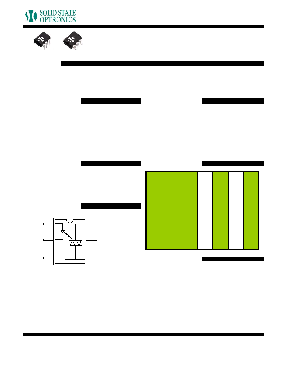
SCHEMATIC DIAGRAM
MAXIMUM RATINGS
APPROVALS
Zero-volt switching
600V blocking voltage
High input-to-output isolation
High reliability
5mA turn-on current
Home appliances
Motor control
Solid state relays
Valve control
Solenoids
Exercise equipment
High Output Isolation
-H
Surface Mount Option
-S
Tape and Reel
-TR
PARAMETER
UNIT
MIN
TYP
MAX
Storage Temperature
�C
-55
125
Operating Temperature
�C
-40
85
Continuous Input Current
mA
40
Transient Input Current
mA
400
Reverse Input Control
Voltage
V
6
Output Power Dissipation
mW
500
1
2
+ Input
- Input
3
6
5
4
+/- AC Outp
ut
Do Not Use
-/+ AC Outp
ut
rev 1.0
Solid State Optronics, Inc.
1.888.377.4776
www.ssousa.com
UL Approved File # E201932

TD3063
Zero-Volt Switching
Triac Driver
PERFORMANCE DATA
0
10
20
30
40
50
590 600 610 620 630 640 650 660
Blocking Voltage (V)
De
v
i
c
e
Co
u
n
t
TD3063
Typical Blocking Voltage Distribution
N = 100, Ambient Temperature = 25�C
0
20
40
60
80
100
120
-40
-20
0
20
40
60
80
Tem perature (C)
Loa
d C
u
r
r
e
nt
(
m
A
)
TD3063
Typical Load Current vs. Temperature
5 V
Threshold
Input Signal
SCR #1 Turns On when
5V threshold is reached.
SCR #1 Turns Off,
SCR #2 Turns On
at Zero Volts.
SCR #2 Turns Off,
SCR #1 Turns On
at Zero Volts.
SCR #1 and Relay Turn
Off at Zero Volts.
5
4
2
6
3
1
Relay Input Signal is
Turned On.
Relay Input Signal is
Turned Off.
This solid state relay has been designed with a driver circuit that controls the operation of two back-to-back silicon controlled rectifiers (SCRs),
each responsible for one half of the AC cycle. If an AC signal is examined, the turn on, turn off and zero-volt switching can be seen. Figure 1
shows a typical 60 Hz, 120Vac signal with a corresponding relay input signal:
ZERO-VOLT SWITCHING
Figure 1 shows the sequence of zero-volt switching operation. At Stage 1, an input signal is applied to the relay. The relay will not turn on
until the threshold voltage of 5V is reached. Once this point is reached (Stage 2), SCR #1 (designated as the SCR which controls positive AC
voltage) turns on. However, SCR #1 only conducts for an instant, as the cycle quickly crosses zero. At this point (Stage 3), SCR #1 will turn
off and SCR #2 (negative AC voltage) turns on. Likewise, at the next zero cross (Stage 4), SCR #2 will turn off and SCR #1 conducts again.
Even though the input signal is terminated at Stage 5, the relay will continue to conduct (typical SCR behavior) until Stage 6, when SCR #1
crosses zero and ceases to conduct. Please note that turn on can likewise begin on the negative phase of the AC cycle with a -5V threshold,
though only the positive phase is shown here.
rev 1.0
Solid State Optronics, Inc.
1.888.377.4776
www.ssousa.com

TD30
63
Zero-Volt Switching
Triac Driver
MECHANICAL DIMENSIONS
6 PIN DUAL IN-LINE PACKAGE
6 PIN SURFACE MOUNT DEVICE
rev 1.0
Solid State Optronics, Inc.
1.888.377.4776
www.ssousa.com
MECHANICAL DIMENSIONS
6 PIN DUAL IN-LINE PACKAGE
6 PIN SURFACE MOUNT DEVICE
Meeting VDE Requirements (Clearance and Creepage) -V
TOLERANCE :+ 0.25mm
Unit
(mm)
