
©2001 Silicon Storage Technology, Inc.
S71167-05-000
9/01
391
1
The SST logo and SuperFlash are registered trademarks of Silicon Storage Technology, Inc.
ATA-Disk Chip is a trademark of Silicon Storage Technology, Inc.
These specifications are subject to change without notice.
Data Sheet
FEATURES:
∑
ATA/IDE standard interface
≠ 512 Bytes per sector
≠ ATA command set compatible
≠ Support Data Transfer Speed up to PIO Mode-4
∑
8, 16, 24, 32, 48, 64, 96, 128, and 192 MByte
capacities
∑
600 mil 32-pin DIP package
∑
Single Voltage Read and Write Operation
≠ 5.0V-only for SST58SDxxx
≠ 3.3V-only for SST58LDxxx
∑
Supports 5.0-Volt or 3.3-Volt Read and Write
≠ 4.5-5.5V or 3.135-3.465V for Commercial
∑
Low Power Consumption
≠ Active mode: 35 mA/55 mA (3.3V/5.0V)(typical)
≠ Sleep mode: 100 µA/150 µA (3.3V/5.0V)(typical)
∑
Extended Data Protection and Security
≠ WP# pin for Data Protection
≠ Factory-Programmed, 20-Byte Unique ID number
∑
Sustained Write Performance
≠ Up to 1.4 MB/sec (host to flash)
∑
Controller Overhead Command to DRQ
≠ Less than 0.5 ms
∑
Zero Power Data Retention
≠ Batteries not required for data storage
∑
Start Up Time
≠ Sleep to read: 200 ns (typical)
≠ Sleep to write: 200 ns (typical)
≠ Power-on to Ready: 200 ms (typical)
∑
Support for Commercial Temperature Range
≠ 0∞C to +70∞C for Operating Commercial
≠ -50∞C to +100∞C for non-Operating (storage)
∑
Extremely Rugged and Reliable
≠ Built-in ECC support corrects 3 Bytes of error
per 512 Byte sector
∑
Intelligent ATA/IDE Controller
≠ Built-in microcontroller with intelligent firmware
≠ Built-in Embedded Flash File System
∑
Power Management Unit
≠ Immediate disabling of unused circuitry
PRODUCT DESCRIPTION
SST's ATA-Disk Chip (ADC) is a low cost, high perfor-
mance, embedded flash memory data storage system.
This product is well suited for solid state mass storage
applications offering new and expanded functionality while
enabling cost effective designs.
ATA-based solid state mass storage technology is widely
used in such products as portable and desktop computers,
digital cameras, music players, handheld data collection
scanners, cellular phones, PCS phones, PDAs, handy termi-
nals, personal communicators, advanced two-way pagers,
audio recorders, monitoring devices, and set-top boxes.
ADC provides complete IDE Hard Disk Drive functionality
and compatibility. ADC is a perfect solution to consumer
electronic products requiring smaller, but more reliable and
cost effective data storage. The ADC is read and written to
using a single power supply of 5.0V or 3.3V and is available
in 8 to 192 MByte capacities.
The ADC is a solid state disk drive that is designed to
replace conventional IDE hard disk drive and uses stan-
dard ATA/IDE protocol. It has built in microcontroller and file
management firmware that communicates with ATA stan-
dard interfaces; therefore, the ADC does not require addi-
tional or proprietary software such as Flash File System
(FFS) and Memory Technology Driver (MTD) software.
The ADC is designed to work at either 5V or 3.3V. The pin
assignment is designed to match existing IDE signal traces
on the motherboard. It uses standard ATA driver that is part
of all major OS such as Windows 95/98/2000/NT/CE,
MAC, UNIX, etc.
All signals, except WP#, are in compliance with the ATA
specifications. WP# is used to write protect the information
stored on the ADC. The WP# can be either connected to
motherboard write protect control logic or a jumper. When
WP# is low, the ADC is write protected to prohibit any inad-
vertent writes.
Every ADC comes with factory-programmed, 20-Byte long,
unique identification number for extended data protection.
This feature prevents unauthorized duplication by allowing
encryption of customer data.
The ADC is packaged in the 600 mil 32-pin DIP package
for easy and cost effective mounting to the system mother-
board.
ATA-Disk Chip
SST58SD008 / 016 / 024 / 032 / 048 / 064 / 096 / 128 / 192
SST58LD008 / 016 / 024 / 032 / 048 / 064 / 096 / 128 / 192
SST58SD/LDxxxATA-Disk Chip
8MB / 16MB / 24MB / 32MB / 48MB / 64MB / 96MB / 128MB / 192MB

2
Data Sheet
ATA-Disk Chip
SST58SD008 / 016 / 024 / 032 / 048 / 064 / 096 / 128 / 192
SST58LD008 / 016 / 024 / 032 / 048 / 064 / 096 / 128 / 192
©2001 Silicon Storage Technology, Inc.
S71167-05-000
9/01
391
TABLE OF CONTENTS
PRODUCT DESCRIPTION . . . . . . . . . . . . . . . . . . . . . . . . . . . . . . . . . . . . . . . . . . . . . . . . . . . . . . . . . . . . . . . . . . . 1
1.0 GENERAL DESCRIPTION . . . . . . . . . . . . . . . . . . . . . . . . . . . . . . . . . . . . . . . . . . . . . . . . . . . . . . . . . . . . . . . 5
1.1 Performance-optimized ATA Controller . . . . . . . . . . . . . . . . . . . . . . . . . . . . . . . . . . . . . . . . . . . . . . . . . . 5
1.1.1 Microcontroller Unit (MCU). . . . . . . . . . . . . . . . . . . . . . . . . . . . . . . . . . . . . . . . . . . . . . . . . . . . . . . 5
1.1.2 Internal Direct Memory Access (DMA) . . . . . . . . . . . . . . . . . . . . . . . . . . . . . . . . . . . . . . . . . . . . . . 5
1.1.3 Power Management Unit (PMU) . . . . . . . . . . . . . . . . . . . . . . . . . . . . . . . . . . . . . . . . . . . . . . . . . . 5
1.1.4 SRAM Buffer . . . . . . . . . . . . . . . . . . . . . . . . . . . . . . . . . . . . . . . . . . . . . . . . . . . . . . . . . . . . . . . . . 5
1.1.5 Embedded Flash File System . . . . . . . . . . . . . . . . . . . . . . . . . . . . . . . . . . . . . . . . . . . . . . . . . . . . 5
1.1.6 Error Correction Code (ECC) . . . . . . . . . . . . . . . . . . . . . . . . . . . . . . . . . . . . . . . . . . . . . . . . . . . . . 5
1.2 SST's ATA-Disk Chip Product Offering . . . . . . . . . . . . . . . . . . . . . . . . . . . . . . . . . . . . . . . . . . . . . . . . . . 6
2.0 ELECTRICAL INTERFACE . . . . . . . . . . . . . . . . . . . . . . . . . . . . . . . . . . . . . . . . . . . . . . . . . . . . . . . . . . . . . . 6
2.0.1 Pin Assignment and Pin Type . . . . . . . . . . . . . . . . . . . . . . . . . . . . . . . . . . . . . . . . . . . . . . . . . . . . 6
2.1 Electrical Description . . . . . . . . . . . . . . . . . . . . . . . . . . . . . . . . . . . . . . . . . . . . . . . . . . . . . . . . . . . . . . . . 6
2.2 Absolute Maximum Stress Ratings . . . . . . . . . . . . . . . . . . . . . . . . . . . . . . . . . . . . . . . . . . . . . . . . . . . . . 9
2.3 Electrical Specification . . . . . . . . . . . . . . . . . . . . . . . . . . . . . . . . . . . . . . . . . . . . . . . . . . . . . . . . . . . . . . 10
2.3.1 Absolute Maximum Conditions. . . . . . . . . . . . . . . . . . . . . . . . . . . . . . . . . . . . . . . . . . . . . . . . . . . 10
2.3.2 Input Leakage Current . . . . . . . . . . . . . . . . . . . . . . . . . . . . . . . . . . . . . . . . . . . . . . . . . . . . . . . . . 10
2.3.3 Input Characteristics. . . . . . . . . . . . . . . . . . . . . . . . . . . . . . . . . . . . . . . . . . . . . . . . . . . . . . . . . . . 11
2.3.4 Output Drive Type . . . . . . . . . . . . . . . . . . . . . . . . . . . . . . . . . . . . . . . . . . . . . . . . . . . . . . . . . . . . 11
2.3.5 Output Drive Characteristics . . . . . . . . . . . . . . . . . . . . . . . . . . . . . . . . . . . . . . . . . . . . . . . . . . . . 11
2.3.6 I/O Input (Read) Timing Specification . . . . . . . . . . . . . . . . . . . . . . . . . . . . . . . . . . . . . . . . . . . . . 12
2.3.7 I/O Output (Write) Timing Specification . . . . . . . . . . . . . . . . . . . . . . . . . . . . . . . . . . . . . . . . . . . . 13
2.4 I/O Transfer Function . . . . . . . . . . . . . . . . . . . . . . . . . . . . . . . . . . . . . . . . . . . . . . . . . . . . . . . . . . . . . . . 14
2.4.1 I/O Function . . . . . . . . . . . . . . . . . . . . . . . . . . . . . . . . . . . . . . . . . . . . . . . . . . . . . . . . . . . . . . . . . 14
3.0 SOFTWARE INTERFACE . . . . . . . . . . . . . . . . . . . . . . . . . . . . . . . . . . . . . . . . . . . . . . . . . . . . . . . . . . . . . . 15
3.1 ATA-Disk Chip Drive Register Set Definitions and Protocol . . . . . . . . . . . . . . . . . . . . . . . . . . . . . . . . . 15
3.1.1 ATA-Disk Chip Addressing. . . . . . . . . . . . . . . . . . . . . . . . . . . . . . . . . . . . . . . . . . . . . . . . . . . . . . 15
3.1.2 ATA-Disk Chip Registers . . . . . . . . . . . . . . . . . . . . . . . . . . . . . . . . . . . . . . . . . . . . . . . . . . . . . . . 15
3.1.2.1 Data Register . . . . . . . . . . . . . . . . . . . . . . . . . . . . . . . . . . . . . . . . . . . . . . . . . . . . . . . . . 15
3.1.2.2 Error Register (Read Only) . . . . . . . . . . . . . . . . . . . . . . . . . . . . . . . . . . . . . . . . . . . . . . . 15
3.1.2.3 Feature Register (Write Only) . . . . . . . . . . . . . . . . . . . . . . . . . . . . . . . . . . . . . . . . . . . . . 16
3.1.2.4 Sector Count Register . . . . . . . . . . . . . . . . . . . . . . . . . . . . . . . . . . . . . . . . . . . . . . . . . . . 16
3.1.2.5 Sector Number (LBA 7-0) Register . . . . . . . . . . . . . . . . . . . . . . . . . . . . . . . . . . . . . . . . . 16
3.1.2.6 Cylinder Low (LBA 15-8) Register. . . . . . . . . . . . . . . . . . . . . . . . . . . . . . . . . . . . . . . . . . 16
3.1.2.7 Cylinder High (LBA 23-16) Register . . . . . . . . . . . . . . . . . . . . . . . . . . . . . . . . . . . . . . . . 16
3.1.2.8 Drive/Head (LBA 27-24) Register . . . . . . . . . . . . . . . . . . . . . . . . . . . . . . . . . . . . . . . . . . 16
3.1.2.9 Status & Alternate Status Registers (Read Only) . . . . . . . . . . . . . . . . . . . . . . . . . . . . . . 17
3.1.2.10 Device Control Register (Write Only) . . . . . . . . . . . . . . . . . . . . . . . . . . . . . . . . . . . . . . 17
3.1.2.11 Drive Address Register (Read Only) . . . . . . . . . . . . . . . . . . . . . . . . . . . . . . . . . . . . . . . 18
3.1.2.12 Command Register (Write Only) . . . . . . . . . . . . . . . . . . . . . . . . . . . . . . . . . . . . . . . . . . 18

Data Sheet
ATA-Disk Chip
SST58SD008 / 016 / 024 / 032 / 048 / 064 / 096 / 128 / 192
SST58LD008 / 016 / 024 / 032 / 048 / 064 / 096 / 128 / 192
3
©2001 Silicon Storage Technology, Inc.
S71167-05-000
9/01
391
3.2 ATA-Disk Chip Command Description . . . . . . . . . . . . . . . . . . . . . . . . . . . . . . . . . . . . . . . . . . . . . . . . . . 19
3.2.1 ATA-Disk Chip Command Set . . . . . . . . . . . . . . . . . . . . . . . . . . . . . . . . . . . . . . . . . . . . . . . . . . . 19
3.2.1.1 Check Power Mode - 98H or E5H . . . . . . . . . . . . . . . . . . . . . . . . . . . . . . . . . . . . . . . . . . 20
3.2.1.2 Execute Drive Diagnostic - 90H . . . . . . . . . . . . . . . . . . . . . . . . . . . . . . . . . . . . . . . . . . . 20
3.2.1.3 Format Track - 50H . . . . . . . . . . . . . . . . . . . . . . . . . . . . . . . . . . . . . . . . . . . . . . . . . . . . . 21
3.2.1.4 Identify Drive - ECH. . . . . . . . . . . . . . . . . . . . . . . . . . . . . . . . . . . . . . . . . . . . . . . . . . . . . 21
3.2.1.4.1 General Configuration. . . . . . . . . . . . . . . . . . . . . . . . . . . . . . . . . . . . . . . . . . . . 23
3.2.1.4.2 Default Number of Cylinders. . . . . . . . . . . . . . . . . . . . . . . . . . . . . . . . . . . . . . . 23
3.2.1.4.3 Default Number of Heads . . . . . . . . . . . . . . . . . . . . . . . . . . . . . . . . . . . . . . . . . 23
3.2.1.4.4 Default Number of Sectors per Track . . . . . . . . . . . . . . . . . . . . . . . . . . . . . . . . 23
3.2.1.4.5 Number of Sectors . . . . . . . . . . . . . . . . . . . . . . . . . . . . . . . . . . . . . . . . . . . . . . 23
3.2.1.4.6 Memory Serial Number. . . . . . . . . . . . . . . . . . . . . . . . . . . . . . . . . . . . . . . . . . . 23
3.2.1.4.7 Buffer Type . . . . . . . . . . . . . . . . . . . . . . . . . . . . . . . . . . . . . . . . . . . . . . . . . . . . 23
3.2.1.4.8 Buffer Size . . . . . . . . . . . . . . . . . . . . . . . . . . . . . . . . . . . . . . . . . . . . . . . . . . . . 23
3.2.1.4.9 ECC Count . . . . . . . . . . . . . . . . . . . . . . . . . . . . . . . . . . . . . . . . . . . . . . . . . . . . 23
3.2.1.4.10 Firmware Revision . . . . . . . . . . . . . . . . . . . . . . . . . . . . . . . . . . . . . . . . . . . . . 23
3.2.1.4.11 Model Number . . . . . . . . . . . . . . . . . . . . . . . . . . . . . . . . . . . . . . . . . . . . . . . . 23
3.2.1.4.12 Read/Write Multiple Sector Count . . . . . . . . . . . . . . . . . . . . . . . . . . . . . . . . . 23
3.2.1.4.13 Capabilities . . . . . . . . . . . . . . . . . . . . . . . . . . . . . . . . . . . . . . . . . . . . . . . . . . . 23
3.2.1.4.14 PIO Data Transfer Cycle Timing Mode. . . . . . . . . . . . . . . . . . . . . . . . . . . . . . 24
3.2.1.4.15 Translation Parameters Valid . . . . . . . . . . . . . . . . . . . . . . . . . . . . . . . . . . . . . 24
3.2.1.4.16 Current Number of Cylinders, Heads, Sectors/Track . . . . . . . . . . . . . . . . . . . 24
3.2.1.4.17 Current Capacity. . . . . . . . . . . . . . . . . . . . . . . . . . . . . . . . . . . . . . . . . . . . . . . 24
3.2.1.4.18 Multiple Sector Setting . . . . . . . . . . . . . . . . . . . . . . . . . . . . . . . . . . . . . . . . . . 24
3.2.1.4.19 Total Sectors Addressable in LBA Mode . . . . . . . . . . . . . . . . . . . . . . . . . . . . 24
3.2.1.4.20 Advanced PIO Data Transfer Mode . . . . . . . . . . . . . . . . . . . . . . . . . . . . . . . . 24
3.2.1.4.21 Minimum PIO Transfer Cycle Time Without Flow Control . . . . . . . . . . . . . . . 24
3.2.1.4.22 Minimum PIO Transfer Cycle Time With IORDY . . . . . . . . . . . . . . . . . . . . . . 24
3.2.1.5 Idle - 97H or E3H. . . . . . . . . . . . . . . . . . . . . . . . . . . . . . . . . . . . . . . . . . . . . . . . . . . . . . . 24
3.2.1.6 Idle Immediate - 95H or E1H. . . . . . . . . . . . . . . . . . . . . . . . . . . . . . . . . . . . . . . . . . . . . . 25
3.2.1.7 Initialize Drive Parameters - 91H. . . . . . . . . . . . . . . . . . . . . . . . . . . . . . . . . . . . . . . . . . . 25
3.2.1.8 Read Buffer - E4H . . . . . . . . . . . . . . . . . . . . . . . . . . . . . . . . . . . . . . . . . . . . . . . . . . . . . . 25
3.2.1.9 Read Multiple - C4H . . . . . . . . . . . . . . . . . . . . . . . . . . . . . . . . . . . . . . . . . . . . . . . . . . . . 26
3.2.1.10 Read Long Sector - 22H or 23H . . . . . . . . . . . . . . . . . . . . . . . . . . . . . . . . . . . . . . . . . . 27
3.2.1.11 Read Sectors - 20H or 21H . . . . . . . . . . . . . . . . . . . . . . . . . . . . . . . . . . . . . . . . . . . . . . 27
3.2.1.12 Read Verify Sector(s) - 40H or 41H . . . . . . . . . . . . . . . . . . . . . . . . . . . . . . . . . . . . . . . 28
3.2.1.13 Recalibrate - 1XH . . . . . . . . . . . . . . . . . . . . . . . . . . . . . . . . . . . . . . . . . . . . . . . . . . . . . 28
3.2.1.14 Seek - 7XH . . . . . . . . . . . . . . . . . . . . . . . . . . . . . . . . . . . . . . . . . . . . . . . . . . . . . . . . . . 28
3.2.1.15 Set Features - EFH . . . . . . . . . . . . . . . . . . . . . . . . . . . . . . . . . . . . . . . . . . . . . . . . . . . . 29
3.2.1.16 Set Multiple Mode - C6H . . . . . . . . . . . . . . . . . . . . . . . . . . . . . . . . . . . . . . . . . . . . . . . . 30
3.2.1.17 Set Sleep Mode - 99H or E6H. . . . . . . . . . . . . . . . . . . . . . . . . . . . . . . . . . . . . . . . . . . . 30
3.2.1.18 Standby - 96H or E2H . . . . . . . . . . . . . . . . . . . . . . . . . . . . . . . . . . . . . . . . . . . . . . . . . . 31
3.2.1.19 Standby Immediate - 94H or E0H . . . . . . . . . . . . . . . . . . . . . . . . . . . . . . . . . . . . . . . . . 31
3.2.1.20 Write Buffer - E8H . . . . . . . . . . . . . . . . . . . . . . . . . . . . . . . . . . . . . . . . . . . . . . . . . . . . . 31
3.2.1.21 Write Long Sector - 32H or 33H . . . . . . . . . . . . . . . . . . . . . . . . . . . . . . . . . . . . . . . . . . 32
3.2.1.22 Write Multiple Command - C5H. . . . . . . . . . . . . . . . . . . . . . . . . . . . . . . . . . . . . . . . . . . 32
3.2.1.23 Write Sector(s) - 30H or 31H. . . . . . . . . . . . . . . . . . . . . . . . . . . . . . . . . . . . . . . . . . . . . 33
3.2.1.24 Write Verify - 3CH . . . . . . . . . . . . . . . . . . . . . . . . . . . . . . . . . . . . . . . . . . . . . . . . . . . . . 33
3.2.2 Error Posting . . . . . . . . . . . . . . . . . . . . . . . . . . . . . . . . . . . . . . . . . . . . . . . . . . . . . . . . . . . . . . . . 34

4
Data Sheet
ATA-Disk Chip
SST58SD008 / 016 / 024 / 032 / 048 / 064 / 096 / 128 / 192
SST58LD008 / 016 / 024 / 032 / 048 / 064 / 096 / 128 / 192
©2001 Silicon Storage Technology, Inc.
S71167-05-000
9/01
391
4.0 APPENDIX . . . . . . . . . . . . . . . . . . . . . . . . . . . . . . . . . . . . . . . . . . . . . . . . . . . . . . . . . . . . . . . . . . . . . . . . . . 35
4.1 Differences between ATA-Disk Chip and ATA/ATAPI-5 Specifications . . . . . . . . . . . . . . . . . . . . . . . . . 35
4.1.1 Electrical Differences . . . . . . . . . . . . . . . . . . . . . . . . . . . . . . . . . . . . . . . . . . . . . . . . . . . . . . . . . . 35
4.1.1.1 TTL Compatibility . . . . . . . . . . . . . . . . . . . . . . . . . . . . . . . . . . . . . . . . . . . . . . . . . . . . . . 35
4.1.1.2 Pull Up Resistor Input Leakage Current . . . . . . . . . . . . . . . . . . . . . . . . . . . . . . . . . . . . . 35
4.1.2 Functional Differences . . . . . . . . . . . . . . . . . . . . . . . . . . . . . . . . . . . . . . . . . . . . . . . . . . . . . . . . . 35
4.1.2.1 Idle Timer . . . . . . . . . . . . . . . . . . . . . . . . . . . . . . . . . . . . . . . . . . . . . . . . . . . . . . . . . . . . 35
4.1.2.2 Recovery from Sleep Mode. . . . . . . . . . . . . . . . . . . . . . . . . . . . . . . . . . . . . . . . . . . . . . . 35
5.0 PHYSICAL DIMENSIONS . . . . . . . . . . . . . . . . . . . . . . . . . . . . . . . . . . . . . . . . . . . . . . . . . . . . . . . . . . . . . . 36
6.0 PRODUCT ORDERING INFORMATION . . . . . . . . . . . . . . . . . . . . . . . . . . . . . . . . . . . . . . . . . . . . . . . . . . . 37
6.1 Valid Combinations . . . . . . . . . . . . . . . . . . . . . . . . . . . . . . . . . . . . . . . . . . . . . . . . . . . . . . . . . . . . . . . . 38
7.0 LIMITED WARRANTY . . . . . . . . . . . . . . . . . . . . . . . . . . . . . . . . . . . . . . . . . . . . . . . . . . . . . . . . . . . . . . . . . 39
7.1 Life Support Policy . . . . . . . . . . . . . . . . . . . . . . . . . . . . . . . . . . . . . . . . . . . . . . . . . . . . . . . . . . . . . . . . . 39
7.2 Patent Protection . . . . . . . . . . . . . . . . . . . . . . . . . . . . . . . . . . . . . . . . . . . . . . . . . . . . . . . . . . . . . . . . . . 39
Data Sheet
ATA-Disk Chip
SST58SD008 / 016 / 024 / 032 / 048 / 064 / 096 / 128 / 192
SST58LD008 / 016 / 024 / 032 / 048 / 064 / 096 / 128 / 192
5
©2001 Silicon Storage Technology, Inc.
S71167-05-000
9/01
391
1.0 GENERAL DESCRIPTION
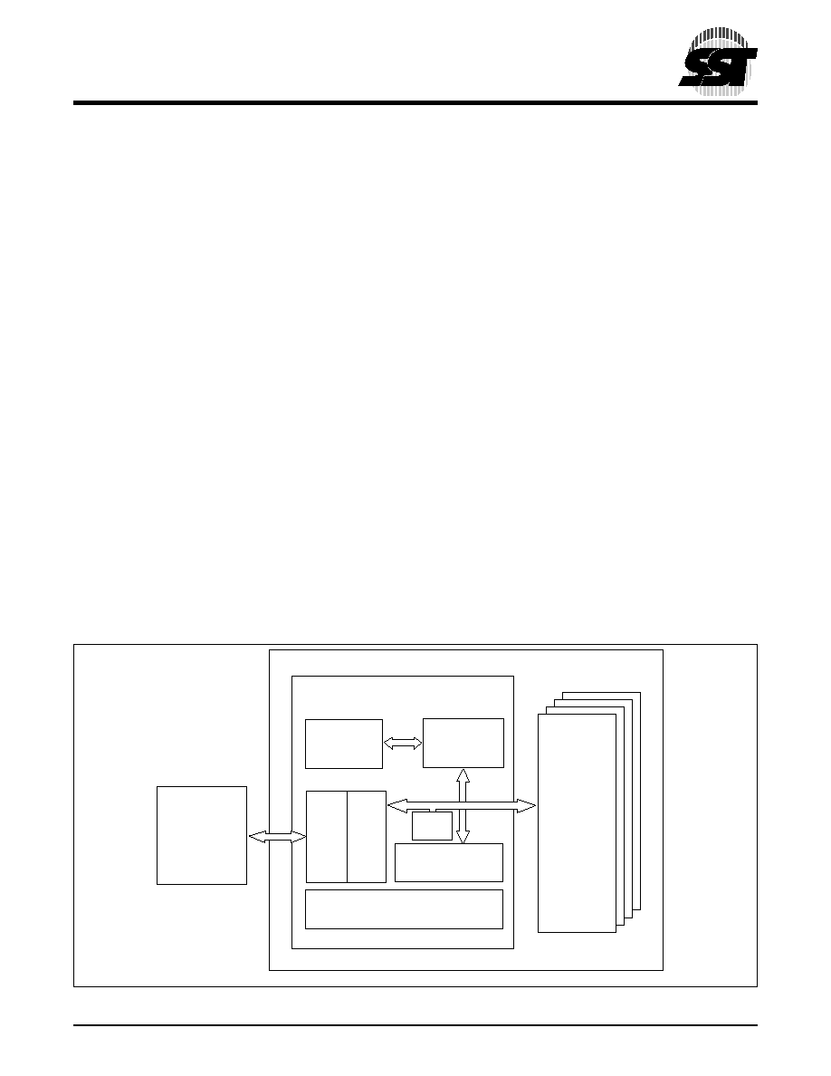
The SST's ATA-Disk Chip (ADC) contains a controller,
embedded firmware and Flash Media in a 32-pin DIP pack-
age. Refer to Figure 1-1 for SST's ADC block diagram. The
controller interfaces with the host system allowing data to
be written to and read from the Flash Media.
1.1 Performance-optimized ATA Controller
The heart of the ADC is the ATA controller which translates
standard ATA signals into Flash Media data and controls.
SST's ADC contains a proprietary ATA controller that was
specifically designed to attain high data throughput from
host to Flash. The following components contribute to the
ATA controller's operation.
1.1.1 Microcontroller Unit (MCU)
The MCU translates ATA commands into data and control
signals required for flash memory operation.
1.1.2 Internal Direct Memory Access (DMA)
The ATA controller inside ADC uses DMA allowing instant
data transfer from buffer to memory. This implementation
eliminates microcontroller overhead associated with tradi-
tional, firmware based, memory control, increasing data
transfer rate.
1.1.3 Power Management Unit (PMU)
Power Management Unit controls the power consumption
of the ADC. The PMU dramatically extends product battery
life by putting the part of the circuitry that is not in operation
into sleep mode.
1.1.4 SRAM Buffer
A key contributor to the ATA controller performance is an
SRAM buffer. The buffer optimizes host's data writes to
Flash Media.
1.1.5 Embedded Flash File System
Embedded Flash File System is an integral part of the
SST's ATA controller. It contains MCU Firmware that per-
forms the following tasks:
1. Translates host side signals into Flash Media
Writes and Reads.
2. Provides Flash Media wear leveling to spread the
Flash writes across all the memory address space
to increase the longevity of Flash Media.
3. Keeps track of data file structures.
1.1.6 Error Correction Code (ECC)
The ATA Controller contains ECC algorithm that corrects
3 Bytes of error per 512 Byte sector.
FIGURE
1-1: SST ATA-D
ISK
C
HIP
B
LOCK
D
IAGRAM
391 ILL1-1.5
HOST
ATA/IDE
BUS
ATA Controller
Flash
Media
Embedded
Flash
File System
MCU
ECC
Internal
DMA
SRAM Buffer
PMU