Product Guide
Product Guide
Product Guide
s
Electro-Optical Characteristics
Part No.
Water
Clear
TYP. I
F
Wavelength
Spectral Line
Half Width
Forward
Voltage
V
F
TYP. MAX. I
F
Reverse
Current
IR
MAX. V
R
Viewing
Angle
(2
1/2)
Red
Orange
Yellow
Pure Green
Green
Bluish-Green
Blue
70
70
70
10
120
120
50
35
35
35
5
60
60
25
20
20
20
20
20
20
20
645
609
588
555
518
502
468
632
605
587
557
525
505
470
15
15
15
30
30
30
30
20
20
20
20
20
20
20
2.0
2.0
2.0
2.1
3.5
3.5
3.5
2.5
2.5
2.5
2.5
4.0
4.0
4.0
20
20
20
20
20
20
20
100
100
100
100
100
100
100
5
5
5
4
5
5
5
AllnGap
AllnGap
AllnGap
GaP
InGaN/SIC
InGaN/SIC
InGaN/SIC
FR1104B
FA1104B
FY1104B
BG1104B
DG1104B
DC1104B
DB1104B
Units
mcd
mA
nm
mA
mA
µA
V
Deg.
V
MIN.
TYP.
Peak
p
TYP.
Dominant
d
TYP.
I
F
Luminous
Intensity
IV
Lens
Color
Emitted
Color
120∞
s
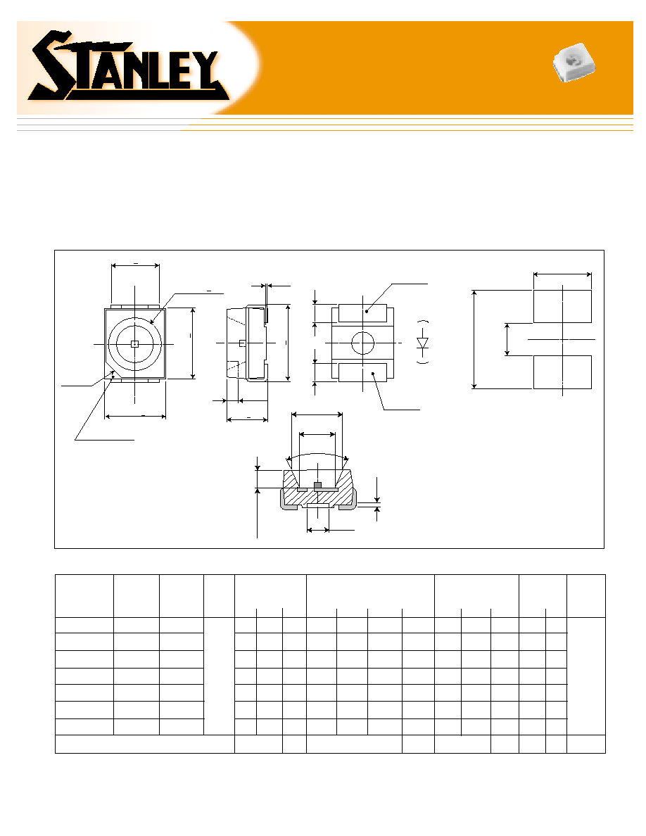
Outline Dimensions
s
Features
∑ Wide viewing angle, top view SMT LED
∑ Extended operating temperature range
∑
from -40 to +100∞C
∑ PLCC-2 package
∑ Available on EIAJ standard ETX-7001 reels
s
Applications
∑ Indicator for automotive instrument panel,
∑
back-lighting for radio or A/C control panels
2.2 +0.1
2.8+0.2
1.9+0.2
(0.5)
(Cathode)
(Anode)
0.1
(C0.8)
(Cathode Mark)
2.4 +0.1
3.2+0.2
3.5+0.2
0.8
0.8
1.65
45∞
1.0
2.4
0.85
0.2
(2.6)
(1.5)
(4.5)
s Recommended Solder Pad
1104B Series Bath Tub (PLCC-2) Type SMT LED
1104B Series Bath Tub (PLCC-2) Type SMT LED
Material
Unit: mm
(Ta=25∞C)
Green
DG
80
20
50
5
s
Absolute Maximum Ratings
Power Dissipation
Forward Current
Peak Forward Current
Reverse Voltage
Operating Temperature
Storage Temperature
Derating
Symbol
Pd
I
F
I
FM
V
R
Topr
Tstg
I
F
Red
FR
81
30
100
5
Orange
FA
81
30
100
5
FY
81
30
100
5
DC
80
20
50
5
Blue
DB
80
20
50
5
Pure
Green
BG
125
50
125
4
mW
mA
mA
V
∞C
∞C
mA/∞C
∑ Ta=25∞C
∑
I
FM
applies for the pulse width 1msec. and duty cycle 1/20.
0.75 (60∞C ~ 100∞C)
0.5 (60∞C ~ 100∞C)
1.0
(50∞C ~ 100∞C)
Yellow
Bluish-
Green
Units
Item
-40 to +100
-40 to +110
s
Precautions
Please follow these handling precautions to prevent damage to the chip and
ensure its reliability.
1. Soldering conditions:
∑ Soldering iron: Temperature at tip of iron: 280∞C max. (30W max.)
Soldering time: 3 sec. max.
∑ Dip soldering: Preheating: 100∞C max. (resin surface temp.)
60 sec. max. Bath temperature: 260∞C max. Dipping Time: 5 sec. max.
∑ Reflow Soldering:
2. Cleaning:
∑ If cleaning is required, use the following solutions for less than 1 minute,
at less than 40∞C.
∑ Appropriate chemicals: Ethyl alcohol and isopropyl alcohol.
∑ Effect of ultrasonic cleaning on the LED resin body differs depending on such
factors as the oscillator output, size of PCB and LED mounting method. The
use of ultrasonic cleaning is strongly recommended after confirming there
is no problem.
Product specifications subject to change without notice. PG1104B-0301
s
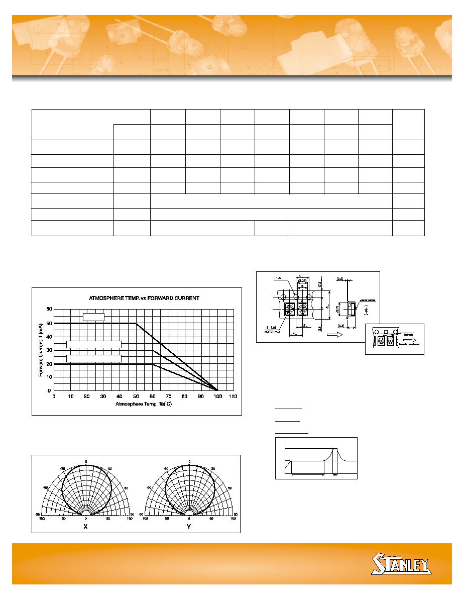
Taping Specifications
s
Operation Current Derating Chart
BG
FR, FA, FY
DG, DC, DB, EB
s
Spatial Distribution
Stanley Electric Sales of America, Inc.
2660 Barranca Parkway, Irvine, CA 92606
∑
∑ Tel: 800-LED-LCD1 (533-5231)
∑
∑ Fax: 949-222-0555
Website: www.stanley-electric.com
Operation Heating
Pre-heating
LED Surf
ace
T
emper
ature
Temperature
rise: 5∞C/sec.
Cooling:
--5∞C/sec.
60 to 120 sec.
5 sec. max
0
120
150
240
∞C
~
+0.1
0
+0.1
+0.05
+0.05
+0.1
+0.
1
+0.2
Direction to pull
Quantity on tape:
2000 pieces
per reel
(Ta=25∞C)