Product Guide
Product Guide
Product Guide
s
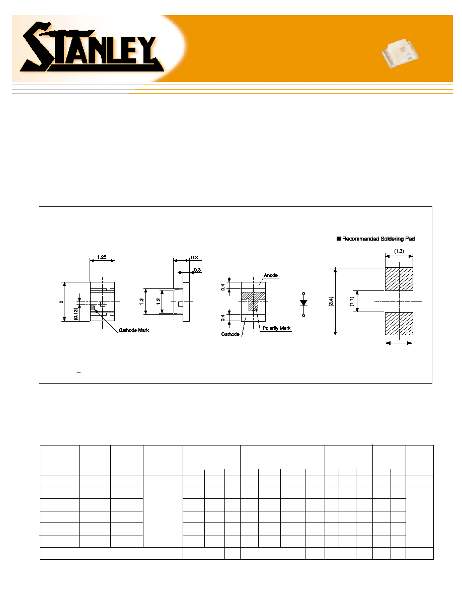
Outline Dimensions
s
Features
∑ Meets industry standards for 2012 (0806) footprint
∑
2.0mm (L) x 1.25mm (W) x 0.8mm (H)
∑ 1112H is 50% thinner than the W series.
s
Applications
∑ Membrane switch panels
∑ Backlighting
∑ Cellular telephones
PCB Warpage direction
1112H Series Thin Type SMT LED
1112H Series Thin Type SMT LED
Unit: mm
Tolerances + 0.1
s
Electro-Optical Characteristics
Milky
White
Wavelength
Spectral Line
Half Width
Forward
Voltage
V
F
TYP
MAX.
I
F
Reverse
Current
IR
MAX. V
R
Viewing
Angle
(2
1/2)
11.7
3.7
3.7
11.7
6.4
2.7
7.0
2.2
2.2
7.0
3.8
1.6
20
20
20
20
20
20
660
605
580
570
560
555
647
606
590
572
567
558
30
30
30
30
30
30
20
20
20
20
20
20
1.7
2.2
2.2
2.1
2.1
2.1
2.3
2.8
2.8
2.8
2.8
2.8
20
20
20
20
20
20
100
100
100
100
100
100
4
4
4
4
4
4
GaAIAs
GaAsP
GaAsP
GaP
GaP
GaP
Red
Orange
Yellow
Yellow-Green
Green
Pure Green
BR1112H
AA1112H
AY1112H
PY1112H
PG1112H
BG1112H
mcd
mA
nm
mA
mA
µA
V
Deg.
V
MIN.
TYP.
I
F
TYP.
Peak
p
TYP.
Dominant
d
TYP.
I
F
Luminous
Intensity
IV
Lens
Color
Emitted
Color
160∞
150∞
Material
Type No.
(Ta=25∞C)
Units
s
Precautions
Please follow these handling precautions to prevent damage to the chip and
ensure its reliability.
1. Soldering conditions:
∑ Soldering iron: Temperature at tip of iron: 280∞C max. (30W max.)
Soldering time: 3 sec. max.
∑ Dip soldering: Preheating: 120 ~ 150∞C max. (resin surface temp.)
60 ~ 120 sec. max. Bath temperature: 260∞C max. Dipping Time: 5 sec. max.
∑ Reflow Soldering:
2. Cleaning:
∑ If cleaning is required, use the following solutions for less than 1 minute,
at less than 40∞C.
∑ Appropriate chemicals: Ethyl alcohol and isopropyl alcohol.
∑ Effect of ultrasonic cleaning on the LED resin body differs depending on such
factors as the oscillator output, size of PCB and LED mounting method. The
use of ultrasonic cleaning should be enforced at proper output after confirming
there is no problem.
Product specifications subject to change without notice. PG1112H-0301
s
Taping Specifications
s
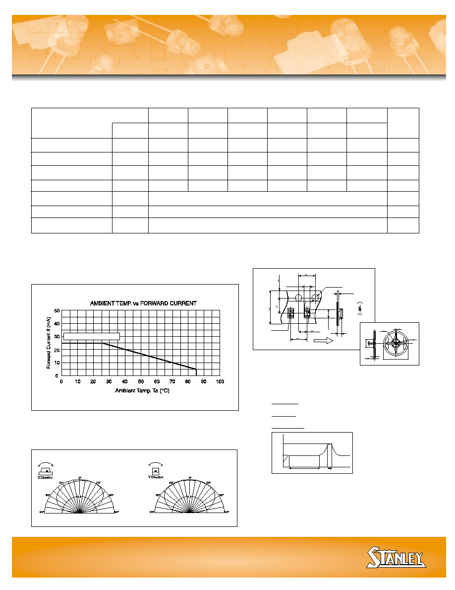
Operation Current Derating Chart (DC)
BR, AA, AY, PY, PG, BG
s
Spatial Distribution
Stanley Electric Sales of America, Inc.
2660 Barranca Parkway, Irvine, CA 92606
∑
∑ Tel: 800-LED-LCD1 (533-5231)
∑
∑ Fax: 949-222-0555
Website: www.stanley-electric.com
Operation Heating
Pre-heating
LED Surf
ace
T
emper
ature
Temperature
rise: 5∞C/sec.
Cooling:
--5∞C/sec.
60 to 120 sec.
5 sec. max
0
120
150
240
∞C
~
(0.2)
(2.25)
( 0.5)
Center
Hole
(1.45)
(1)
4+0.1
1.5
+0.1
0
8+0
.
2
2+0.05
4+0.1
3.5
+0.05
1.75
+
0.1
Direction to pull
Quantity on tape:
4000 pieces
per reel
(Ta=25∞C)
s
Absolute Maximum Ratings
Power Dissipation
Forward Current
Peak Forward Current
Reverse Voltage
Operating Temperature
Storage Temperature
Derating*
Symbol
Pd
I
F
I
FM
V
R
Topr
Tstg
I
F
mW
mA
mA
V
∞C
∞C
mA/∞C
* Ta=25∞C,
I
FM
applies for the pulse width 1msec. and duty cycle 1/20.
0.36 (DC) 0.86 (Pulse)
Units
Item
-30 to +85
-40 to +100
Red
BR
57.5
25
60
4
Orange
AA
70
25
60
4
Yellow
AY
70
25
60
4
Green
PG
70
25
60
4
21+0.8
9+0.3
11.4+1
13+0.2
180
+0
3
60
+
1
-0
13+0.2
2+0.5
Yellow
Green
PY
70
25
60
4
Pure
Green
BG
70
25
60
4