1
s
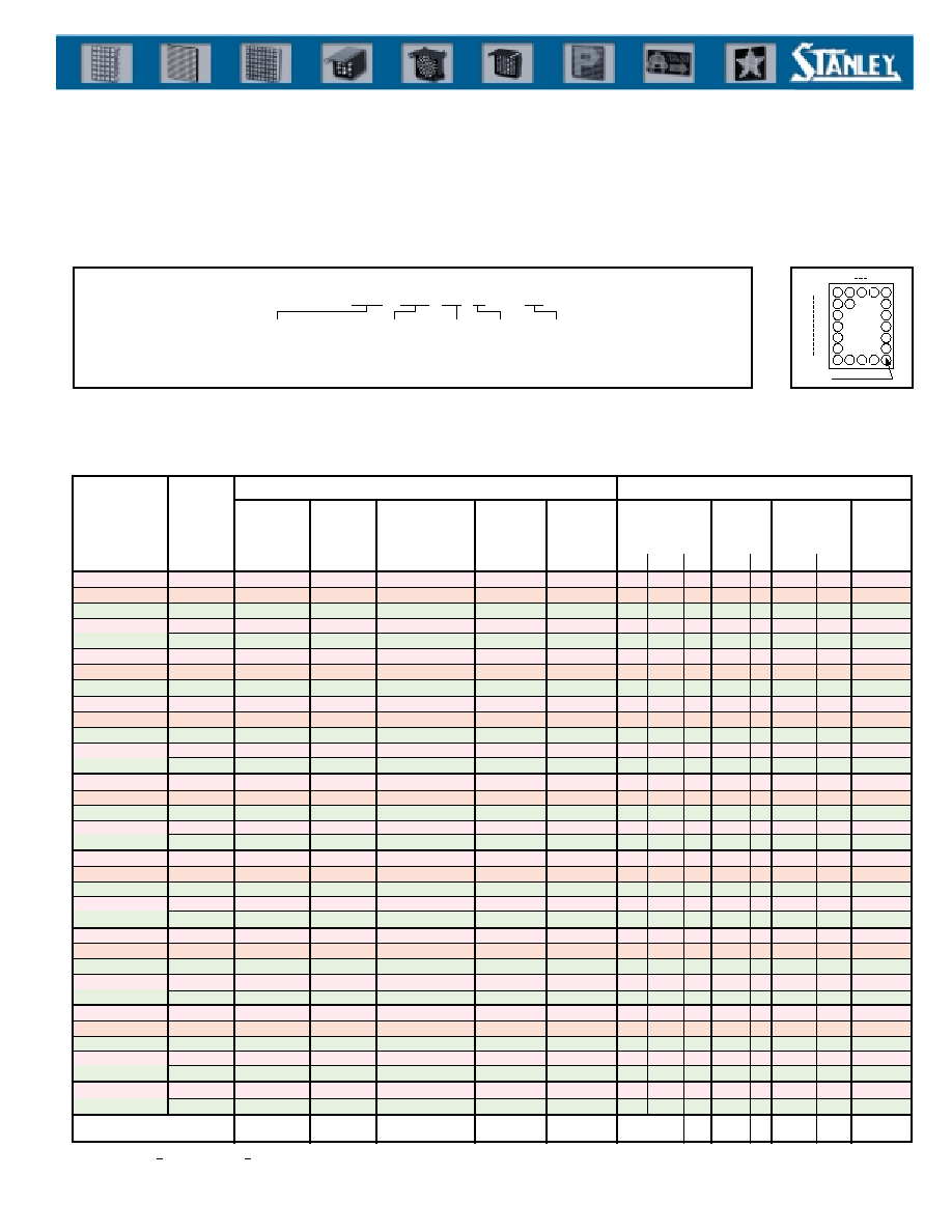
Description of Part Number
MD 06 57 C 2 - R
Outer Dimensions
No. of Dots
Type
Emitted Color
06, 07 : 17~20mm
12 : 32mm
20 : 53mm
15 : 40mm
57 : 5 X 7
08 : 8 X 8
16 : 16 X 16
C : Chip
M : Mold
R : Red
A : Orange
RG : Red/Green
G : Green
MK : Mold, Square
25 : 64mm
37 : 96mm
Additional
Number
s
Column/Row
COL. 1
COL. 5
ROW 1
ROW 7
COL. 5 ROW 7
LED DOT MATRIX DISPLAY
The MD series of Stanley dot matrix displays can handle virtually any display application including numbers, letters,
special characters and graphics. To best serve our customer's needs, configurations of 5 x 7, 8 x 8, and 16 X 16 dots are
available in both single color and bicolor.
(Ta=25�C)
s
Characteristics by Color (Each Chip) -
Ratings and specifications are for each segment
*1 I
FM
condition: tw
0.2msec. and duty
1/5 where the lighting ratio is 50% max.
*2 Value applies when a single color is lit. If the two colors are lit, total values shall be within specified ratings.
Emitted
Color
Power
Dissipation
Pd
Forward
Current
I
F
Peak Forward
Current
I
FM
Operating
Temp.
Topr
Storage
Temp.
Tstg
Absolute Maximum Ratings
Forward
Voltage
V
F
TYP. MAX. I
F
Reverse
Current
I
F
MAX. V
R
Peak
Wavelength
p
TYP.
I
F
Derating
I
FM
Electro-Optical Characteristics
Orange
Green
Red
Green
MD0657C2-R
MD0657C2-A
MD0657C2-G
MD0657C2-RG
Part No.
mW
�C
V
mA
mA
mA
�
A
V
nm
mA
mA/�C
Unit
Red
36
36
30
30
30
15
15
15
15
15
80
80
60
60
80
2.0
2.0
1.7
2.0
1.7
2.4
2.4
2.0
2.4
2.0
10
10
10
10
10
100
100
100
100
100
4
4
4
4
4
605
570
660
570
660
0.89
0.89
0.89
0.89
0.89
10
10
10
10
10
-20 ~ +70
-20 ~ +70
-20 ~ +70
-20 ~ +70
-20 ~ +70
�C
-20 ~ +85
-20 ~ +85
-20 ~ +85
-20 ~ +85
-20 ~ +85
Orange
Green
MD0657M-R
MD0657M-A
MD0657M-G
Red
36
36
30
15
15
15
60
60
60
2.0
2.0
1.7
2.4
2.4
2.0
10
10
10
100
100
100
4
4
4
605
570
660
0.89
0.89
0.89
10
10
10
-20 ~ +70
-20 ~ +70
-20 ~ +70
-20 ~ +85
-20 ~ +85
-20 ~ +85
*1
*2
*2
*2
*2
*2
*2
Red
Green
MD0708C-RG
10
10
�
�
65
65
1.7
2.1
2.0
2.2
20
20
20
20
6.5
6.5
660
570
1.16
1.16
20
20
-20 ~ +60
-20 ~ +60
-20 ~ +80
-20 ~ +80
*2
*2
*2
*2
Orange
Green
Red
Green
Red
Orange
Green
MD0657MK-R
MD0657MK-A
MD0657MK-G
MD0708C-R
MD0708C-A
MD0708C-G
MD0657MK-RG
Red
36
36
30
30
10
10
10
30
15
15
15
15
�
�
�
15
60
60
60
60
80
65
65
60
2.0
2.0
1.7
2.0
1.7
2.2
2.1
1.7
2.4
2.4
2.0
2.4
2.0
2.5
2.5
2.0
10
10
10
10
20
20
20
10
100
100
100
100
20
20
20
100
4
4
4
4
6.5
6.5
6.5
4
605
570
660
570
660
605
570
660
0.89
0.89
0.89
0.89
1.45
1.16
1.16
0.89
10
10
10
10
20
20
20
10
-20 ~ +70
-20 ~ +70
-20 ~ +70
-20 ~ +70
-20 ~ +60
-20 ~ +60
-20 ~ +60
-20 ~ +70
-20 ~ +85
-20 ~ +85
-20 ~ +85
-20 ~ +85
-20 ~ +80
-20 ~ +80
-20 ~ +80
-20 ~ +85
*2
*2
*2
*2
*2
*2
Red
Green
MD2516C
-KRG
-ARG
22
22
�
�
70
70
1.7
2.1
2.0
2.5
20
20
20
20
6.5
6.5
660
570
0.5
0.5
20
20
-20 ~ +70
-20 ~ +70
-30 ~ +80
-30 ~ +80
*2
*2
*2
*2
Orange
Green
Red
Green
Red
Orange
Green
MD1516C2-R
MD1516C2-A
MD1516C2-G
MD2516C-R
MD2516C-A
MD2516C-G
MD1516C2-RG
Red
10
10
10
10
22
22
22
10
�
�
�
�
�
�
�
�
65
65
80
65
70
70
70
80
2.2
2.1
1.7
2.1
1.7
2.2
2.1
1.7
2.5
2.5
2.0
2.5
2.0
2.5
2.5
2.0
20
20
20
20
20
20
20
20
20
20
20
20
20
20
20
20
6.5
6.5
6.5
6.5
6.5
6.5
6.5
6.5
605
570
660
570
660
605
570
660
1.16
1.16
1.45
1.16
0.5
0.5
0.5
1.45
20
20
20
20
20
20
20
20
-20 ~ +60
-20 ~ +60
-20 ~ +60
-20 ~ +60
-20 ~ +70
-20 ~ +70
-20 ~ +70
-20 ~ +60
-20 ~ +80
-20 ~ +80
-30 ~ +80
-30 ~ +80
-30 ~ +80
-30 ~ +80
-30 ~ +80
-20 ~ +80
*2
*2
*2
*2
Red
Green
MD1216C-RG
6.25
6.25
�
�
50
40
1.7
2.1
2.0
2.5
20
20
20
20
4
4
660
570
1.3
1.0
20
20
-30 ~ +70
-30 ~ +70
-30 ~ +80
-30 ~ +80
Red
Orange
Green
MD1216C-R
MD1216C-A
MD1216C-G
6.5
6.5
6.5
�
�
�
50
40
40
1.7
2.2
2.1
2.0
2.5
2.5
20
20
20
20
20
20
6.5
6.5
6.5
660
605
570
0.89
0.71
0.71
20
20
20
-20 ~ +60
-20 ~ +60
-20 ~ +60
-20 ~ +80
-20 ~ +80
-20 ~ +80
Red
Green
MD3716M2-RG
11
11
�
�
70
70
1.7
2.1
2.0
2.5
20
20
20
20
6.5
6.5
660
570
0.5
0.5
20
20
-20 ~ +70
-20 ~ +70
-30 ~ +80
-30 ~ +80
*2
*2
*2
*2

2
LED DOT MATRIX DISPLAY
Emitted Color
Display Area
Dot Size
Dot Pitch
Number of
Dots
MD0657C2-
o
MD0657C2-RG
2.0
2.54
5 X 7
1
2
3
Part No.
Shape
mm
mm
mm
dot
Unit
10.16
12.7
35-
2.0
1
6
12
7
P2.54
15.24
17.78
4.6 6.5
2.54
(12.7)
0.45
(7.62)
1MAX.
COL.1
5
ROW
7
1
1
12
1
1
2
11
2
3
3
2
3
10
4
9
4
7
5
4
5
8
6
5
7
6
ROW
PIN NO.
COL.
PIN NO.
10.16
12.7
35-
2.0
1
5
16
20
P2.54
15.24
17.78
4.8 6.5
10.16
0.45
(7.62)
1MAX.
P2.54
11
6
15
9
35-
2
P2.54
R35
1
1
1
6
3
2
16
2
2
9
3
17
3
8
15
4
13
4
11
20
5
14
5
19
18
6
5
7
4
ROW
PIN NO.
COL.
COL.1
COL. 5
ROW
7
COM
R1
G1
G35
PIN
NO.
R
G
1
10.16
14
35
-
2.2
1
6
12
7
P2.54
15.24
20
6
5
�
0.5
2.54
(12.7)
0.45
(7.62)
COL.1
5
ROW
7
1
1
12
1
1
2
11
2
3
3
2
3
10
4
9
4
7
5
4
5
8
6
5
7
6
ROW
PIN NO.
COL.
PIN NO.
s
Outline Dimensions
s
Characteristics by Shape
Single Color R-A-G
12.7 X 17.7
14 X 20
Bi-Color R-G
MD0657MK-
o
MD0657MK-RG
o
2.2
2.54
5 X 7
4
5
Single Color R-A-G
14 X 20
Bi-Color R-G
MD0708C-
o
MD0708C-RG
1.8
2.50
8 X 8
6
7
Single Color R-A-G
20 X 20
Bi-Color R-G
MD1216C-
o
MD1216C-RG
1.6
2.00
16 X 16
8
9
Single Color R-A-G
32 X 32
Bi-Color R-G
MD1516C2-
o
MD1516C2-RG
1.8
2.49
16 X 16
10
11
Single Color R-A-G
40 X 40
Bi-Color R-G
MD2516C-
o
MD2516CKRG, ARG*
3.0
4.00
16 X 16
12
13
Single Color R-A-G
64 X 64
4.8
6.00
16 X 16
96 X 96
Bi-Color R-G
Bi-Color R-G
MD3716M2-RG
* KRG-Cathode Type, ARG-Anode Type Emitted Color: R-Red, A-Orange, G-Green
14
MD0657M-
o
2.2
2.54
5 X 7
Single Color R-A-G
Fig.
Unit: mm
Fig. 1
Fig. 2
Fig. 3
C Type
M Type
MK Type
20
32
64
96
40

3
LED DOT MATRIX DISPLAY
35-
1
2.2
6
5
�
0.5
P2.54
(12.7)
10.16
14
1
6
12
P2.54
15.24
20
7
0.45
(7.62)
1
12
1
1
2
11
2
3
3
2
3
10
4
9
4
7
5
4
5
8
6
5
7
6
ROW
PIN NO.
COL
PIN NO.
COL.1
5
ROW
7
1
.
1
1
1
6
3
2
16
2
2
9
3
17
3
8
12
4
13
4
11
20
5
14
5
19
18
6
5
7
4
ROW
PIN NO.
COL.
PIN
NO.
R
G
2.54
0.45
(7.62)
6 5
�
0.5
P2.54
(10.16)
6.35
10.16
14
1
5
16
P2.54
15.24
20
35-
1
2.2
11
6
14
9
20
R35
COL.1
5
ROW
7
1
COM
R1
G1
G35
64-
1.8
20 MAX.
7xP2.5=17.5
20
MAX.
7xP2.5=17.5
2
0.45
4-
0.8 PIN
3.8
6
(15)
10
7xP2.5=(17.5)
10
15
4-
4 MAX
(CO.8)
COL.1
8
8
1
R1
R64
COL.1
8
ROW
8
1
1
64
ROW
MD0708C-R
MD0708C-A,G
1
1
1
5
2
2
2
6
3
3
3
7
4
4
4
8
5
12
5
16
6
11
6
15
7
10
7
14
ROW
PIN NO.
COL.
8
9
8
13
1
1
1
5
2
2
2
6
3
3
3
7
4
4
4
8
5
12
5
16
6
11
6
15
7
10
7
14
ROW
PIN NO.
COL.
8
9
8
13
8
1
16
9
PIN NO.
PIN NO.
1
(15)
10
5
6
x
P2.5=(15)
10
15
4-
4MAX.
(CO.8)
64-
1.8
20 MAX.
7xP2.5=17.5
20
MAX.
7xP2.5=17.5
2
0.45
4-
0.8 PIN
3.8
6
COL.1
8
8
ROW
1
R1
G1
R64
G64
COM
1
1
15
1
5
2
2
16
2
6
3
3
17
3
7
4
4
18
4
19
5
11
23
5
24
6
10
22
6
14
7
9
21
7
13
ROW
PIN NO.
8
8
20
8
12
PIN
NO.
R
G
COL
7
8
14
15
24
19
20
s
Outline Dimensions
Unit: mm
Fig. 4
Fig. 5
Fig. 6
Fig. 7
CN24
CN25
MD1216C-A,G
MD1216C-R
1
25
1
1
2
26
2
2
3
27
3
3
14
11
14
19
10
15
10
23
6
30
6
6
7
31
7
7
8
32
8
8
ROW
PIN NO.
13
12
13
20
12
13
12
21
11
14
11
22
4
28
4
4
9
16
9
24
5
29
5
5
16
9
16
17
15
10
15
18
COL.
PIN NO.
1
25
1
1
2
26
2
2
3
27
3
3
14
11
14
19
10
15
10
23
6
30
6
6
7
31
7
7
8
32
8
8
ROW
PIN NO.
13
12
13
20
12
13
12
21
11
14
11
22
4
28
4
4
9
16
9
24
5
29
5
5
16
9
16
17
15
10
15
18
COL.
PIN NO.
32 MAX.
15xP2=30
256-
1.6
32
MAX.
15xP2=30
CN17
CN16
CN9
CN1
CN32
CN8
2
6
3.8
4-
1PIN
8
8
8
8
24
7xP2=14
5-
4 MAX.
9
16
8
32
25
24
17
24
(C 0.6)
1
COL. 1
16
A256
G256
A1,G1
ROW
16
1
COL.1
16
R256
R1
ROW
16
1
0.45
32 MAX.
15xP2=30
256-
1.6
32 MAX.
15xP2=30
1
4-
1 PIN
10
24
14xP2=28
5-
4 MAX.
36
24
14
10
14
13
24
48
37
25
1
12
12
13
25
37
48
36
24
2
6
3.8
0.45
COL.1
16
R1
ROW
16
1
G1
1
13
1
48
37
2
23
2
42
41
3
14
3
43
30
4
15
4
29
40
5
16
5
47
39
6
17
6
46
38
7
18
7
45
27
8
24
8
44
28
COL.
PIN NO.
ROW
PIN
NO.
R
G
9
25
9
7
6
10
31
10
5
4
11
32
11
3
21
12
33
12
20
9
13
34
13
8
22
14
35
14
19
11
15
26
15
1
10
16
36
16
2
12
R256
G256
Fig. 8
Fig. 9
40 MAX.
15xP2.49=37.35
40 MAX.
15xP2.49=37.35
256-
1.8
5-
4 MAX.
10
10
30
10 7xP2.5=(17.5)
30
9
10
8
1
24
17
16
32
25
10
10
7.5
7.5
MD1516C2-R
MD1516C2-A,G
COL.1
16
ROW
16
1
25
1
1
2
26
2
2
3
27
3
3
4
28
4
4
5
29
5
5
6
30
6
6
7
31
7
7
8
32
8
8
9
16
9
24
10
15
10
23
11
14
11
22
12
13
12
21
13
12
13
20
14
11
14
19
15
10
15
18
16
9
16
17
ROW
PIN NO.
COL.
COL.1
16
R16
R256
R1
ROW
16
1
25
1
1
2
26
2
2
3
27
3
3
4
28
4
4
5
29
5
5
6
30
6
6
7
31
7
7
8
32
8
8
9
16
9
24
10
15
10
23
11
14
11
22
12
13
12
21
13
12
13
20
14
11
14
19
15
10
15
18
16
9
16
17
ROW
PIN NO.
COL.
PIN NO.
1
4-
1.1 HOLE
A,G1
A,G256
A,G16
3.8
2
0.45
4-
1
6
PIN NO.
40 MAX.
15xP2.49=37.35
40
MAX.
15 X P2.49=37.35
256-
1.8
3.8
2
0.45
4-
1
5-
4 MAX.
17.5
10
10
30
10 7xP2.5=(17.5)
30
17.5
41
48
1
8
9
33
40
16
32
24
25
17
10
6
COL.1
16
COM
G256
R1
ROW
16
R256
COM
G1
1
25
41
1
1
2
26
42
2
2
3
27
43
3
3
4
28
44
4
4
5
29
45
5
5
6
30
46
6
6
7
31
47
7
7
8
32
48
8
8
9
16
40
9
24
10
15
39
10
23
11
14
38
11
22
12
13
37
12
21
13
12
36
13
20
14
11
35
14
19
15
10
34
15
18
16
9
33
16
17
ROW
PIN
NO.
COL.
PIN NO.
R
G
1
Fig. 10
Fig. 11
Unit: mm

4
LED DOT MATRIX DISPLAY
4.7K
Vcc
s
Recommended Operating Conditions
1. Recommended drive conditions: 1/16 duty
LED on time: 1 msec.
Lighting frequency: 62.5 Hz
{Since the recommended value of the peak forward
current (I
FM
) may vary depending on product con-
figurations or operating conditions, please consult us
first. When the lighting frequency goes below 50 Hz,
a flicker may appear on the display screen.}
Buffer circuit detailed diagram
2. Recommended drive circuit:
Block Diagram
FLM
CLOCK
DST
EN G
EN R
G DATA
R DATA
FLM
CLOCK
DST
EN G
EN R
G DATA
R DATA
Buff
er
Luminance adjustment
SW (Red)
Segment driver
Green
Common
dr
iv
er
TRA
Segment driver
Red
Buff
er
TRA
16 X 16 Dot
Matrix LED
Luminance adjustment
SW (Green)
64 MAX.
15xP4=60
15xP4=60
P4
256-
3
8.5
0.5
0.6
8.7
5.5
12
7xP4=28
40
56
12
32
4
24
1
8
2.5 DEPTH 5.5
MD2516C-A,G
COL.1
PIN NO.17
16
32
R16
R256
R1
ROW PIN NO.
16
16
1
1
MD2516C-R
COL.1
PIN NO.17
16
32
A,G16
A,G256
A,G1
ROW PIN NO.
16
16
1
1
25
M3x0.5 DEPTH 4.5
20
2-
6
2
48-
3
9
2
17
16
7xP4=28
�
24
32
8.5
0.5
8.7 5.5
64 MAX.
15xP4=60
15XP4=60
P4
256-
3
MD2516C-KRG
CATHODE COMMON TYPE
56
4
8
48
16
12
7xP4=28
40
56
12
48
1
9
40
MD2516C-ARG
ANODE COMMON TYPE
1
33
17
2
34
18
3
35
19
4
36
20
5
37
21
6
38
22
7
39
23
8
40
24
9
41
25
10
42
26
11
43
27
12
44
28
13
45
29
14
46
30
15
47
31
16
48
32
R
G
PIN
NO.
COL.
1
17
33
2
18
34
3
19
35
4
20
36
5
21
37
6
22
38
7
23
39
8
24
40
9
25
41
10
26
42
11
27
43
12
28
44
13
29
45
14
30
46
15
31
47
16
32
48
R
G
PIN
NO.
COL.
R256
16
G256
R1
ROW PIN NO.
16
16
COM
G1
1
1
COL.1
R256
COL.1
16
G256
R1
ROW PIN NO.
16
16
COM
G1
1
1
2.5 DEPTH 5.5
M3x0.5 DEPTH 4.5
2-
6
20
22
48-
3
17
33
41 25
+
0.6
7xP4=28
Unit: mm
Fig. 12
Fig. 13
3.2
96 MAX.
15xP=90
96 MAX.
15xP6=90
8
21.3
24.5
0.6
B
A
COL. 1
8
R64
R1
ROW
1
16
COL. 9
16
B
A
G1
COM
G64
MD3716M2-RG
1
16
16
1
16
1
16
16
9
8
2
15
15
2
15
2
15
15
10
7
3
14
14
3
14
3
14
14
11
6
4
13
13
4
13
4
13
13
12
5
5
12
12
5
12
5
12
12
13
4
6
11
11
6
11
6
11
11
14
3
7
10
10
7
10
7
10
10
15
2
8
9
9
8
9
8
9
9
16
1
ROW
PIN NO.
PIN NO.
COL.
A
B
9
8
8
9
8
8
10
7
7
10
7
7
11
6
6
11
6
6
12
5
5
12
5
5
13
4
4
13
4
4
14
3
3
14
3
3
15
2
2
15
2
2
16
1
1
16
1
1
ROW
PIN NO.
PIN NO.
COL.
R
G
R
G
P2.54x7=17.78
42
P2.54x15=38.1
77
77
72
16
16
R
R
1
1
16
16
1
1
R
R
1
16
9
8
4-
9
B
A
Fig. 14
s
Outline Dimensions

5
s
Recommended Operating Conditions
(cont'd)
3.
Signal input method:
A. Input specifications for segment:
1. Synchronize the display data (R data, G Data) that corresponds to the dot
patterns on the display screen with shift clock (CLK). Then, input data of all
dots serially from the position of (H1, V1) to (H16, V1) on the screen
(16 dots). When combining display screens, input the same number of
combinations (16 dots x number of combinations).
2. Input the strobe signal (DST). Also, at the same time, the enable signal (ENG,
ENR) is set to "high" and the display turns off.
3. Perform the same procedures mentioned in sections 1 and 2 for V2(V10) to
V8(V16) lines to display on a screen panel.
B. Input specifications for common:
4. Input data of 16 dots x number of combinations and then input the
FLM signal.
5. The common line can be selected by the strobe signal of the segment.
6. Perform the same procedures mentioned in section 5 for V2 to V16 lines.
The process mentioned in section 4 should be done after inputting data of
V1 line.
7. Details about the display data and clocks are in compliance with timing charts.
4.
Description of each signal (all are positive logic):
Frame synchronizing signal (Input after V1 line).
When leading clock pulse ("L" to "H") for data transmitting of shift register, serial data is shifted.
Switching signal to turn on or off the green LED. When setting "L", LED is turned on.
Serial data to display the green color ("H" is on,"L" is off)
When setting "H" the signal transmitted to the latch register from shift register, it is latched at setting "L".
Switching signal to turn on or off the red LED. When setting "L", LED is turned on.
Serial data to display the red color ("H" is on,"L" is off)
ENR
FLM
CLK
DST
ENG
G DATA
R DATA
LED DOT MATRIX DISPLAY
H H H H
1 2 3 4
V1
V2
V3
V4
Data input
V13
V14
V15
V16
H H H H
13 14 15 16
FLM
DST
ENG
ENR
CLK
G DATA
R DATA
Display
Contents
1
16 x N
V1
V2
V3
V4
V1
V2
V16
V1
V2
V3
V16
V1
Function
Input Signal
Note: 1) The FLM signal should be set to "H" when transferring data.
2) N : Connections