STATEK CORPORATION 512 N. MAIN ST., ORANGE, CA 92868 714-639-7810 FAX: 714-997-1256 www.statek.com
10116 - Rev C
DESCRIPTION
Statek's surface-mount CXOM oscillator consists of a TTL
and CMOS compatible hybrid circuit and a STATEK miniature
quartz crystal in an ultra-low profile ceramic package with one
of the smallest footprints available in the industry.
FEATURES
Designed for surface mount applications using infrared,
vapor phase, wave solder or epoxy mount techniques
TTL and CMOS compatible
Low power consumption
Optional Tri-State or Output Enable
Low EMI emission
High shock resistance
Full military testing available
Hermetically sealed ceramic package
APPLICATIONS
Industrial, Computer & Communications
General purpose clock oscillator
PCMCIA (FAX, Modem and LAN)
Smart Card
PDA and notebook computers
Military & Aerospace
Airborne hybrid computer
Military high speed modem
MCM
TM
CXOM OSCILLATOR
1.25 MHz to 120 MHz
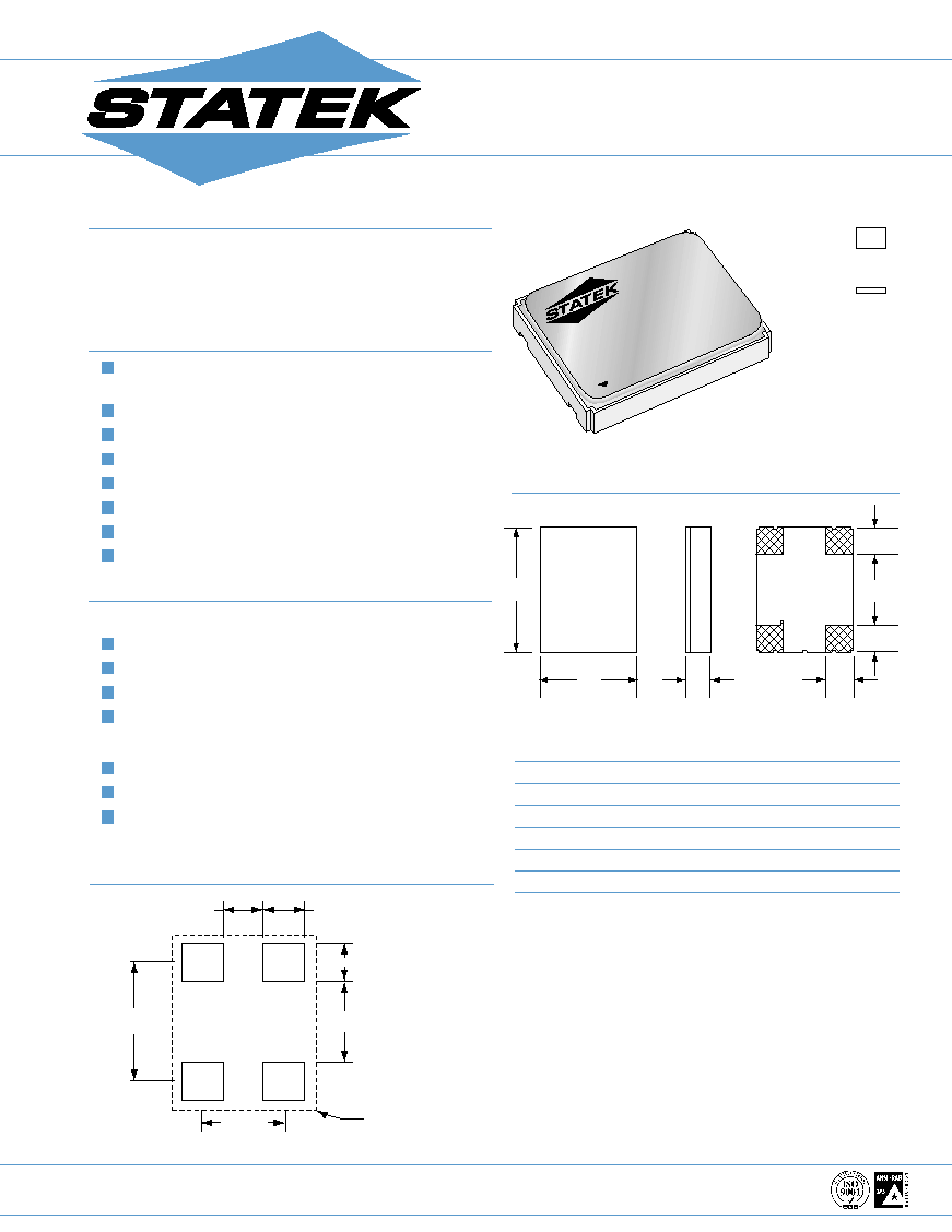
Ultra-Low Profile (1.3mm) Miniature Surface Mount
Crystal Oscillator
GM
4.19
M
A
TOP
BOTTOM
2
3
1
4
B
C
D
D
E
TYP.
MAX.
DIM
INCHES
mm
INCHES
mm
A
0.256
6.50
0.263
6.68
B
0.197
5.00
0.204
5.18
C*
0.051
1.30
0.055
1.40
D
0.055
1.40
E
0.060
1.52
0.070
1.78
Termination material is Au over Ni (SMI), solder dip (SM3) also available.
*SMI termination; SM3 = 0.063 in. (1.60 mm) Max.
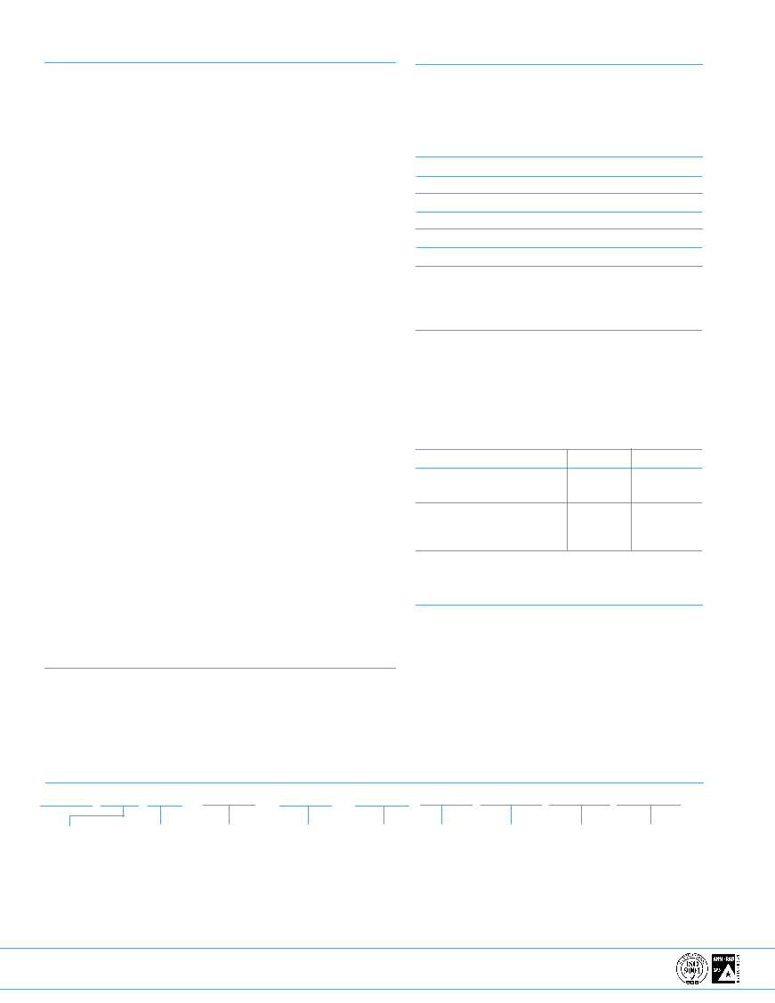
SUGGESTED LAND PATTERN
PACKAGE DIMENSIONS
.067(1.70)
.070(1.78)
.065(1.65)
.136(3.45)
GRID
PLACEMENT
COURTYARD
.
137(3.48)
.201(5.11)
actual size
side view
STATEK CORPORATION 512 N. MAIN ST., ORANGE, CA 92868 714-639-7810 FAX: 714-997-1256 www.statek.com
10116 - Rev C
SPECIFICATIONS
Specifications are typical at 25oC unless otherwise noted.
Specifications are subject to change without notice.
Supply Voltage
5V 10% (3V available)
Calibration
A:
0.01% (100ppm)
Tolerance*
B:
0.1%
C :
1.0%
Frequency
0
O
C to +50
O
C from
5 to 30ppm
Stability**
-10
O
C to +70
O
C from 10 to
50ppm
-40
O
C to +85
O
C from
20 to 100ppm
-55
O
C to +125
O
Cfrom 30
to 100ppm
Supply Current
14 mA for 50 MHz
12 mA for 40 MHz
10 mA for 30 MHz
8 mA for 24 MHz
TTL Load
10 @ 5V
CMOS Load
15 pF (up to 50 pF available)
Start-up Time
5 msec. MAX.
Rise/Fall Time
3 nsec. Typ., 6 nsec. MAX.
Duty Cycle
40% Min., 60% MAX.
Aging, first year
10 ppm MAX.
Shock, survival***
3,000g peak 0.3 msec., 1/2 sine
Vibration survival
20g rms 10-2000 Hz random
Operating Temperature -10
O
C to +70
O
C Commercial
-40
O
C to +85
O
C Industrial
-55
O
C to +125
O
C Military
* Tighter tolerances available
** Does not include calibration tolerances
*** High shock version available
Note: all parameters are measured at ambient temperature
with a 10M
and 10pF load at 5V
PACKAGING
CXOM - Tray Pack (Standard)
- 16mm tape, 7" or 13" reels (Optional)
Per EIA 481 (see data sheet 10109)
+
_
+
_
+
_
+
_
+
_
+
_
+
_
+
_
+
_
+
_
+
_
+
_
HOW TO ORDER CXOM SURFACE MOUNT CRYSTAL OSCILLATORS
CXOM
S
10
T
SM3
32 MHz
(
100ppm
/
100ppm
/
200ppm
/
I
)
* Enable available over 10MHz
** Other calibration fill in ppm
ABSOLUTE MAXIMUM RATINGS
Supply Voltage V
DD
-0.5V to 7.0V
Storage Temperature
-55
O
C to +125
O
C
Maximum Process Temperature 260
O
C, 10 seconds
TRUTH TABLE
PIN 1*
PIN 3
CXOM-10E
Low (0)
High (Z)
High (1)
Freq. Output
CXOM-10T
Low (0)
High (Z)
High (1)
Freq. Output
CXOM-10N
NC
Freq. Output
* Normally high (internal pull-up resistor)
PIN CONNECTIONS
1. Output Enable, INH (Tri-State) or NC
2. Ground
3. Output
4.
V
DD
Frequency
___
ENABLE VS. TRI-STATE
Enable: When pin 1 is low (0), the oscillator stops
oscillation.
Tri-state: When pin 1 is low, the oscillator is running.
However, the output buffer amplifier stops
functioning and output is in high impedance
(Z) state.
Enable
Tri-state
Current consumption
when pin 1 is low
Low
High
Output recovery delay
when pin 1 changes from
Delayed
Immediate
low (0) to high (1)
Temp. Range:
C = Commercial
I = Industrial
M = Military
S = Special
Total Frequency
Tolerance
Frequency
Stability over
Temp. Range
**Calibration
Tolerance
@ 25
0
C
(A)
(B)
(C)
*E = Enable
T = Tri-State
N = Neither
Blank = SM1(std.)
SM1 = Gold Plated
SM3 = Solder Dipped
10 = 10 TTL Load
"S" if special
or custom
design.
Blank if Std.