August 2006
Rev 1
1/8
8
DSILC6-4P6
ESD Protection for high speed interface
Main applications
Where transient over-voltage protection in ESD
sensitive equipment is required, such as:
Computers
Printers
Communication systems
Cell phone handsets and accessories
Video equipment
Description
The DSILC6-4P6 is a monolithic application
specific discrete dedicated to ESD protection of
high speed interfaces, such as USB 2.0, Ethernet,
display and camera serial interfaces.
The device is ideal for applications where both
reduced printed circuit board space and power
absorption capability are required.
Features
Diode array topology
4 line protection
5 V V
CC
protection
Pico capacitance: 2 pF typ.
Lead-free package
RoHS compliant
Benefits
Low capacitance between lines to GND for
optimized data integrity
Low PCB space consumption: 2.9 mm
2
max
No insertion loss to 2.0 GHz
High reliability offered by monolithic integration
MDDI specification compliant
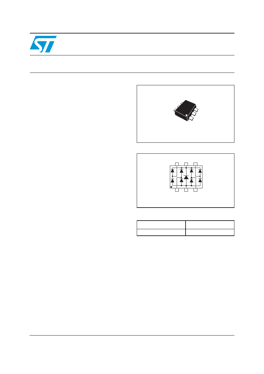
Functional diagram
Order Code
Complies with the following standards:
Part Number
Marking
DSILC6-4P6
G
IEC 61000-4-2 level 4:
15 kV (air discharge)
8 kV (contact discharge)
MIL STD 883E-Method 3015-7: class 3
HBM (Human Body Model)
I/O2
I/O3
I/O4
I/O1
VCC
GND
SOT-666
I/O4
I/O3
GND
VCC
I/O1
I/O2
Top view
www.st.com
Characteristics
DSILC6-4P6
2/8
1 Characteristics
Table 1.
Absolute ratings
Symbol
Parameter
Value
Unit
V
PP
Peak pulse voltage
IEC 61000-4-2 contact discharge
IEC 61000-4-2 air discharge
MIL STD883E - Method 3015-7
8
15
25
kV
T
stg
Storage temperature range
-55 to +150
�C
T
j
Maximum junction temperature
+125
�C
T
L
Lead solder temperature (10 seconds duration)
260
�C
Table 2.
Electrical characteristics (T
amb
= 25� C)
Symbol
Parameter
V
RM
Reverse stand-off voltage
I
RM
Leakage current
V
BR
Breakdown voltage
V
F
Forward voltage
V
CL
Clamping voltage
I
PP
Peak pulse current
Symbol
Parameter
Test Conditions
Value
Unit
Min
Typ
Max
I
RM
Leakage current
V
RM
= 5 V
0.5
�A
V
BR
Breakdown voltage
between V
BUS
and GND
I
R
= 1 mA
6
V
V
F
Forward voltage
I
F
= 10 mA
1
V
C
i/o-GND
Capacitance between I/O
and GND
V
I/O
= 0 V, F = 1 MHz,
V
OSC
= 30 mV
2
2.5
pF
V
I/O
= 1.65 V, V
CC
= 4.3 V,
F = 1 MHz, V
OSC
= 400 mV
1.5
1.8
pF
C
i/o-i/o
Capacitance between I/O
V
I/O
= 0 V, F = 1 MHz, V
OSC
= 30 mV
1
1.25
pF
V
I/O
= 1.65 V, V
CC
= 4.3 V,
F = 1 MHz, V
OSC
= 400 mV
0.75
0.9
pF
C
i/o-
GND
V
I/O
= 0 V, F = 1 MHz, V
OSC
= 30 mV
0.06
pF
C
i/o-i/o
V
I/O
= 0 V, F = 1 MHz, V
OSC
= 30 mV
0.05
pF
DSILC6-4P6
Characteristics
3/8
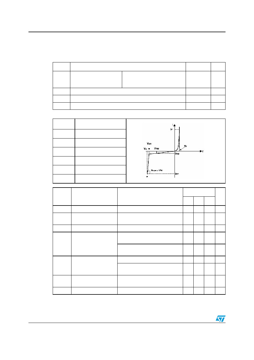
Figure 1.
Relative variation of leakage
current versus junction
temperature (typical values)
Figure 2.
Remaining voltage after
DSILC6-4P6 during ESD +15 kV
positive surge
1
10
100
25
50
75
100
125
T (�C)
j
V
=5V
BUS
I
[T
RM
j
] / I
[T
RM
j
=25�C]
50 ns/div
10
V/div
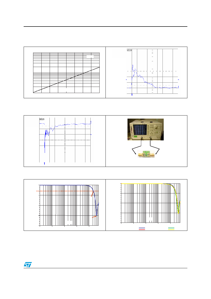
Figure 3.
Remaining voltage after
DSILC6-4P6 during ESD -15 kV
negative surge
Figure 4.
Test setup for frequency response
measurements
50 ns/div
10
V/div
VNA 8753E Agilent
In
Out
RF test board
Figure 5.
Frequency response for Line 1
Figure 6.
Frequency responses of all lines
-3dB
Fc=2.28GHz
F=4.13GHz
100.0k
1.0M
10.0M
100.0M
1.0G
-
20.00
-
15.00
-
10.00
-
5.00
0.00
F(Hz)
S21(dB)
100.0k
1.0M
10.0M
100.0M
1.0G
- 20.00
- 15.00
- 10.00
- 5.00
0.00
Line 1
Line 2
Line 3
Line 4
F(Hz)
S21(dB)
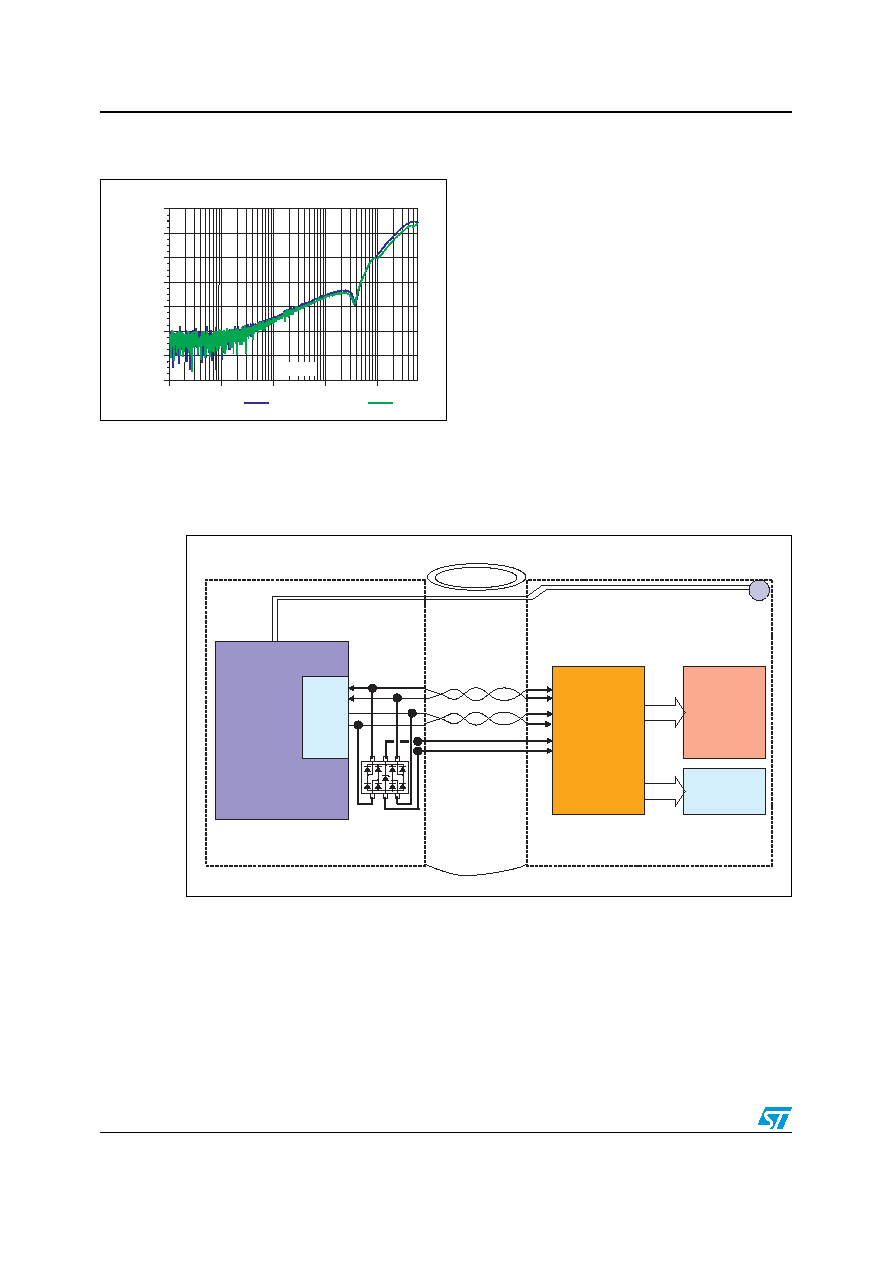
Application example implementation for MDDI
DSILC6-4P6
4/8
2
Application example implementation for MDDI
Figure 7.
Crosstalk results for lines 1/2
and 1/3
100.0k
1.0M
10.0M
100.0M
1.0G
- 140.00
- 120.00
- 100.00
- 80.00
- 60.00
- 40.00
- 20.00
0.00
Xtalk 1/2
Xtalk 1/3
F(Hz)
S21(dB)
MSM
MD
DI
Hos
t
Core
Analog Earpiece Audio
MDDI Client
& LCD
Controller
Chip (With
Frame
Buffer)
PRIMARY
LCD
SECONDARY
LCD
Lower Clamshell
Upper Clamshell
Hinge
MDDI Data (Host)
MDDI Strobe (Host)
Power & GND
DSILC6-4P6
DSILC6-4P6
Ordering information scheme
5/8
3
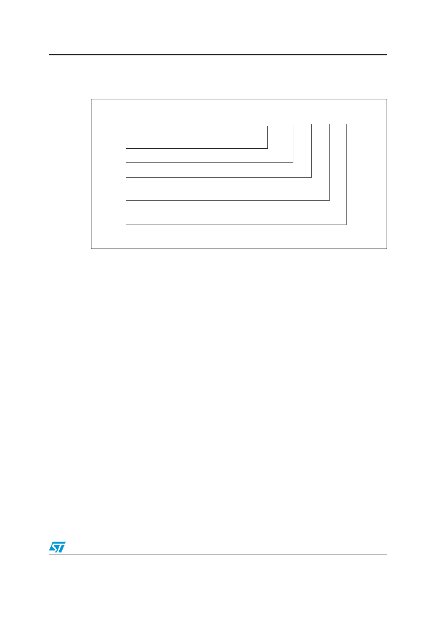
Ordering information scheme
DSI LC 6 - 4 xx
Product Designation
Low capacitance
Breakdown Voltage
Packages
6 = 6 Volts
4 = 4 lines
P6 = SOT-666
Number of lines protected