 | –≠–ª–µ–∫—Ç—Ä–æ–Ω–Ω—ã–π –∫–æ–º–ø–æ–Ω–µ–Ω—Ç: EFS2BCD | –°–∫–∞—á–∞—Ç—å:  PDF PDF  ZIP ZIP |

1/14
EFS
Æ
May 2000 - Ed: 5A
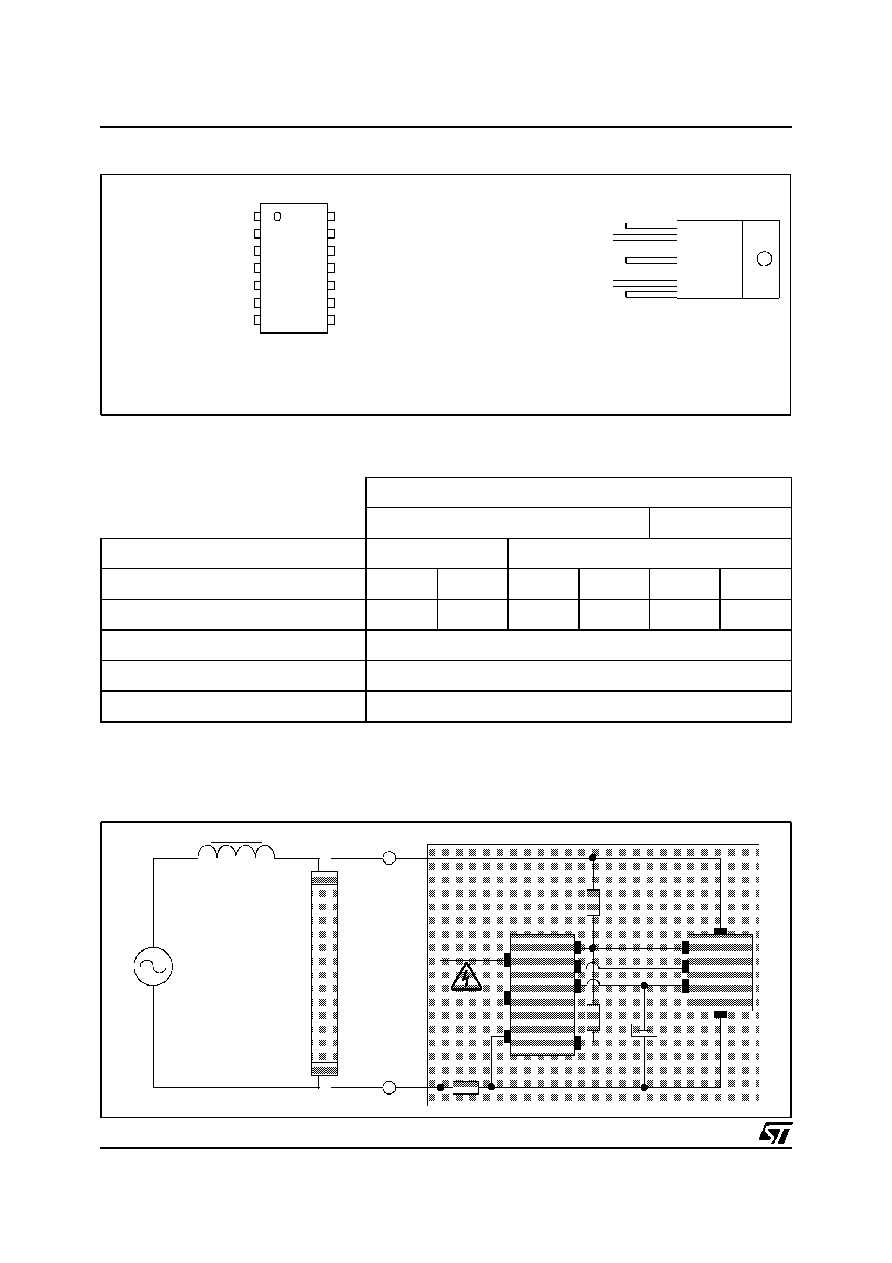
STARLIGHT-KIT
2-CHIPS SET FOR FLUORESCENT LAMP STARTER
PENTAWATT HV
EFS21-TL5
n
Very low component count: 2 chips + 7 passive
components
n
Meet
EN55015
standards
WITHOUT
EMI
capacitor
n
Extended life time of the fluorescent lamp due to
smooth and single shot ignition
n
High inherent reliability and extended life time
of the starter
BENEFITS
The EFS Kit is a 2 chips set used with 7 additional
passive components, for Glow switch Starter.
The
ASD
TM
(Application
Specific
Discretes)
includes a bi-directional Power Switch and a
Power Supply for the driver.
The driver provides a program to ensure a fully
optimised linear fluorescent lamp ignition.
DESCRIPTION
Application Specific Discretes
A.S.D.
TM
S014
EFS2A-CD
EFS2B-CD
n
VERY WIDE TEMPERATURE RANGE:
tube ignition from - 30 to + 85
∞
C
n
SINGLE SHOT IGNITION FROM -30 to 0
∞
C :
350mA, 1350V striking pulse
n
VERY WIDE POWER RANGE:
Fluorescent tube lamp ignition from 18 to 70W
n
EFS2B driver compatible with 50/60Hz
operation
n
SELECTABLE PREHEAT TIME:
EFS2A driver: 1.5s or 2.56s (50Hz)
EFS2B driver: 0.74s or 1.24s (50Hz)
EFS2B driver: 0.62s or 1.03s (60Hz)
n
8 STRIKING PULSES CAPABILITY:
for very cold environment or ageing lamp
n
STARTER SHUTDOWN WITH FAILED LAMP
FEATURES
TM : ASD is trademark of STMicroelectronics.
EFS
2/14
MAINS FREQUENCY
50Hz
60Hz
DRIVER VERSION
EFS2A
EFS2B
Pin 2 connection
GND
VCC
GND
VCC
GND
VCC
PREHEAT DURATION
1.5s
2.56s
0.74s
1.24s
0.62s
1.03s
ASD
TM
EFS21
LAMP POWER RANGE
18 to 70W (note 2)
AMBIENT TEMPERATURE RANGE
-30 to 85
∞
C (note1, note 2)
Note 1: below -20
∞
C, it is recommended to limit the lamp power range to 58W.
Note 2: the ignition temperature range is given with starting aid, as required in the IEC 81 and IEC 926 (ß6.3.1) standards.
EFS STARLIGHT-KIT PARTS SELECTION:
The EFS STARLIGHT-KIT answers effectively to linear fluorescent lamp ignition needs:
DRIVER: EFS2A-CD
and
: EFS2B-CD
ASD
TM
: EFS21-TL5
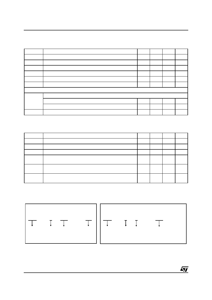
State tube detection
1
Shunt
4
Preheat select
2
to be grounded
7
to be grounded
3
to be grounded
5
to be grounded
6
14
G1
13
G2
12
VCC
11
GND
9
DO NOT CONNECT
8
to be grounded
10
to be grounded
SO14
Pentawatt HV
G1
1
G2
5
Vcc
2
Tube
3
GND
4
PIN CONNECTION (top view)
FLUORESCENT
LAMP
18W TO 70W
BALLAST
MAINS
4
9
7/8/10/11
2/3/5/6
14
13
12
2
5
1
3
4
150K
R
0.39
22
µ
F - 16V
DRIVER
ASD
TM
1
DO NOT
CONNECT
U1
U2
BASIC APPLICATION DIAGRAM

EFS
3/14
WORKING AREA
LAMP POWER (W)
Tamb (
∞
C)
(see note 2)
70 W
58 W
36 W
18 W
-30
-10
0
10
20
30
40
50
60
70
80
-20
90
RECOMMENDED LAMP POWER RANGE APPLICATION
Note 2: the ignition temperature range is given with starting aid, as required in the IEC 81 and IEC 926 (ß6.3.1) standards.
Symbol
Parameter
Value
Unit
Top
Operating Junction temperature range
-30 to +125
∞
C
Tstg
Storage temperature range
-55 to +150
∞
C
ABSOLUTE RATINGS (limiting values)
Symbol
Parameter
Value
Unit
Vcc
Maximum supply voltage
14
V
Ptot
Power dissipation
500
mW
ESD
Electrostatic discharge between any pins
Standard: MIL STD 883C Human Body Model
1
kV
V
SENSE
Input operating range
±
10
V
DRIVER: EFS2 A & EFS2B
Symbol
Parameter
Value
Unit
I
T(RMS)
RMS on-state current
Tcase = 90
∞
C
1
A
Tcase
I
T(RMS)
= 1A
t
OFF
= 0.16s
t
ON
= 0.75s
+ 120
∞
C
I
TSM
Surge peak on-state current
T
j
initial = 25
∞
C, tp = 10ms
Minimum repetitive rate periode : 1min.
15
A
V
DRM
V
RRM
Repetitive peak off-state voltage
600
V
ASD
TM
: EFS21
EFS
4/14
DRIVER
EFS
2
A/B
CD
-
EFS
2
1
TL5
-
Electronic
Fluorescent
Switch
Electronic
Fluorescent
Switch
Kit
Kit
Version
Digit
A: 50Hz
B: 50/60Hz
Version
Digit
SO14
Package
TL5:
Pentawatt HV Package
with lead forming
ASD
TM
ORDERING INFORMATION
ELECTRICAL CHARACTERISTICS (T
j
= 25
∞
C, unless otherwise specified)
Symbol
Parameter
Min.
Typ.
Max.
Unit
Vcc
Supply voltage in preheat mode
7
12
V
V
UVLO
Under voltage lock-out threshold
5
V
V
CCH
Supply limitation high in standby mode
6.8
7.7
8.7
V
V
CCL
Supply limitation low in standby mode
6.77
7.57
8.41
V
I
CC
Supply current in standby mode
440
450
475
µ
A
I
SO
Ignition current level Rsense = 0.39
280
350
420
mA
LAMP OFF STATE DETECTION
tc
Checking delay after zero crossing lamp voltage
EFS2A version
2.9
5.9
ms
EFS2B version
2.5
7.5
ms
V
REF
Internal reference voltage
1.12
1.26
V
DRIVER
Symbol
Parameter
Min.
Typ.
Max.
Unit
VT +
Positive on-state voltage
I
T
= 1.5A
tp = 500
µ
s
2.1
3.15
V
VT -
Negative on-state voltage
I
T
= 1.5A
tp = 500
µ
s
0.89
1.2
V
V
BR
Breakdown positive voltage I
DRM
= 5mA
t
p
= 10ms
1200
1350
1500
V
V
DCM
V
RCM
Non repetitive peak off-state voltage
Pin 1 = Pin 2 = Pin 4 = Pin 5
Repetitive rate : 3Hz
800
V
I
DRM
I
RRM
Leakage current, at V
DRM
/V
RRM
rated
Pin 1 = Pin 2 = Pin 4 = Pin 5
20
µ
A
I
H
Holding current
dI/dt = 9 A/ms
Pin1 = Pin 2 = Pin4 = Pin5
350
mA
ASD

EFS
5/14
4
9
7/8/10/11
3/5/6
14
13
12
2
5
1
3
4
R3
R4
R5
C1
DRIVER
ASD
2
U1
U2
R2
R1
THERMAL
FUSE
R6
D1
4
Vcc
GND
OPEN
one of the tracks
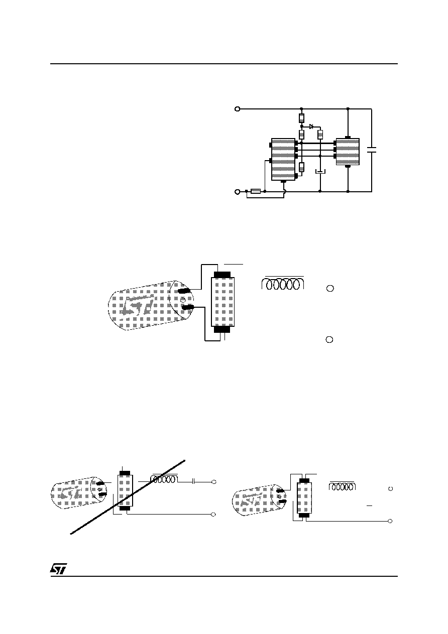
DEMONSTRATION BOARD DIAGRAM
Application Conditions
AC mains
Single
230V - 50Hz
Single
120V - 60Hz
Twin series 230V / 50Hz or
single 115V / 50Hz
Lamp Power Range
18 to 70W
18 to 36W
Ambient Temperature Range
-30 to + 85
∞
C (note 3)
Recommended Components
ASD version
EFS21
Driver version
EFS2A or EFS2B
EFS2B
EFS2A or EFS2B
R1, R2
30k
- 0.125W - 5%
15k
- 0.125W - 5%
R3
130k
- 0.125W - 5%
R4
2.2k
- 0.25W - 5%
3.3k
- 0.25W - 5%
R5
0.39
- 0.25W - 5% (note 4)
R6
0.39k
- 0.25W - 5%
C1
22
µ
F - 16V - 20%
C2
BYD17K (800V)
Note 3: below -20
∞
C, it is recommended to limit the lamp power range to 58W.
Note 4: R5(Rsense) should have a 8 A, 10 ms surge capability.
RECOMMENDED COMPONENTS ACCORDING TO APPLICATION CONDITIONS
Pin 2 is the preheat time select pin. To select a short preheat time, drill to cut the Vcc to pin 2 track at the
metallic hole. To select a long preheat time, drill to cut the GND to pin 2 track. The layout must be
configured for either choice to avoid supply short circuit.
When the starter has to be protected against over-temperature, over-current or short circuit, it is
recommended to implement a thermal fuse in series with the starter.
To meet (IEC 926) standards, a capacitor (f.i. 5nF) can be connected between pin 3 and pin 4 of the ASD.
BOARD ASSEMBLY
DRILL and CUT the track
for SHORT preheat -->
for LONG preheat -->
PCB with Pentawatt HV and SO14
EFS
6/14
3
2
1
FLUORESCENT
TUBE
220V / 50HZ
BALLAST
V strike
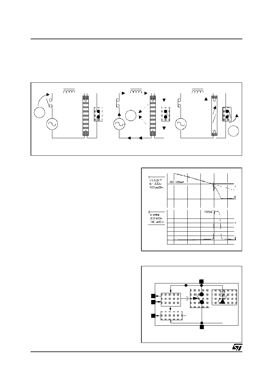
The mains voltage is applied
Preheating of the tube
Striking of the tube
PREHEAT
EFS STARLIGHT-KIT APPLICATION NOTE
he Starter is a bi-directional switch which performs two functions:
n
the preheat of the tube,
n
the ignition of the tube.
1/ THE AC POWER SWITCH: FUNCTIONAL DESCRIPTION
During the preheat period, the ASD
TM
is fully
conducting. The tube lamp is short circuited by the
starter, and the current flows through its filaments.
In these conditions, the lamp can not light up, but
the temperature of the lamp electrodes increases.
At the end of the preheat period, lamp filaments
are warm enough to emit electrons in the gas and
to permit the lamp ignition in good conditions. The
ASD
TM
switches off the preheating current . At this
moment, the ballast is equivalent to a current
generator (I=I
SO,
I
SO
= Switched Off current). As
the ASD
TM
switches off, the starter voltage
increases. The amplitude of this high voltage spike
is then clamped by the ASD
TM
(V
BR
1350 V). As
the starter and the lamp are in parallel, the striking
pulse is directly applied to the lamp. The
electromagnetic energy of the ballast is then
discharged through the lamp and the ASD
TM
.
Striking pulse
The AC SWITCH merges an auxiliary power
supply for the driver, a power clamping device
(1350V) and a bi-directional switch with his
execution pilot block.
2/ WHAT'S NEW IN THIS SWITCH?
GND
Vcc
G
2
TUBE
G
1
Power supply
ON / OFF
DRIVER
AC
SWITCH
HIGH
VOL
TAGE
CLAMPING
NEW EFS ASD

EFS
7/14
Present solutions work with a unidirectional
switch, like MOS transistors or GTO (Gate Turn
Off thyristor). As a starter is a bi-directional switch,
it is necessary to use a rectifier bridge (4 diodes of
1500V ). More, 2 or 3 diodes in series with the
GTO are required to get the necessary switch off
effect, and the whole is controlled with an analog
timer built around a small SCR.
The interest of a bi-directional switch arises itself:
a drastic reduction of the number of components,
and of course, a reduction of power losses (only 1
forward voltage instead of 5).
A lamp requires a minimum energy level to be ignited, but this energy depends especially on the lamp
temperature. The lower the temperature is, the more energetic the lamp strike is.
This energy stored in the ballast is directly proportional to the Switched Off current
I
E
L I
SO
SO
(
.
)
=
2
2
.
In other words, the required energy and of course the I
SO
level, are maximum for the minimum
temperature. Results based on experiments show that it is necessary to switch off a current of 350 mA to
strike a 58W tube at -30
∞
C (with a voltage amplitude clamped at 1200V and starting aid).
Therefore, the best way to strike a tube independently of the temperature is to keep the maximum I
SO
level
for all the temperature range. Unfortunately, the solution is not so simple to implement because the energy
level at ambient or warm temperature would be much important: the lamp would be ignited, but the lamp
lifetime would be shortened. This is why one of the innovations of the ASD
TM
is to modulate the striking
energy versus temperature (see feature hereafter).
3/ LAMP IGNITION FEATURE:
For freezing temperatures, the I
SO
level is maintained at 350 mA, and for positive temperatures, the I
SO
level decreases slowly.
GTO
SCR
1500V
Conventional discrete circuit (minimal version)
A.S.D.
TM
FEATURE
I.S.O.
350mA
200mA
Switched off current
versus ambient temperature

EFS
8/14
In order to reduce the number of components, an
auxiliary power supply is integrated in the ASD
TM
.
This active power supply works directly on the
mains and requires only a low voltage capacitor
16V - 22
µ
F. The operating mode of this supply
varies with the starter operating phase:
4/ AUXILIARY POWER SUPPLY:
DRIVER
ASD
VCC
G1
GND
TUBE
C SUPPLY
7.57
7.68
D1
R1
R2
R6
POWER SUPPLY SCHEMATIC
Supply operation during preheat phase:
During preheat phase, the driver manages alone the supply function (neither the driver nor D1 and R6 are
involved). A part of the current flowing through the ASD
TM
is used, at the beginning and at the end of each
positive mains half cycle, to charge the output capacitor.
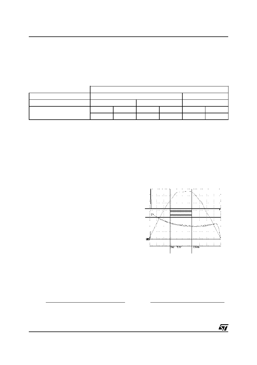
Supply operation during standby phase:
When the lamp is lit, the monitors its supply voltage (Vcc). At the beginning of each positive mains half
cycle, when Vcc is lower than 7.57V, the driver closes the ASD
TM
supply switch. The capacitor is charged
to provide the standby current of the driver. During this phase the tube lamp is short circuited by the
ASD
TM
. When the supply voltage reaches 7.68V, the driver opens the ASD
TM
supply switch. Since this
current is also flowing in the ballast, the supply turn off provides across the lamp an additional voltage
spike. After running few minutes the lamp becomes warm and this spike voltage naturally decreases.
SUPPLY DURING PREHEAT PHASE
Starter current
Starter voltage
at the ignition
5min after
ignition
SUPPLY DURING STANDBY PHASE
(Without E.M.I. Capacitor nor R6 nor D1)
To reduce dramatically this repetitive voltage spikes across the lamp, the R6 resistor with the diode D1
provide a part of the supply current. Thus, the ripple voltage of the supply voltage is reduced, as well as the
level of the switched off current. On the other hand, this increases the safety margin of the RF noise
(versus the IEC 55015 limits)

EFS
9/14
5/ THE DRIVER: FUNCTIONAL DESCRIPTION
GND
G 1
G 2
Preheat
Select
Vcc
Shunt
State
tube
Minimum
Power supply
State tube detection
(Striked / Off)
0 current synchro
ISO synchro
350mA
Pre-heat
period
counter
1,5s
or
2.5s
Current generator
30mA
8 attempts
Strikes counter
UVLO
Clock 1/8
EFS2A DRIVER Internal block diagram (50Hz operation)
ALGORITHM
1. At switch on:
At switch on, an integrated Under Voltage Lock Out function (UVLO) resets the driver as long as the supply
voltage stays below a safety level.
2. Preheat:
The ignition sequence begins with the preheat
phase. Two different duration's can be selected with
PIN 2 (see table EFS STARLIGHT-KIT PARTS
SELECTION page 2).
During this phase, the driver maintains the ASD
TM
in
a full ON-state making the starter equivalent to a
bi-directional conducting switch.
3. Ignition of the fluorescent tube:
At the end of the preheat period, the starter strikes
the fluorescent lamp.
For that, the driver reads continuously the current
through the starter. When the current reaches the
Switch Off level (I
SO
= 350mA), the driver turns off
the ASD
TM
. This induces a high voltage pulse across
the lamp. This pulse amplitude is limited by the
ASD
TM
(
1350V).
4. If the lamp fails to strike:
The driver detects the state of the tube (lit or off). If it
stays off during 8 mains cycles (loop 1), a new
preheat period, shorter than the first one, starts
again (loop 3), followed by a new ignition attempt.
The driver will try to fire the tube 8 times. If none of
the 8 attempts succeeds in striking the lamp, the driver turns in standby mode, and the whole starter is fully
stopped until the next mains removal and power supply reset.
5. If the lamp is ignited:
If the lamp is ignited, the driver stays in standby mode while monitoring the state of the lamp (loop 2).
During normal operation of the tube, this short pulse is masked by the lamp conduction. If the mains
interruption is really long enough to turn off completely the lamp, a new ignition sequence starts again (loop
3) with 8 other new possible attempts.
AC MAINS ON
UVLO
RESET
Preheat *
1.5s or 2.5s
Strike
Attempt = Attempt + 1
Preheat *
0.75s or 1.25s
Attempt <8
YES
YES
YES
NO
NO
NO
Loop 3
Loop 2
Tube
Ignited?
Fail = Fail + 1
Fail = 8
Fail = 0
Autosupply
Autosupply
Fail = 0
Attempt = 0
* see the preheat duration table ß 6
Loop 1
EFS
10/14
The driver determines the preheat duration by counting mains cycles. This numeric solution brings
naturally a good precision depending only on the mains frequency tolerance.
With the 2 driver versions, the EFS startlight-kit provides a choice of 4 preheat duration's. The following
table gives the preheat duration before the first ignition attempt. The seven next preheat duration's, in case
of unsuccessful ignition attempt, last the half of the first one
6/ PREHEAT PHASE DURATION 50-60Hz:
PREHEAT DURATION
MAINS FREQUENCY
50Hz
60Hz
DRIVER VERSION
EFS2A
EFS2B
EFS2B
Pin 2 connection
GND
VCC
GND
VCC
GND
VCC
1.5s
2.56s
0.74s
1.24s
0.62s
1.03s
During the ignition sequence or once the lamp is lit, the starter checks the state of the lamp (lit or off).
To determine this state, the driver reads the lamp voltage through the resistor bridge (R1+R2+R3, R4).
- If the lamp is off, its voltage equal the mains voltage.
- If the lamp is lit, its voltage is only 80 V (for a 58W lamp).
Thus the lamp state is determined by comparison of the lamp voltage with a programmed detection level.
7/ TUBE STATE DETECTION:
DL
DL
TC
min
TC
MAX
min
MAX
LIT Lamp
Voltage
OFF Lamp
Voltage
CORRECT SETTING = NO WAVEFORM
ACROSS THE GREY AREA
Tolerance effects:
Tolerances on resistors (R1, R2, R3 and R4) as
well as on the integrated comparator bring a
tolerance on the set detection level. Thus the
detection level is included in a range delimited by
the maximum and the minimum detection levels
(DL
MAX
DL
min
).
The driver checks the state of the lamp when
mains voltage is maximum, that is to say 5 ms after
the zero crossing mains voltage (50Hz). Here
again internal tolerances bring a tolerance on the
real checking moment (TC
min
TC
MAX
).
How to set the detection level?
Only the R4 resistor value can be set to adjust the detection level. Values of resitors R1 to R3 must match
values of the table RECOMMENDED COMPONENTS ACCORDING TO APPLICATION CONDITIONS of
the page 5. Practically the R4 resistor value has to be set so that neither the OFF lamp voltage nor the LIT
lamp voltage cross the grey area.
The DL
MAX
and DL
min
limits can be calculated as follows:
DL
x R
R
R
R
R
DL
MAX
MAX
MAX
MAX
=
+
+
+
1265
4
1
2
3
4
.
(
)
and
min
min
min
=
+
+
+
1122
4
1
2
3
4
.
(
)
min
min
min
x R
R
R
R
R
MAX
MAX
EFS
11/14
As required in the IEC 926 standard (ß11.5),
"starters which are interchangeable with glow
starters in accordance with IEC 155 shall contain
means for radio interference suppression, the
effect of which is equivalent to that of the radio
interference suppression capacitor prescribed in
7.12 of IEC 155".
The EFS starlight-kit is compatible with this 5nF
E.M.I. Capacitor which must be connected directly
across the ASD
TM
(between pin 3 "TUBE" and pin
4 "GND").
On the other hand, this E.M.I. capacitor increases
the striking pulse width of about 55% on positive
temperatures.
8/ E.M.I. CAPACITOR:
4
9
7/8/10/11
2/3/5/6
14
13
12
2
5
1
3
4
Rsense
DRIVER
ASD
TM
1
C
E.M.I.
8.1. Operation in single lamp configuration
The EFS STARLIGHT-KIT is ideal in the following configurations:
- Single Starter / 230V / 50Hz - Single Starter / 230V / 60Hz - Single Starter / 120V / 60Hz
AC
MAINS
T
U
B
E
Æ
Note 4: the different driver versions should be chosen according to the table "EFS STARLIGHT KIT PARTS SELECTION" page 2.
Note 5: Components to choose are listed in the table "RECOMMENDED COMPONENTS ACCORDING TO APPLICATION CONDITIONS"
page 5.
8.2. Operation with capacitor for power factor correction:
The EFS STARLIGHT-KIT is also suitable for magnetic ballast including front end parallel capacitor.
The EFS STARLIGHT-KIT is NOT suitable for magnetic ballast including front end serial capacitor.
T
U
B
E
Æ
LEADING MAGNETIC BALLAST WITH
SERIAL CAPACITOR
AC
MAINS
T
U
B
E
Æ
MAGNETIC BALLAST WITH SHUNT
PARALLEL CAPACITOR

EFS
12/14
8.3. Operation on the 230V/50Hz AC mains in twin tubes configuration
The EFS STARLIGHT-KIT is also suitable for the configurations Twin tubes Starter
Note 5: Components to choose are listed in the table "RECOMMENDED COMPONENTS ACCORDING TO APPLICATION CONDITIONS"
page 5.
The only electrical diagram difference consists of the R4 resistor which needs to be changed from 1 to
2.2k
. Without this modification, the starter will generate only one ignition attempt instead of 8 in case of
defective lamp; the loop 3 is removed from the algorithm described in page 9.
In the Twin Series 230V/50Hz configuration, the polarity of the two starters must be respected:
In case of no operation of starters, rotate one of the starters of 180
∞
on its socket.
230V / 50HZ
BALLAST
STARTER
SOCKET
FLUORESCENT
TUBE
OFF
OFF
ALIGHT
ALIGHT
Rotate of 180
∞
only one starter
AC
MAINS
230V
T
U
B
E
T
U
B
E
TWIN TUBE
EFS
13/14
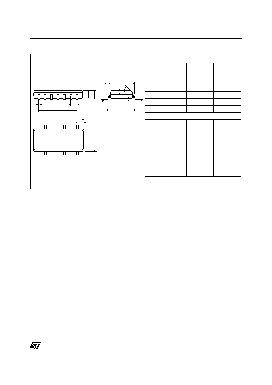
PACKAGE MECHANICAL DATA
SO14 (Driver)
b
e3
D
M
F
8
14
1
7
e
a2
A
L
G
S
E
a1
b1
c1
C
Dim.
Millimeters
Inches
Min.
Typ. Max. Min.
Typ. Max.
A
1.75
0.069
a1
0.1
0.2
0.004
0.008
a2
1.6
0.063
b
0.35
0.46 0.014
0.018
b1
0.19
0.25 0.007
0.010
C
0.5
0.020
c1
45
o
(typ.)
D
8.55
8.75 0.336
0.334
E
5.8
6.2
0.228
0.244
e
1.27
0.050
e3
7.62
0.300
F
3.8
4.0
0.150
0.157
G
4.6
5.3
0.181
0.208
L
0.5
1.27 0.020
0.050
M
0.68
0.027
S
8
o
(max.)
EFS
14/14
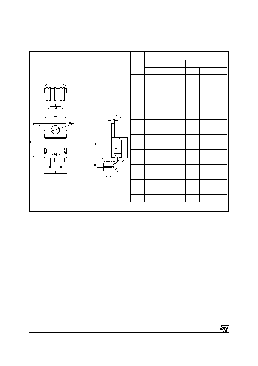
PACKAGE MECHANICAL DATA
Pentawatt HV with lead forming - TL5 (ASD
TM
)
REF.
DIMENSIONS
Millimeters
Inches
Min.
Typ.
Max.
Min.
Typ.
Max.
A
4.3
4.8
0.169
0.188
C
1.22
1.42
0.048
0.056
D
2.4
2.8
0.094
0.110
DIAM
3.65
3.85
0.144
0.152
E
0.35
0.45
0.014
0.018
F
0.65
0.75
0.026
0.030
G1
4.88
5.28
0.192
0.208
G2
7.42
7.82
0.292
0.308
H2
10.4
0.409
H3
10.05
10.4
0.396
0.409
L1
3.3
0.130
L2
14.24
14.64 0.560
0.576
L3
2.34
2.74
0.092
0.108
L5
2.6
3
0.102
0.118
L6
15.1
15.8
0.594
0.622
L7
6
6.6
0.236
0.260
R
0.5
0.020
Information furnished is believed to be accurate and reliable. However, STMicroelectronics assumes no responsibility for the consequences of
use of such information nor for any infringement of patents or other rights of third parties which may result from its use. No license is granted by
implication or otherwise under any patent or patent rights of STMicroelectronics. Specifications mentioned in this publication are subject to
change without notice. This publication supersedes and replaces all information previously supplied.
STMicroelectronics products are not authorized for use as critical components in life support devices or systems without express written ap-
proval of STMicroelectronics.
The ST logo is a registered trademark of STMicroelectronics
©
2000 STMicroelectronics - Printed in Italy - All rights reserved.
STMicroelectronics GROUP OF COMPANIES
Australia - Brazil - China - Finland - France - Germany - Hong Kong - India - Italy - Japan - Malaysia
Malta - Morocco - Singapore - Spain - Sweden - Switzerland - United Kingdom - U.S.A.
http://www.st.com