Application Specific Discretes
A.S.D.
TM
FLC01-200D
Æ
October 1999 Ed: 3A
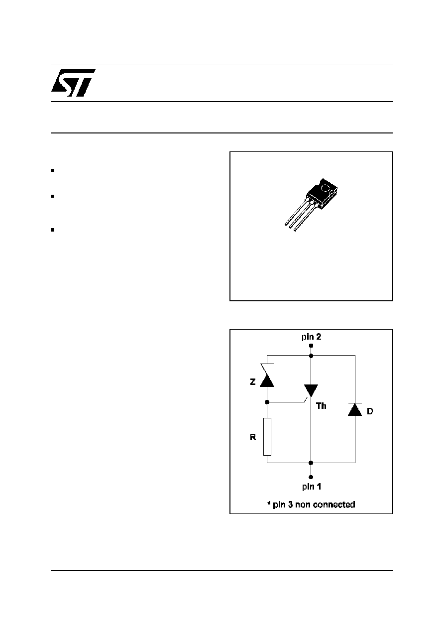
FIRE LIGHTER CIRCUIT
SOT82
(Plastic)
SPACE SAVING : MONOLITHIC FIRE LIGHTER
FUNCTION INTEGRATION
DEDICATED THYRISTOR STRUCTURE FOR
CAPACITANCE
DISCHARGE
IGNITION
OPERATION
HIGH PULSE CURRENT CAPABILITY
190A @ tp = 10
µ
s
FEATURES
-
The FLC01 is a high performance planar dif-
fused technology adapted to high temperature
and rugged environmental conditions.
-
It has been developed especially for capaci-
tance discharge operation. The main applica-
tions are gas lighter or ignitor such as :
cookers / gas boilers / gas hobs...
Th : Thyristor for switching operation.
Z : Zener diode to set the threshold voltage.
D : Diode for reverse conduction.
R : 2 k
resistor.
DESCRIPTION
FUNCTIONAL DIAGRAM
1
2
3
1/7
Symbol
Parameter
Value
Unit
Rth(j-a)
Thermal resistance junction to ambient
100
∞
C/W
THERMAL RESISTANCE
ORDERING INFORMATION
FLC
01 - 200
D
FIRE LIGHTER CIRCUIT
PACKAGE D : SOT82
V
RM
200 = 200 V
CIRCUIT NUMBER : 01 = scr + diode + zener + resistance
(pin 3 not connected)
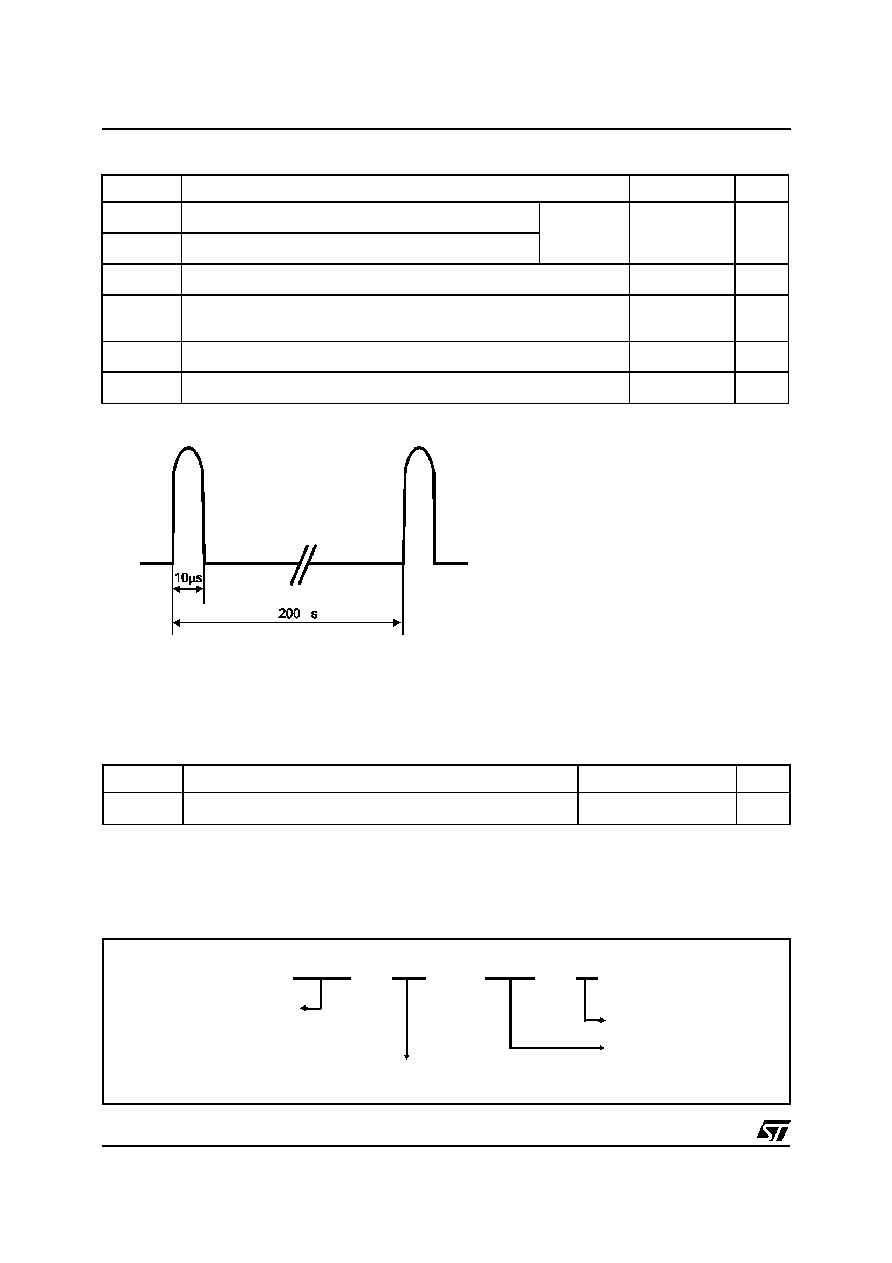
Symbol
Parameter
Value
Unit
I
TRM
Repetitive surge peak on state current for thyristor
tp = 10
µ
s
( note 1)
190
A
I
FRM
Repetitive surge peak on state current for diode
di/dt
Critical rate of rise time on state current
120
A/
µ
s
Tstg
Tj
Storage junction temperature range
Maximum junction temperature
- 40 to + 150
+ 125
∞
C
Toper
Operating temperature range
-30 + 120
∞
C
T
L
Maximum lead temperature for soldering during 10s
260
∞
C
Note 1 : Test current waveform
ABSOLUTE RATINGS (limiting values) : -30
∞
C < T
amb
< 120
∞
C
m
FLC01-200D
2/7
ELECTRICAL CHARACTERISTICS
Symbol
Parameters
V
RM
Stand-off voltage
V
BO
Breakover voltage
V
T
On-state voltage
V
F
Diode voltage drop
I
BO
Breakover current
I
RM
Leakage current
T
Thermal coefficient for V
BO
I
I
F
VF
V
T
IRM
IBO
I T
V
V
BO
V
RM
Symbol
Test Conditions
Value
Unit
V
F
I
F
= 2A
tp
1 ms
Tj = 25
∞
C
MAX
1.7
V
DIODE (D) PARAMETER
Symbol
Test conditions
Min
Typ
Max
Unit
I
RM
V
RM
= 200 V
Tj = 25
∞
C
1
µ
A
Tj = 125
∞
C
10
µ
A
V
BO
at I
BO
Tj = 25
∞
C
206
220
233
V
I
BO
at V
BO
Tj = 25
∞
C
0.5
mA
V
T
I
T
= 2A
tp
1ms
Tj = 25
∞
C
1.7
V
T
0.27
V/
∞
C
THYRISTOR (Th) and ZENER (Z) PARAMETERS
-20
0
20
40
60
80
100
0
0.5
1
1.5
2
2.5
Tj (
∞
C)
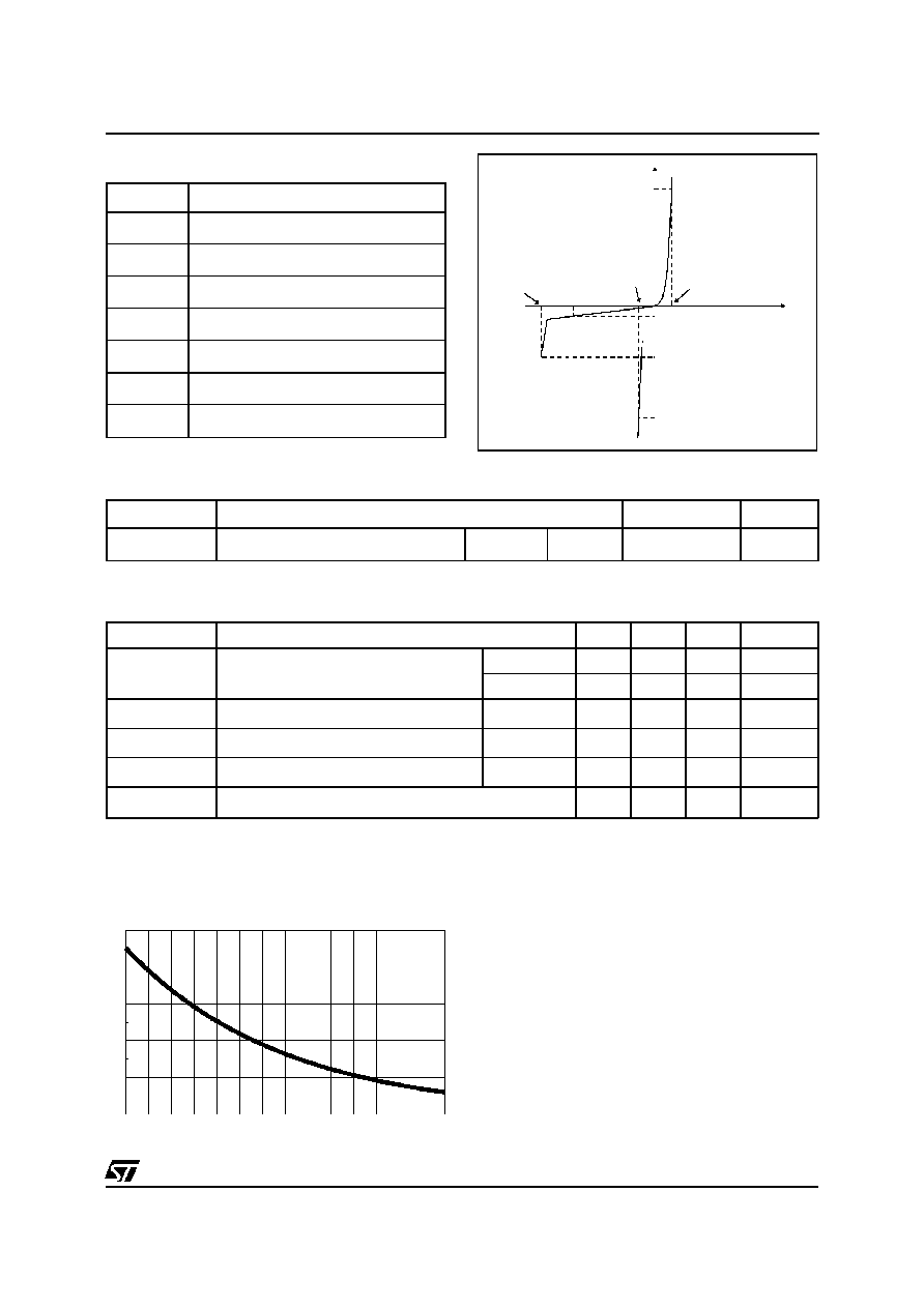
k = I
(Tj) / I
(25
∞
C)
BO
BO
Fig.1 : Relative variation of breakover current
(I
BO
) versus junction temperature
FLC01-200D
3/7
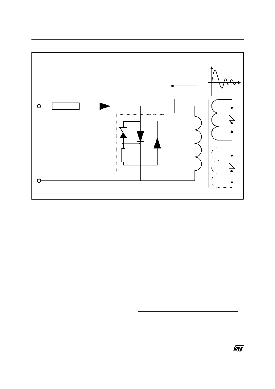
BASIC APPLICATION
Rs
Ds
c
D
Th
Z
R
Ic
AC
MAINS
Ic
t
The
applications
of
the
lighter
using
the
capacitance discharge topology operate in 2
phases :
PHASE 1
The energy coming from the mains is stored into
the capacitor C. For that, the AC voltage is rectified
by the diode Ds.
PHASE 2
At the end of the phase 1, the voltage across the
capacitor C reachesthe avalanche threshold of the
zener. Then a current flows through the gate of the
thyristor Th which fires.
The firing of the thyristor causes an alternating
current to flow through the capacitor C.
The positive parts of this current flow through C, Th
and the primary of the HV transformer.
The negative parts of the current flow through C, D
and the primaty of the HV transformer.
RS RESISTOR CALCULATION
The Rs resistor allows, in addition with the
capacitor C, to adjust the spark frequency and to
limitate the current from the mains. Its value shall
allow the thyristor Th to fire even in the worst case.
In this borderline case the system must fire with the
lower RMS mains voltage value while the
breakdown voltage and current of the FLC are at
the maximum.
The maximum Rs value is equal to :
Rsmax
=
(
V
AC
min.
2
) -
[
V
BO
max .
(
1
+
T.
(
T
amb
-
25
))
]
k . I
BO
* : see fig 1
FLC01-200D
4/7
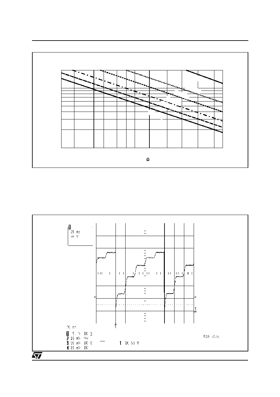
Fig. 2 : Spark frequency versus Rs and C
Fig. 3 : Voltage across the capacitance with Rs = 15k
, C = 1
µ
F and V
BO
= 225V.
4.7
6.8
10
12
15
18
22
27 30
1
2
3
5
10
20
F (Hz)
Rs (k )
Vac=220Vrms, Vbo=225V, Tamb=25
∞
C
C=3.3
F
µ
C=2.7
F
µ
C=2.2
F
µ
C=0.47
F
µ
C=0.47
F
µ
C=1
F
µ
C=1
F
µ
C=1.5
F
µ
C=1.5
F
µ
The couple Rs/C can be chosen with the previous
curve. Keep in mind the Rs maximum limit for
which the system would not work when the AC
mains is minimum. The next curve shows the
behavior with Rs=15k
and C=1
µ
F.
FLC01-200D
5/7

Fig. 4 : Peak current limit
6
8
10
12
14
110
120
130
140
150
160
170
180
190
tp (
µ
s)
ITRM (A)
Tjmax =125
∞
C
PEAK CURRENT LIMIT
T hi s co m pon en t is d es ig ned t o wi ths t an d
I
TRM
= 150A for a pulse duration of 10
µ
s for an
ambient temperature of 120
∞
C in repetitive surge.
The curve of peak current versus the pulse
duration allows us to verify if the application is
within the FLC operating limit.
POWER LOSSES (For 10
µ
s, see note 1)
To evaluate the power losses, please use the following equations :
For the thyristor : P = 1.18 x I
T(AV)
+ 0.035 I
2
T(RMS)
For the diode : P = 0.67 x I
F(AV)
+ 0.106 I
2
F(RMS)
FLC01-200D
6/7
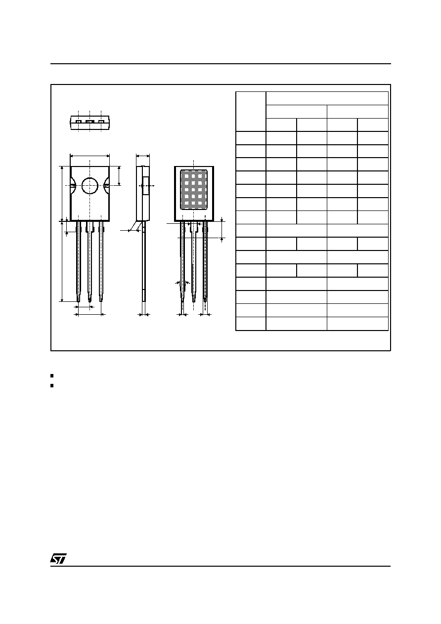
PACKAGE MECHANICAL DATA
SOT82 (Plastic)
A
F
C
B
H2
c1
D
e
e3
b1
O
b
I
H
V
REF.
DIMENSIONS
Millimeters
Inches
Min.
Max.
Min.
Max.
A
7.4
7.8
0.291
0.307
B
10.5
10.8
0.413
0.425
b
0.7
0.9
0.395
0.035
b1
0.49
0.75
0.019
0.029
C
2.4
2.7
0.094
0.106
c1
1.0
1.3
0.039
0.051
D
15.4
16.0
0.606
0.630
e
2.2 typ.
0.086 typ.
e3
4.15
4.65
0.163
0.183
F
3.8 typ.
0.149 typ.
H
2.54
0.100
H2
2.15 typ.
0.084 typ.
I
1.27 typ.
0.05 typ.
O
0.3 typ.
0.012 typ.
V
10
∞
10
∞
Marking : type number
Weight : 0.72 g.
Information furnished is believed to be accurate and reliable. However, STMicroelectronics assumes no responsibility for the consequences of
use of such information nor for any infringementof patents or other rights of third parties which may result from its use. No license is granted by
implication or otherwise under any patent or patent rights of STMicroelectronics. Specifications mentioned in this publication are subject to
change without notice. This publication supersedes and replaces all information previously supplied.
STMicroelectronics products are not authorized for use as critical components in life support devices or systems without express written ap-
proval of STMicroelectronics.
The ST logo is a registered trademark of STMicroelectronics
©
1999 STMicroelectronics - Printed in Italy - All rights reserved.
STMicroelectronics GROUP OF COMPANIES
Australia - Brazil - China - Finland - France - Germany - Hong Kong - India - Italy - Japan - Malaysia
Malta - Morocco - Singapore - Spain - Sweden - Switzerland - United Kingdom - U.S.A.
http://www.st.com
FLC01-200D
7/7