L3916A
SPEECH AND 14 MEMORY DIALER WITH LED DRIVER
SPEECH CIRCUIT
2 TO 4 WIRES CONVERSION
PRESENT THE PROPER DC PATH FOR THE
LINE CURRENT AND THE FLEXIBILITY TO
ADJUST IT AND ALLOW PARALLEL PHONE
OPERATION
PROVIDES SUPPLY WITH LIMITED CUR-
RENT FOR EXTERNAL CIRCUITRY
SYMMETRICAL HIGH IMPEDANCE MICRO-
PHONE INPUTS SUITABLE FOR DYNAMIC
ELECTRET
OR
PIEZOELECTRIC
TRANSDUCER
ASYMMETRICAL
EARPHONE
OUTPUT
SUITABLE FOR DYNAMIC TRANSDUCER
LINE LOSS COMPENSATION
INTERNAL MUTING TO DISABLE SPEECH
DURING DIALING
LIGHTED DIAL LED CONSUMING 25% OF
LINE CURRENT
DIALER CIRCUIT
32 DIGITS FOR LAST NUMBER REDIAL
BUFFER
18 DIGITS FOR 13 MEMORY REDIAL
ALLOW MIXED MODE DIALING IN EITHER
TONE OR PULSE MODE
PACIFIER TONE PROVIDES AUDIBLE INDI-
CATION OF VALID KEY PRESSED IN A
BUZZER OR/AND IN THE EARPHONE
TIMED PABX PAUSE
FLASH INITIATES TIMED BREAK: 585ms.
CONTINUOUS TONE FOR EACH DIGIT UN-
TIL KEY RELEASE
USES
INEXPENSIVE
3.579545MHz
CE-
RAMIC RESONATOR
POWERED FROM TELEPHONE LINE, LOW
OPERATING VOLTAGE FOR LONG LOOP
APPLICATION
DESCRIPTION
The device consists of the speech and the dialer.
It provides the DC line interface circuit that termi-
nates the telephone line, analog amplifier for
speech transmission and necessary signals for
either DTMF or loop disconnect (pulse) dialing.
March 2000
�
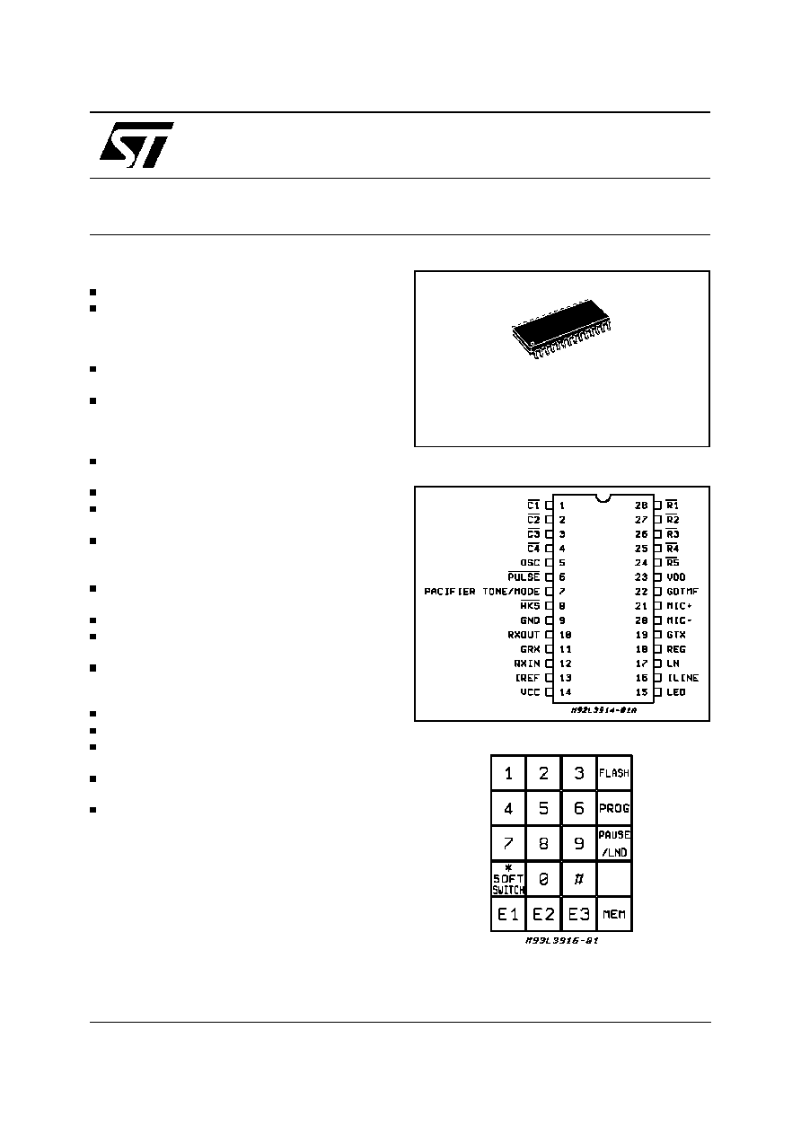
PIN CONNECTION (Top view)
KEYPAD CONFIGURATION
SO28
ORDERING NUMBER: L3916AD
Note: PAUSE/LND:
PAUSE and LND functions are sharing the same key with different
sequence. Hereafter, PAUSE and LND keys are referring to the same
key.
1/14

DESCRIPTION (continued)
When mated with a tone ringer, a complete tele-
phone can be produced with just two ICs.
The DC line interface circuit develops its own line
voltage across the device and it is adjustable by
external resistor to suit different country's specifi-
cation.
The speech network provides the two to four
wires interface, electronic switching between dial-
ing and speech and automatic gain control on
transmit and receive.
The dialing network buffers up to 32 digits into the
LND memory that can be later redialed with a sin-
gle key input. Additionally, another 13 memories
(including 3 emergency memories) of 18 digits
memory is available. Users can store all 13 sig-
nalling keys and access several unique functions
with single key entries. These functions include:
Pause/Last Number Dialed (LND), Softswitch,
Flash.
The FLASH key simulates a timed hook flash to
transfer calls or to activate other special features
provided by the PABX or central office.
The PAUSE key stores a timed pause in the num-
ber sequence. Redial is then delayed until an out-
side line can be accessed or some other activity
occurs before normal signaling resumes.
A LND key input automatically redials the last
number dialed.
FUNCTION PIN DESCRIPTION
C1, C2, C3, C4, R5, R4, R3, R2, R1
Keyboards inputs. Pins 1, 2, 3, 4, 24, 25, 26, 27,
28. The one chip phone interfaces with either the
standard 2-of-9 with negative common or the sin-
gle-contact (Form A) keyboard.
BLOCK DIAGRAM
L3916A
2/14

A valid keypad entry is either a single Row con-
nected to a single Column or GND simultaneously
presented to both a single Row and a single Col-
unm.
In its quiescent or standby state, during normal
off-hook operation, either the Rows or the Col-
umns are at logic level 1 (V
DD
). Pulling one input
low enables the on chip oscillator. Keyboard
scanning then begins.
Scanning consists of Rows and Columns alter-
nately switching high through on chip pullups. Af-
ter both a Row and Column key have been de-
tected, the debounce counter is enabled and any
noise (bouncing contacts, etc) is ignored for a de-
bounce period (TKD) of 32ms. At this time, the
keyboard is sampled and if both the Row and Col-
umn information are valid, the information is buff-
ered into the LND location. After scanning starts,
the row and column inputs will assume opposite
states.
In the tone mode, if two or more keys in the same
row or if two or more keys in the same column are
depressed a single tone will be output. The tone
will corresponds to the row or column for which
the two keys were pushed. This feature is for test-
ing purposes, and single tone will not be redialed.
Also in the tone mode, the output tone is continu-
ous in the manual dialing as long as the key is
pushed. The output tone duration follows the Ta-
ble 1. When redialing in the tone mode, each
DTMF output has 100ms duration, and the tone
separation (inter signal delay) is 100ms.
Table 1: Output Tone Duration
Key-Push Time, T
Tone Output
T<= 32ms
32ms < = T < = 100ms +
Tkd
T > = 100ms + Tkd
No output, ignored by
one chip phone.
100ms Duration
Output Duration = T - Tkd
OSC
Output. Pin 5. Only one pin is needed to connect
the ceramic resonator to the oscillator circuit. The
other end of the resonator is connected to GND
(pin 8). The nominal resonator frequency is
3.579545MHz and any deviation from this stand-
ard is directly reflected in the Tone output fre-
quencies. The ceramic resonator provides the
time reference for all circuit functions. A ceramic
resonator with tolerance of
�
0.25% is recom-
mended
PULSE
Output. Pin 6. This is an output consisting of an
open drain N-Channel device. During on-hook,
pulse output pin is in high impedance and once off-
hooked, it will be pulled high by external resistor.
MODE/PACIFIER TONE
Input (MODE). Pin 7. MODE determines the di-
aler's default operating mode. When the device is
powered up or the hookswitch input is switched
from on-hook (V
DD
) to off-hook (GND), the default
determines the signalling mode. A V
DD
connec-
tion defaults to tone mode operation and a GND
connection defaults to pulse mode operation.
When dialing in the pulse mode, a softswitch fea-
ture will allow a change to the tone mode when-
ever the * key is depressed. Subsequent * key in-
puts will cause the DTMF code for an * to be
dialed.. The softswitch will only switch from pulse
to tone. After returning to on-hook and back to off-
hook, the phone will be in pulse mode. Redial by
the LND key or the MEM key will repeat the soft-
switch.
Output (PACIFIER TONE). Pin 7. In pulse mode,
all valid key entries activate the pacifier tone. In
tone
mode, any non DTMF entry (FLASH,
PROG, PAUSE, LND, MEM, E1, E2 and E3), acti-
vates the pacifier tone. The pacifier tone provides
audible feedback, confirming that key has been
properly entered and accepted. It is a 500Hz
square wave activated upon acceptance of valid
key input after the 32ms debounce time. The
square wave terminates after a maximum of
75ms or when the valid key is no longer present.
The pacifier tone signal is simultaneously sent to
earphone and the buzzer. The buzzer can be re-
moved without affecting this function.
HKS
Input. Pin 8. This is the hookswitch input to the one
chip phone. This is a high impedance input and
must be switched high for on-hook operation or low
for off-hook operation. A transition on this input
causes the on chip logic to initialize, terminating
any operation in progress at the time. The signaling
mode defaults to the mode selected at pin 7. Fig-
ures 1 and 2 illustrate the timing for this pin.
GND
Pin 9 is the negative line terminal of the device.
This is the voltage reference for all specifications.
RXOUT, GRX, RXIN
RXOUT (pin 10), GRX (pin 11) and RXIN (pin 12).
The receive amplifier has one input RXIN and a
non inverting output RXOUT. Amplification from
RXIN to RXOUT is typically 31dB and it can be
adjusted between 11dB and 41dB to suit the sen-
sitivity of the earphone used. The amplification is
proportional to the external resistor connected be-
tween GRX and RXOUT.
FUNCTION PIN DESCRIPTION (continued)
L3916A
3/14

IREF
Pin 13. An external resistor of 3.6kOhm con-
nected between IREF and GND will set the inter-
nal current level. Any change of this resistor value
will influence the microphone gain, DTMF gain,
earphone gain and sidetone.
V
CC
Pin 14, V
CC
is the positive supply of the speech
network. It is stabilized by a decoupling capacitor
between V
CC
and GND. The V
CC
supply voltage
may also be used to supply external peripheral
circuits.
LED
Pin 15. Lighted dial indicator. The LED connected
to this pin will light up when the telephone is off-
hook and consuming 25% of the line current.
I
LINE
Pin 16. A recommended external resistor of
20ohm is connected between I
LINE
and GND.
Changing this resistor value will have influence on
microphone gain, DTMF gain, sidetone, maximum
output swing on LN and on the DC characteristics
(especially in the low voltage region).
LN
Pin 17. LN is the positive line terminal of the de-
vice.
REG
Pin 18. The internal voltage regulator has to be
decoupled by a capacitor from REG to GND. The
DC characteristics can be changed with an exter-
nal resistor connected between LN and REG or
between REG and I
LINE
.
GTX, MIC�, MIC+
GTX (pin 19), MIC� (pin 20) and MIC+ (pin 21).
The one chip phone has symmetrical microphone
inputs. The amplification from microphone inputs to
LN is 51.5dB and it can be adjusted between 43.5
and 51.5dB. The amplification is proportional to ex-
ternal resistor connected between GTX and REG.
GDTMF
Pin 22. When the DTMF input is enabled, the mi-
crophone inputs and the receive amplifier input will
be muted and the dialing tone will be sent to the
line. The voltage amplification from GDTMF to LN
is 40dB. Final ouput level on LN can be adjusted
via the external resistor connected between
GDTMF and GND through a decoupling capaci-
tor. A confidence tone is sent to the earphone
during tone dialing. The attenuation of the confi-
dence tone from LN to Vear is �32dB typically.
V
DD
Pin 23. V
DD
is the positive supply for the dialing
network and must meet the maximum and mini-
mum voltage requirements.
DEVICE OPERATION
During on-hook all keypad inputs are high imped-
ance internally and it requires very low current for
memory retention. At anytime, Row and Column
inputs assume opposite states at off-hook. The
circuit verifies that a valid key has been entered
by alternately scanning the Row and Column in-
puts. If the input is still valid following 32ms of de-
bounce, the digit is stored into memory, and dial-
ing
begins
after
a
pre-signal
delay
of
approximately 40ms (measured from the initial
key closure). Output tone duration is shown in Ta-
ble 1.
The device allows manual dialing of an indefinite
number of digits, but if more than 32 digits are di-
aled, it will "wrap around". That is, the extra digits
beyond 32 will be stored at the beginning of LND
buffer, and the first 32 digits will no longer be
available for redial.
Table 2: DTMF Output Frequency
Key Input
Stadard
Frequency
Actual
Frequency
% Deviation
ROW 1
ROW 2
ROW 3
ROW 4
697
770
852
941
699.1
766.2
847.4
948.0
+0.31
�0.49
�0.54
+0.74
COL 1
COL 2
COL 3
1209
1336
1477
1215.9
1331.7
1471.9
+0.57
�0.32
�0.35
NORMAL DIALING
D1
D2
D3
....etc
Normal dialing is straighforward, all keyboard en-
tries will be stored in the buffer and signaled in
succession.
PROGRAMMING AND REPERTORY DIALING
To program, enter the following:
PROG D1 D2 D3. . . Dn MEM (Location 0-9)
or
PROG
D1
D2. . . .Dn
E1-E3
During programming, dialing is inhibited.
FUNCTION PIN DESCRIPTION (continued)
L3916A
4/14

To dial a number from repertory memory (HKS
must be low), enter the following:
MEM (Location 0-9) or E1-E3
To save the last number dialed, enter the follow-
ing:
PROG MEM (location 0-9) or E1-E3
HOOK FLASH
D1
FLASH
D2
...etc
Hook flash may be entered into the dialed se-
quence at any point by keying in the function key,
FLASH. Flash consists of a timed break of
585ms, 300ms or 100ms depending on the Mask
option. When a FLASH key is pressed, no further
key inputs will be accepted until the hookflash
function has been dialed. The key input following
a FLASH will be stored as the initial digit of the
new number, overwriting the number dialed be-
fore the FLASH, unless it is another FLASH.
FLASH key pressed immediately after hookswitch
or LND will not clear the LND buffer unless digits
are entered following the FLASH key.
Example:
FLASH
LND not cleared
LND
FLASH
LND not cleared
LND
FLASH
D1
D2
LND buffer will contain D1, D2
PAUSE/LAST NUMBER DIALED
If the PAUSE/LND key is pressed right after off
hook or FLASH key, it is considered as LND, if it
is pressed after a digit, it will be considered as
PAUSE.
LAST NUMBERED DIALED
OFF-HOOK PAUSE/LND or FLASH PAUSE/LND
Last number dialing is accomplished by entering
the PAUSE/LND key.
PAUSE
OFF-HOOK D1
PAUSE/LND
D2
...etc
A pause may be entered into the dialed sequence
at any point by keying in the special function key,
PAUSE/LND. Pause inserts a 3.1 second delay
into the dialing sequence. The total delay, includ-
ing pre-digit and post-digit pauses is shown in Ta-
ble 3.
Table 3: Special Function Delays
Each delay shown below represents the time re-
quired after the special function key is depressed
until a new digit is dialed. The time is considered
"FIRST" key if all previous inputs have been com-
pletely dialed. The time is considered "AUTO" if in
redial, or if previous dialling is still in progress.
Function
First/Auto
Delay (seconds)
Pulse
Tone
SOFTSW ITCH
FIRST
AUTO
0.2
1.0
PAUSE
FIRST
AUTO
2.6
3.4
3.0
3.1
SOFTSWITCH FUNCTION USING TONE/PULSE
MODE SWITCH
When dialing in Pulse mode after off-hook,
switching TONE/PULSE mode switch from Pulse
to Tone will cause the device to change the sig-
naling mode into tone signal and store the soft-
switch function in the LND memory for redial. To
redial the softswitch function (mixed mode dialing)
in the pulse mode after going on-hook and back
to off-hook, you have to switch the TONE/PULSE
mode switch back to pulse mode either before go-
ing on-hook or after off-hook or during on-hook.
Subsequent mode change from Tone to Pulse will
change the signaling mode to pulse dialing se-
quence but this mode change will not be stored in
.the LND memory.
When dialing in Tone mode after off-hook, a
switching of TONE/PULSE mode Switch from
Tone to Pulse will cause the device to change the
signaling mode into pulse mode but this mode
change will not be stored in the LND memory.
When LND key is pressed in Tone mode after go-
ing off-hook, the device will output all tone sig-
nals.
A pacifier tone of 75ms is provided after 32ms de-
bounce time when switching from Pulse to Tone
mode.
Redial by the LND key will repeat the mixed dial-
ing sequence in Pulse mode.
FUNCTION PIN DESCRIPTION (continued)
L3916A
5/14