 | –≠–ª–µ–∫—Ç—Ä–æ–Ω–Ω—ã–π –∫–æ–º–ø–æ–Ω–µ–Ω—Ç: L6585DTR | –°–∫–∞—á–∞—Ç—å:  PDF PDF  ZIP ZIP |
TARGET SPECIFICATION
This is preliminary information on a new product foreseen to be developed. Details are
subject to change without notice.
January 2006
Rev1
1/9
9
L6585D
PFC and Ballast Control IC
Features
Pre-heating and ignition phases independently
programmable
Programmable and precise End-of-life
protection compliant with all ballast
configurations
Half-bridge over-current control
Ignition voltage control
Automatic Re-lamp
1.25
µ
s dead time
3% Oscillator precision
Transition mode PFC with over-current
protection
PFC over-voltage protection and feedback
disconnection
Under-voltage lock-out
Applications
Electronic ballast
SO-20
www.st.com
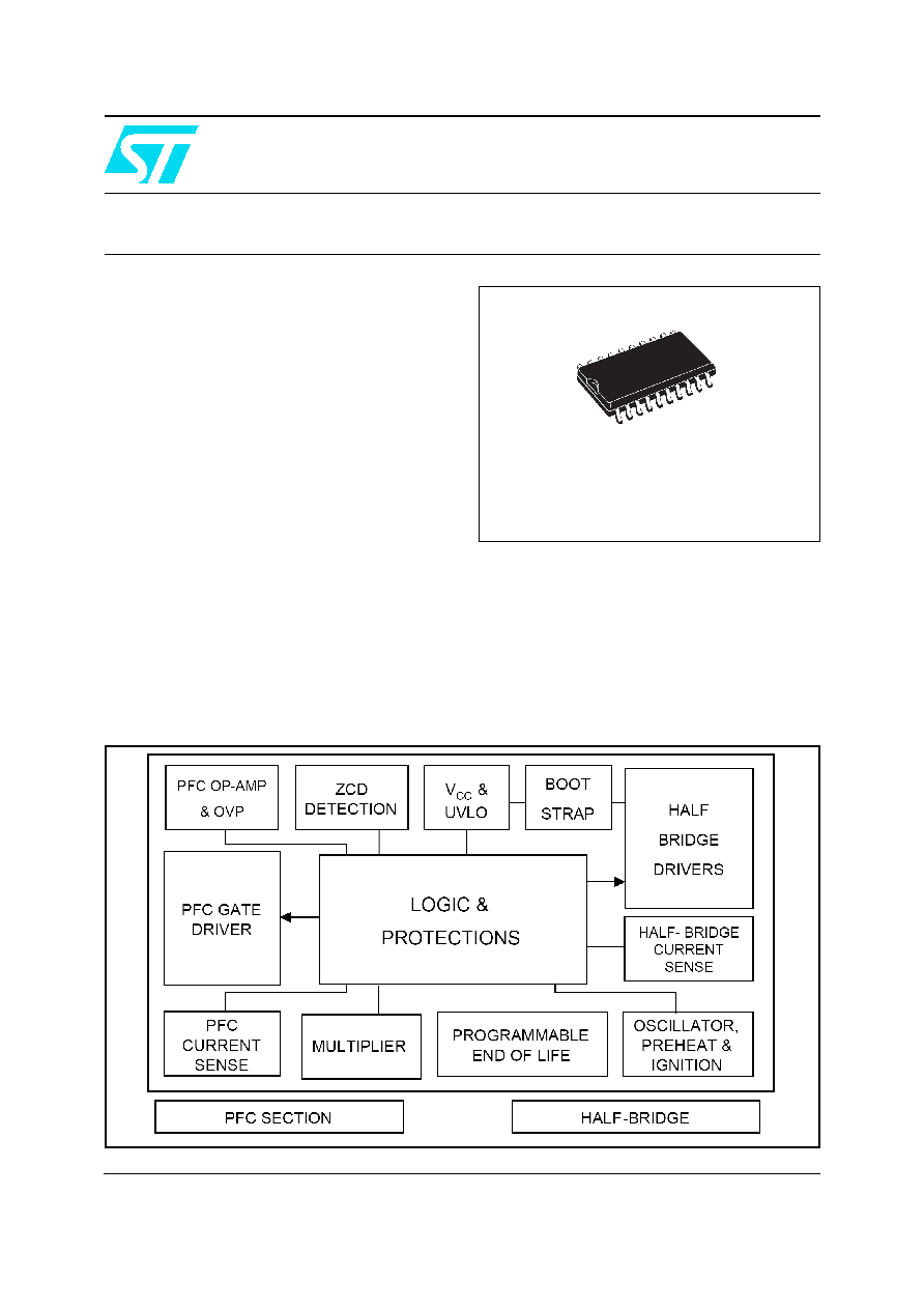
Block diagram

Contents
L6585D
2/9
Rev1
Contents
1
Technical Overview . . . . . . . . . . . . . . . . . . . . . . . . . . . . . . . . . . . . . . . . . . 3
2
Pin Connections and Internal Schematic . . . . . . . . . . . . . . . . . . . . . . . . 4
3
Mechanical Data . . . . . . . . . . . . . . . . . . . . . . . . . . . . . . . . . . . . . . . . . . . . 5
4
Order codes . . . . . . . . . . . . . . . . . . . . . . . . . . . . . . . . . . . . . . . . . . . . . . . . 7
5
Revision history . . . . . . . . . . . . . . . . . . . . . . . . . . . . . . . . . . . . . . . . . . . . 8

L6585D
Technical Overview
Rev1
3/9
1 Technical
Overview
The L6585 is a ballast control IC with integrated Power Factor Corrector (PFC), designed in
High-voltage BCD Off-line technology. This one-chip solution replaces a half bridge
controller, a PFC controller, the relevant drivers and the logic necessary to build an
electronic ballast.
The pre-heating and ignition durations are independently settable as well as the half-bridge
switching frequencies for each operating phase (pre-heating, ignition and normal mode) to
serve many different lamp types. Another outstanding feature is the capability of limiting the
voltage applied to the lamp to a constant value during the ignition phase.
The PFC section operates in Transition Mode. The highly linear multiplier includes a special
circuit, able to reduce AC input current distortion, that allows wide-range-mains operation
with an extremely low THD, even over a large load range.
Some IC features, like the under voltage lock-out and the PFC over-voltage and feedback
disconnection controls can assure lamp protection. Furthermore, a double threshold
comparator on the half bridge current sense provides a sort of current control and avoids the
MOSFETs working in the capacitive mode. A double threshold comparator on the PFC
current sense prevents the inductor saturation.
Other features like the automatic re-lamp for lamp replacing, the failure to strike and the
End-Of-Life control, simplify the lamp management. The programmability of the EOL
windows comparator thresholds makes the L6585 the only lighting IC compliant with either
"lamp-to-ground" or "block capacitor-to-ground" configurations.
The driver of the PFC is able to provide 120mA (source) and 250mA (sink) and the drivers
of the half-bridge provide 170mA source and sink.
Pin Connections and Internal Schematic
L6585D
4/9
Rev1
2
Pin Connections and Internal Schematic
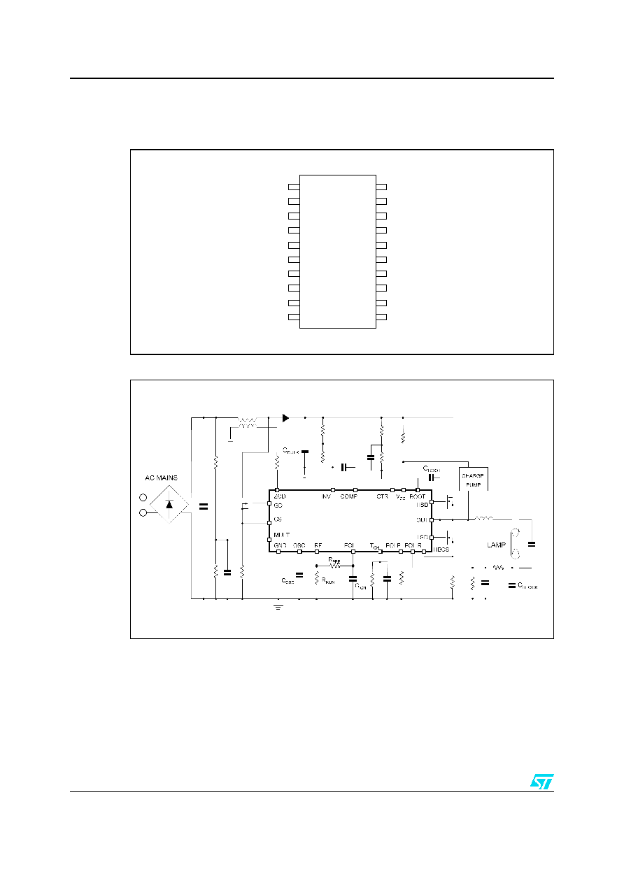
Figure 1.
Pin connection (through top view)
Figure 2.
Typical System Block Diagram
BOOT
HSD
OUT
GND
LSD
VCC
COMP
INV
ZCD
PFC CS
PFG
HBCS
EOLP
EOL-R
CTR
MULT
EOI
TCH
OSC
RF

L6585D
Mechanical Data
Rev1
5/9
3 Mechanical
Data
In order to meet environmental requirements, ST offers these devices in ECOPACK
Æ
packages. These packages have a Lead-free second level interconnect. The category of
second Level Interconnect is marked on the package and on the inner box label, in
compliance with JEDEC Standard JESD97. The maximum ratings related to soldering
conditions are also marked on the inner box label. ECOPACK is an ST trademark.
ECOPACK specifications are available at:
www.st.com
.
Mechanical Data
L6585D
6/9
Rev1
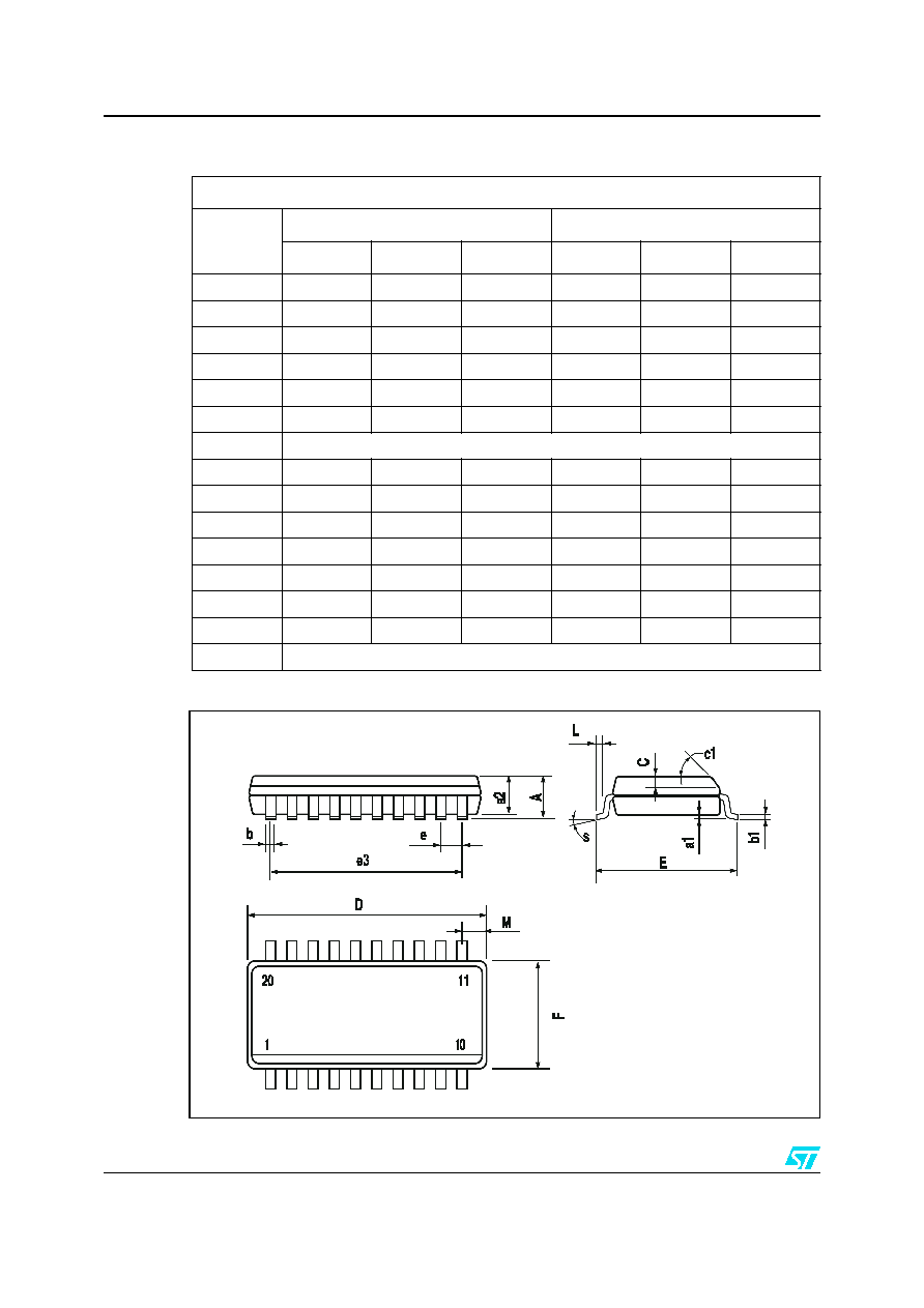
Figure 3.
Package Dimensions
Table 1.
SO-20 Mechanical Data
Dimensions
Ref.
mm.
inch
Min.
Typ.
Max.
Min.
Typ.
Max.
A 2.65
0.104
a1 0.1
0.2
0.004
0.008
a2 2.45
0.096
b 0.35
0.49
0.014
0.019
b1 0.23
0.32
0.009
0.012
C 0.5
0.020
c1 45∞
(typ.)
D 12.60
13.00
0.496
0.512
E 10.00
10.65
0.393
0.419
e 1.27
0.050
e3 11.43
0.450
F 7.40
7.60
0.291
0.300
L 0.50
1.27
0.020
0.050
M 0.75
0.029
S 8∞
(max.)

L6585D
Order codes
Rev1
7/9
4 Order
codes
Table 2.
Order codes
Part Number
Package
Shipment
L6585D
SO-20
Tube
L6585DTR
SO-20
Tape and Reel

Revision history
L6585D
8/9
Rev1
5 Revision
history
Table 3.
Document revision history
Date
Revision
Changes
12-Jan-2006
1
Initial release.

L6585D
Revision history
Rev1
9/9
Information furnished is believed to be accurate and reliable. However, STMicroelectronics assumes no responsibility for the consequences
of use of such information nor for any infringement of patents or other rights of third parties which may result from its use. No license is granted
by implication or otherwise under any patent or patent rights of STMicroelectronics. Specifications mentioned in this publication are subject
to change without notice. This publication supersedes and replaces all information previously supplied. STMicroelectronics products are not
authorized for use as critical components in life support devices or systems without express written approval of STMicroelectronics.
The ST logo is a registered trademark of STMicroelectronics.
All other names are the property of their respective owners
© 2006 STMicroelectronics - All rights reserved
STMicroelectronics group of companies
Australia - Belgium - Brazil - Canada - China - Czech Republic - Finland - France - Germany - Hong Kong - India - Israel - Italy - Japan -
Malaysia - Malta - Morocco - Singapore - Spain - Sweden - Switzerland - United Kingdom - United States of America
www.st.com