L9686
AUTOMOTIVE DIRECTION INDICATOR
ADVANCE DATA
RELAY DRIVER IN CAR DIRECTION
INDICATORS
FLASH FREQUENCY DOUBLES TO INDI-
CATE LAMP FAILURE
DUMP PROTECTION (
±
80 V)
REVERSE BATTERY PROTECTION
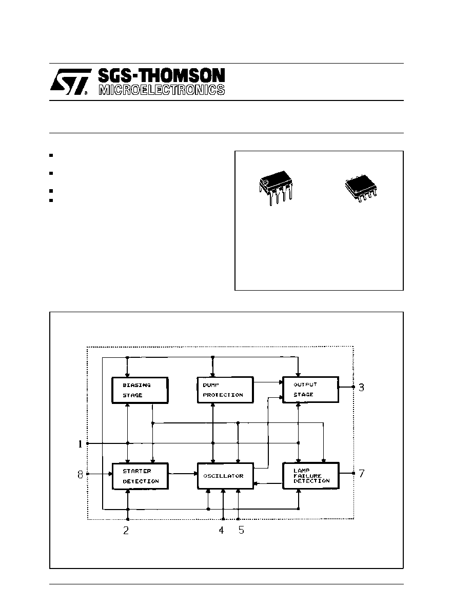
DESCRIPTION
The L9686 is a two frequency oscillator particu-
larly suitable as relay driver for flashing light con-
trol in automotive applications. The circuit may be
also used for other warning lamps like "handbrake
on" etc. The lamp failure detection is given by
doubling the flash repetition frequency. The
L9686 is supplied in minidip 8-lead and SO8 plas-
tic packages.
This is advanced information on a new product now in development or undergoing evaluation. Details are subject to change without notice.
May 1995
BLOCK DIAGRAM
MINIDIP
SO8
ORDERING NUMBERS:
L9686
L9686D
1/7

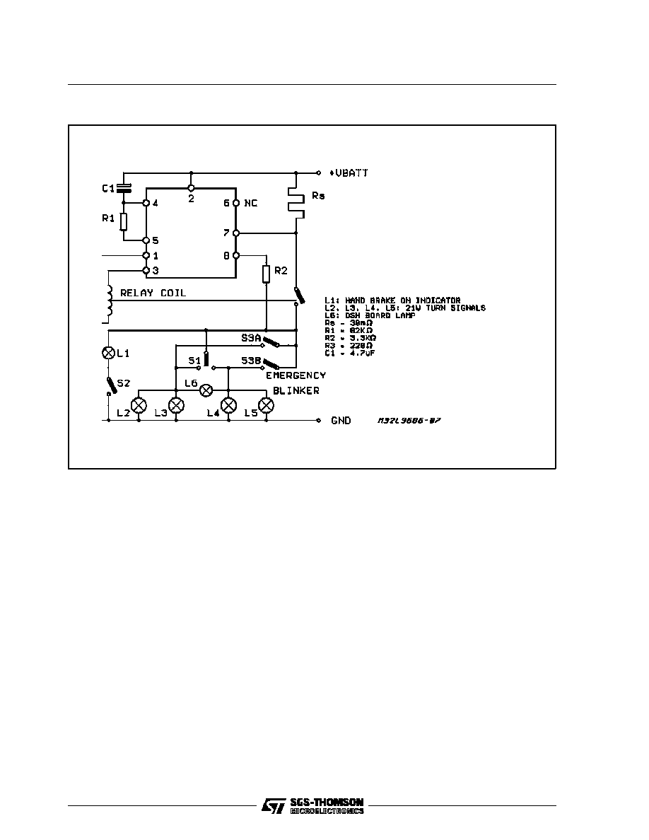
FUNCTIONAL DESCRIPTION
The circuit is designed to drive the direction indi-
cator flasher relay. The application circuit shows
the typical system configuration with the external
components. Its consists of a network (R
1
C
1
) to
determine the oscillator frequency, shunt resistor
(R
S
) to detect defective bulbs and two current lim-
iting resistors (R
2
/R
3
) to protect the IC against
load dump transients.
The lightbulbs L
2
, L
3
, L
4
, L
5
, are the turn signal in-
dicators with the dashboard-light L
6
. The S
1
switch
position is sensed
across
resistor R
2
and R
lamp
by input 8. The flashing cycle is started
by closing S
1
: then, after a delay time t
d
typically
equal to 1.5 ms, the relay is actuated and the pin
3 goes high switching on the corresponding
lamps L
2
, L
3
, (or L
4
, L
5
). These lamps will flash at
the oscillator frequency not depending on the bat-
tery voltage value (8 - 18 V). The flashing cycle
stops and the circuit is reset to the initial position
when the switch S
1
is open.
The lamp failure detection function senses the
current through the shunt resistor R
S
. When one
of the lightbulbs is defective the voltage drop
across R
S
is reduced to a half and the failure is
indicated by doubling the flashing frequency.
ELECTRICAL CHARACTERISTICS (≠ 20
∞
C < T
amb
<, 100
∞
C, 8V < V
S
< 18V unless otherwise speci-
fied.)
Symbol
Parameter
Test Condition
Min.
Typ.
Max.
Unit
V
S
Operating Voltage
8
18
V
V2 ≠ V1
Clamping Voltage
see note 1
27
34
V
V2 ≠ V3
Output Saturation Voltage
I
RL
= 250mA
1.7
V
R2
Starter Resistance
see note 2
3.6
K
K
N
Oscillator Constant K
N
(normal
Operation)
Fn = 1/KnRoCo
Osc. Frequency
1.27
1.74
C
T
Temperature Coefficient of Kn
See Note 3
≠1.5
10-3
1/
∞
C
D.C.
Duty Cycle (normal operation)
45
50
55
%
K
C
Oscillator Constant K
C
(lamp failure detection)
F
C
= 1KcRoCo
Osc. Frequency
0.53
0.74
DC
LF
Duty Cicle (lamp failure
detection)
35
40
45
%
I
Q
Current Consumption Relay off
I
pin 1
V
S
= 8V
V
S
= 13.5V
V
S
= 18V
2.2
2.7
3.3
3.9
4.3
4.7
mA
mA
mA
V
th
Lamp Failure Threshold
(see note 4)
R
3
= 220
V
S
= 13.5V
≠20 < T
amb
< 100
∞
C
65
85
95
mV
Notes : 1.
This voltage is the threshold used to protect the circuit against overvoltage : if V
bat
is > than this threshold, the relay will be on
and the voltage across the circuit wil l maintain constant increasing the current in the protective resistor R
3
.
2.
This is the maximum value for operation. This value must be higher than 1 K Ohms in order to limit the current in pin 8 during
dumps. A recommended value for application should be 1,5 K Ohms.
3.
The external leakage from the blinker unit to ground must be with an equivalent resistor higher than 5,6 K Ohms to avoid para-
sitic operation when the switch S
1
is off.
4.
This temperature coefficient is usefull to compensate the drift of the external timing network (R
1
, C
1
).
5.
This threshold is calculated for a 20 m Ohm shunt. The threshold is dependant of V
bat
as the bulb current.
L9686
3/7