1/5
L9813
April 2004
This is preliminary information on a new product now in development. Details are subject to change without notice.
1
FEATURES
8-18V Supply Operating Range
16 MHz Maximum Oscillator Frequency
8 MHz Maximum Internal Clock Frequency
Fully Static operation.
Low consumption (
100mA) mode.
-40∞C to + 150∞C Temperature Range
ROM: 8Kbytes
Data RAM: 256 bytes
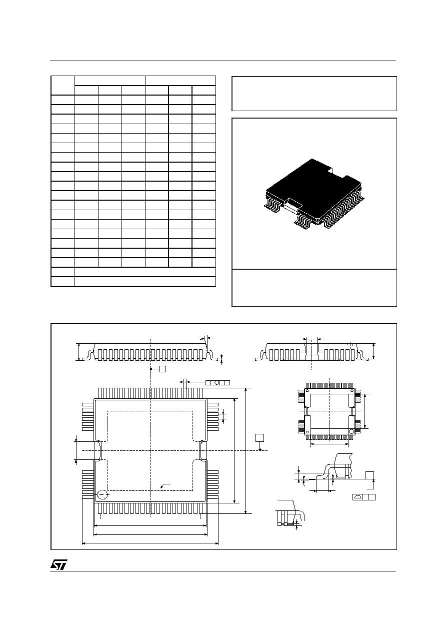
64 pin HiQuad package
5 multifunctional bidirectional I/O lines
16-bit Timer, featuring:
≠ 2 Input Captures
≠ 2 Output Compares
≠ External Clock input
≠ PWM and Pulse Generator modes
UART peripheral including Bus line interface
according ISO9141 specifications
Serial Peripheral Interface (SPI).
8-bit Analog-to-Digital Converter with 2
dedicated inputs.
Programmable Watchdog for system integrity
Master Reset and Power-On Reset
Two 200m
Half-Bridges, Two 400m
Half-
Bridges for sequential driving of 3 DC motors.
50m
High-Side driver (Defroster function)
300m
High-Side driver (Sidemarker function)
400m
High-Side driver (Puddle Lamp
function)
300m
High-Side driver + Parallel Voltage
Regulator (Electro Chrome function
8-bit Data Manipulation
63 basic Instructions and 17 main Addressing
Modes
8 x 8 Unsigned Multiply Instruction
True Bit Manipulation
Complete Development Support on DOS/
WINDOWSTM Real-Time Emulator
Full Software Package on DOS/WINDOWSTM
(C-Compiler, Cross-Assembler, Debugger)
2
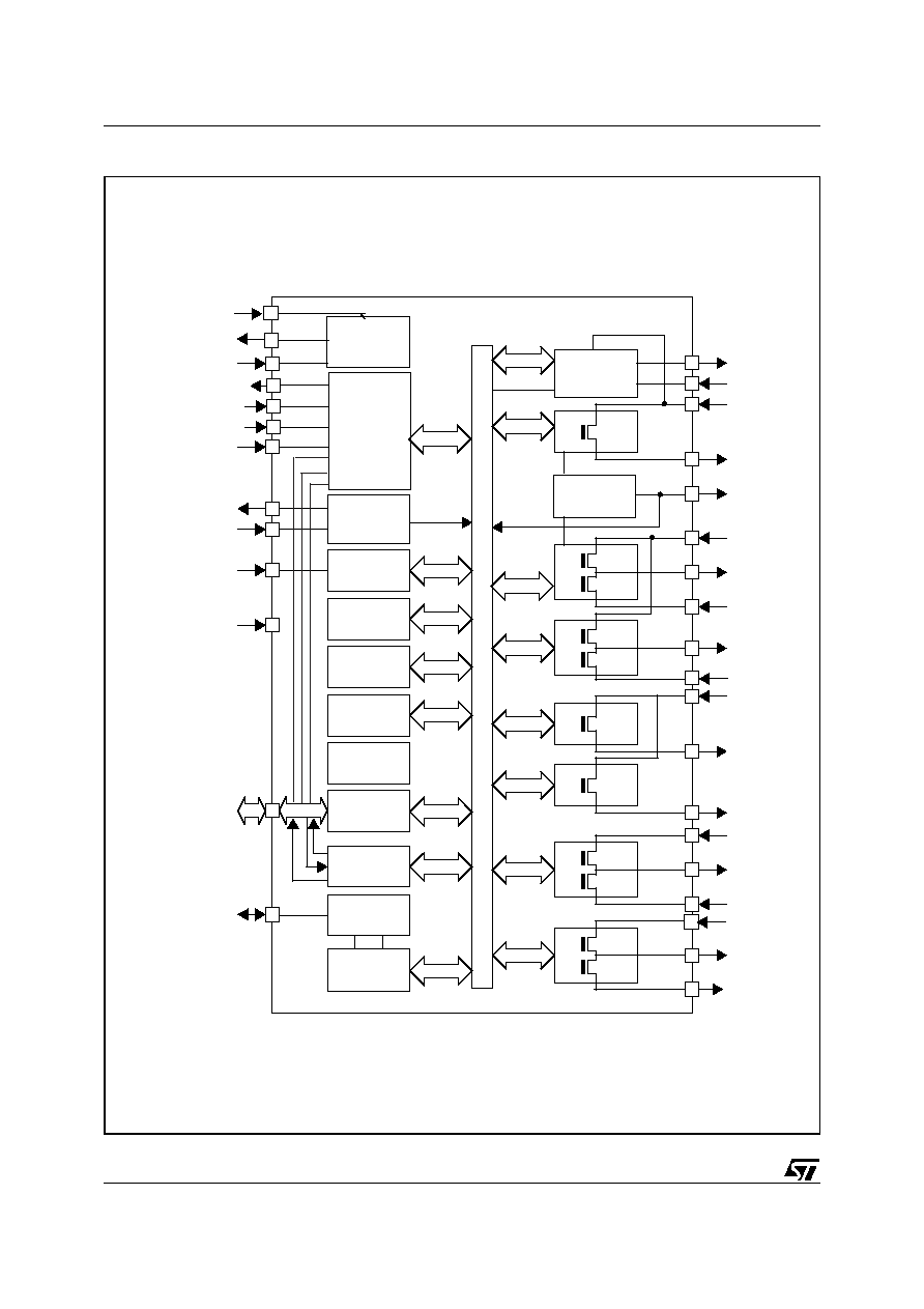
DESCRIPTION
The L9813 Microcontroller Unit (MCU) is a mem-
ber of the ST7 family of Microcontrollers.
The device is based on an industry-standard 8-bit
core and features an enhanced instruction set.
The device is normally operated at an 16MHz os-
cillator frequency. Under software control, the
L9813 may be placed in either Wait, Slow or Halt
modes, thus reducing power consumption.
The enhanced instruction set and addressing
modes afford real programming potential. In addi-
tion to standard 8-bit data management, the L9813
features true bit manipulation, 8x8 unsigned multi-
plication and indirect addressing modes.
The device includes an internal oscillator, CPU,
ROM/OTP/EPROM, RAM, 5 I/O lines and the fol-
lowing on-chip peripherals: Analog-to-Digital con-
verter (ADC) with 5 multiplexed analog inputs,
industry standard synchronous SPI and asynchro-
nous SCI serial interfaces, digital Watchdog, 16-
bit Timer, 2 Input Captures and 2 Output Com-
pares.
HiQUAD64
DATA BRIEF
SUPER SMART MIRROR WITH EMBEDDED MCU
Table 1. Order Codes
Part Number
Package
L9813
HiQUAD64
REV. 2

Information furnished is believed to be accurate and reliable. However, STMicroelectronics assumes no responsibility for the consequences
of use of such information nor for any infringement of patents or other rights of third parties which may result from its use. No license is granted
by implication or otherwise under any patent or patent rights of STMicroelectronics. Specifications mentioned in this publication are subject
to change without notice. This publication supersedes and replaces all information previously supplied. STMicroelectronics products are not
authorized for use as critical components in life support devices or systems without express written approval of STMicroelectronics.
The ST logo is a registered trademark of STMicroelectronics.
All other names are the property of their respective owners
© 2004 STMicroelectronics - All rights reserved
STMicroelectronics GROUP OF COMPANIES
Australia - Belgium - Brazil - Canada - China - Czech Republic - Finland - France - Germany - Hong Kong - India - Israel - Italy - Japan -
Malaysia - Malta - Morocco - Singapore - Spain - Sweden - Switzerland - United Kingdom - United States
www.st.com
5/5
L9813