 | –≠–ª–µ–∫—Ç—Ä–æ–Ω–Ω—ã–π –∫–æ–º–ø–æ–Ω–µ–Ω—Ç: L9822E | –°–∫–∞—á–∞—Ç—å:  PDF PDF  ZIP ZIP |

L9822E
OCTAL SERIAL SOLENOID DRIVER
ADVANCE DATA
.
EIGHT LOW R
DSon
DMOS OUTPUTS
(0.5
AT I
O
= 1A @ 25
∞
C V
CC
= 5V
±
5%)
.
8 BIT SERIAL INPUT DATA (SPI)
.
8 BIT SERIAL DIAGNOSTIC OUTPUT FOR
OVERLOADAND OPENCIRCUIT CONDITIONS
.
OUTPUT SHORT CIRCUIT PROTECTION
.
CHIP ENABLE SELECT FUNCTION (active low)
.
INTERNAL 36V CLAMPING FOR EACH OUT-
PUT
.
CASCADABLE
WITH
ANOTHER
OCTAL
DRIVER
.
LOW QUIESCENT CURRENT (10mA MAX.)
.
PACKAGE MULTIWATT15, PowerSO20 AND
SO20L
DESCRIPTION
The L9822E is an octal low side solenoid driver
rea lized in Multipower-BCD technology particularly
suited for driving lamps, relays and solenoids in au-
BLOCK DIAGRAM
PowerSO20
SO20L (16+2+2)
Multiwatt15
ORDERING NUMBERS: L9822E (Multiwatt15)
L9822EPD (Power SO20)
L9822ED (SO20L )
tomotive environment. The DMOS outpts L9822E
has a very low power consumption.
Data is transmitted serially to the device using the
Serial Peripheral Interface (SPI) protocol.
The L9822E features the outputs status monitoring
function.
MULTIPOWER BCD TECHNOLOGY
September 1994
This is advanced information on a new product now in development or undergoing evaluation. Details are subject to change without notice.
1/11

PowerSO20
Multiwatt15
SO20L
PIN CONNECTIONS (top view)
THERMAL DATA
Symbol
Parameter
Multiwatt15
SO20L
PowerSO20
Unit
R
th j-case
Thermal Resistance Junction-Case
Max.
2
25
1.5
∞
C/W
R
th j-amb
Thermal Resistance Junction-Ambient
Max.
35
70
60
∞
C/W
ABSOLUTE MAXIMUM RATINGS
Symbol
Parameter
Value
Unit
V
CC
DC Logic Supply
≠ 0.7
7
V
V
O
Output Voltage
≠ 0.7
40
V
I
I
Input Transient Current
(CE, SI, SCLK, RESET, SO) :
Duration Time t = 1s,
V
I
< 0
V
I
> V
CC
≠ 25
+ 25
mA
mA
I
Odc
Continous Output Current (for each output)
Int. Limited
A
T
j
, T
stg
Junction and Storage Temperature Range
≠ 40
150
∞
C
GND
SO
V
DD
RESET
OUT7
OUT5
OUT6
OUT4
N.C.
N.C.
OUT3
OUT2
OUT0
OUT1
CE
SCLK
SI
GND
1
3
2
4
5
6
7
8
9
18
17
16
15
14
12
13
11
19
10
20
GND
GND
D94AT119
OUT6
OUT5
OUT4
N.C.
GND
N.C.
GND
OUT3
OUT2
CE
SLCK
SI
GND
GND
SO
V
DD
RESET
OUT7
1
3
2
4
5
6
7
8
9
18
17
16
15
14
12
13
11
19
10
20
OUT1
OUT0
D94AT118
L9822E
2/11

V
CC
Logic supply voltage - nominally 5V
GROUND
Device Ground.This ground applies for the logic cir-
cuits as well as the power output stages.
RESET
Asynchronousreset for the outputstages,the paral-
lel latch and the shift register inside the L9822ESP.
This pin is active low and it must not be left floating.
A power on clear function may be implemented con-
necting this pin to V
CC
with an external resistor and
to ground with an external capacitor.
CE
Chip Enable. Data is transferred from the shift regi-
sters to the outputs on the rising edge of this signal.
The falling edge of this signal sets the shift register
with the output voltage sense bits coming from the
output stages. The output driver for the SO pin is
enabled when this pin is low.
SO
Serial Output. This pin is the serial output from the
shift register and it is tri-stated when CE is high. A
high for a data bit on this pin indicates that the par-
ticular output is high. A low on this pin for a data bit
indicates that the output is low.
Comparing the serial output bits with the previous
serial input bits the external microcontroller imple-
ments the diagnostic data supplied by the L9822.
SI
Serial Input. This pin is the serial data input. A high
on thispin will program a particular outputto be OFF,
while a low will turn it ON.
SCLK
Serial Clock. This pin clocks the shift register. New
SO data will appear on every rising edge of this pin
and new SI data will be latched on every SCLK's fal-
ling edge into the shift register.
OUTPUTS 00-07
Power output pins. The input and outputbits corres-
pondingto 07 are sent and received first via the SPI
bus and 00 is the last. The outputsare provided with
current limiting and voltage sense functions for fault
indication and protection. The nominal load current
for these outputs is 500mA, but the current limiting
is set to a minimum of 1.05A.The outputsalso have
on board clamps set at about 36V for recirculation
of inductive load current.
PIN DESCRIPTION
ELECTRICAL CHARACTERISTICS (V
CC
= 5V
±
5%. T
j
= ≠ 40 to 125
∞
C ; unless otherwise speciifed)
Symbol
Parameter
Test Conditions
Min.
Typ.
Max.
Unit
V
OC
Output Clamping Volt.
I
O
= 0.5A, Output Programmed OFF
30
40
V
E
OC
Out. Clamping Energy
I
O
= 0.5A, When ON
20
mJ
I
Oleak
Out. Leakage Current
V
O
= 24V, Output Progr. OFF
1
mA
R
DSon
On Resistance
Output Progr. ON
I
O
= 0.5A
I
O
= 0.8A
I
O
= 1A
With Fault Reset Disabled
0.55
0.55
0.55
1
1
1
I
OL
Out. Self Limiting
Current
Output Progr. ON
1.05
A
t
PHL
Turn-on Delay
I
O
= 500mA
No Reactive Load
10
µ
s
t
P
Turn-off Delay
I
O
= 500mA
No Reactive Load
10
µ
s
V
OREF
Fault Refer. Voltage
Output Progr. OFF
Fault detected if V
O
> V
OREF
1.6
2
V
t
UD
Fault Reset Delay
(after CE L to H
transition)
See fig. 3
75
250
µ
s
V
OFF
Output OFF Voltage
Output Pin Floating.cOutput Progr. OFF,
1.0
V
L9822E
3/11

ELECTRICAL CHARACTERISTICS (Continued)
Symbol
Parameter
Test Conditions
Min.
Typ.
Max.
Unit
INPUT BUFFER (SI, CE, SCLK and RESET pins)
V
T≠
Threshold Voltage at
Falling Edge
SCLK only
V
CC
= 5V
±
10%
0.2V
CC
0.6
V
V
V
T+
Threshold Voltage at
Rising Edge
SCLK only
V
CC
= 5V
±
10%
0.7V
CC
4.15
V
V
V
H
Hysteresis Voltage
V
T+
≠ V
T≠
0.85
2.5
V
I
I
Input Current
V
CC
= 5.50V, 0 < V
I
< V
CC
≠ 10
+ 10
µ
A
C
I
Input Capacitance
0 < V
I
< V
CC
20
nF
OUTPUT BUFFER (SO pin)
V
SOL
Output LOW Voltage
I
O
= 1.6mA
0.4
V
V
SOH
Output HIGH Voltage
I
O
= 0.8mA
V
CC
≠ 1.3V
V
I
SOtl
Output Tristate Leakage
Current
0 < V
O
< V
CC
, CE Pin Held High,
V
CC
= 5.25V
≠ 20
20
µ
A
C
SO
Output Capacitance
0 < V
O
< V
CC
CE Pin Held High
20
pF
I
CC
Quiescent Supply
Current at V
CC
Pin
All Outputs Progr. ON. I
O
= 0.5A
per Output Simultaneously
10
mA
SERIAL PERIPHERAL INTERFACE (see fig. 2, timing diagram)
f
op
Operating Frequency
D.C.
2
MHz
t
lead
Enable Lead Time
250
ns
t
lag
Enable Lag Time
250
ns
t
wSCKH
Clock HIGH Time
200
ns
t
wSCKL
Clock LOW Time
200
ns
t
su
Data Setup Time
75
ns
t
H
Data Hold Time
75
ns
t
EN
Enable Time
250
ns
t
DIS
Disable Time
250
ns
t
V
Data Valid Time
100
ns
t
rSO
Rise Time (SO output)
V
CC
= 20 to 70% C
L
= 200pF
50
ns
t
fSO
Fall Time (SO output)
V
CC
= 70 to 20% C
L
= 200pF
50
ns
t
rSI
Rise Time SPI
Inputs (SCK, SI, CE)
V
CC
= 20 to 70% C
L
= 200pF
200
ns
t
fSI
Fall Time SPI
Inputs (SCLK, SI, CE)
V
CC
= 70 to 20% C
L
= 200pF
200
ns
t
ho
Output Data Hold Time
0
µ
s
L9822E
4/11

The L9822ESP DMOS output is a low operating po-
wer device featu-ring,eight 1
R
DSON
DMOSdrivers
with transient protection circuits in output stages.
Each channel is independentlycontrolled by an out-
put latch and a common RESET line which disables
all eight outputs. The driver has low saturation and
shortcircuit protectionand candrive inductiveandre-
sistive loads such as solenoids, lamps and relais.
Datais transmittedtothe deviceserially usingtheSe-
rial Peripheral Interface(SPI) protocol. The circuit re-
ceives 8 bit serial data by means of the serial input
(SI) which is stored in an internal register to control
the output drivers. The serial output (SO) provides 8
bit of diagnostic data representing the voltage level
at the driver output. This allows the microprocessor
to diagnosethe condition of the output drivers.
The output saturation voltage is monitored by a
comparator for an out of saturation condition and is
able to unlatch the particular driver through the fault
reset line. This circuit is also cascadable with ano-
ther octal driver in order to jam 8 bit multiple data.
The device is selected when the chip enable (CE)
line is low.
Additionally the (SO) is placed in a tri-state mode
when the device is deselected. The negative edge
of the (CE) transfers the voltage level of the drivers
to the shift register and the positive edge of the (CE)
latchesthe new datafrom the shift register to the dri-
vers. When CE is Low, data bit contained into the
shift register is transferred to SO output at every
SCLK positive transition while data bit present at SI
input is latched into the shift register on every SCLK
negative transition.
Internal Blocks Description
The internal architecture of the device is based on
the three internal major blocks : the octal shift regi-
ster for talking to the SPI bus, the octal latch for hol-
ding control bits written into the device and the octal
load driver array.
Shift Register
The shift register has both serial and parallel inputs
and serial and parallel outputs. The serial input ac-
cepts data from the SPI bus and the serial output si-
multaneously sends data into the SPI bus. The
parallel outputs are latched into the parallel latch in-
side the L9822ESPat the end of adata transfer. The
parallel inputs jam diagnostic data into the shift re-
gister at the beginning of a data transfer cycle.
Parallel Latch
The parallel latch holds the input data from the shift
register. This data then actuates the output stages.
Individual registers in the latch may be cleared by
fault conditions in order to protect the overloaded
output stages. The entire latch may also be cleared
by the RESET signal.
Output Stages
The output stagesprovide an active low drive signal
suitable for 0.75A continuous loads. Each output
has a current limit circuit which limits the maximum
output current to at least 1.05A to allow for high in-
rush currents. Additionally,the outputshaveinternal
zeners set to 36 volts to clamp inductive transients
at turn-off. Each output also has a voltage compa-
rator observing the outputnode. If the voltage exce-
eds 1.8V on an ON output pin, a fault condition is
assumed and the latch driving this particular stage
is reset, turning the output OFF to protect it. The ti-
ming of this action is described below. These com-
parators also provide diagnostic feedback data to
the shift register. Additionally, the comparators con-
tain an internalpulldowncurrentwhich will causethe
cell to indicate a low output voltage if the output is
programmed OFF and the output pin is open circui-
ted.
TIMING DATA TRANSFER
Figure #2 shows the overall timing diagram from a
byte transfer to and from the L9822ESP using the
SPI bus.
CE High to Low Transition
The action begins when the Chip Enable(CE) pin is
pulledlow. The tri-state Serial Output(SO) pin driver
will be enabledentire time that CE is low. At the fal-
ling edge of the CE pin, the diagnostic data from the
voltage comparators in the output stages will be lat-
ched into the shift register. If a particular output is
high, a logic one will be jammed into that bit in the
shift register. If the output is low, a logic zero will be
loaded there. The most significant bit (07) shouldbe
presented at the Serial Input (SI) pin. A zero at this
pin will program an output ON, while a one will pro-
gram the output OFF.
SCLK Transitions
The Serial Clock (SCLK) pin should then be pulled
high. At thispoint the diagnostic bit from the most si-
gnificantoutput(07) will appearat the SO pin. A high
here indicates that the 07 pin is higher than 1.8V.
The SCLK pin shouldthen be toggledlow then high.
New SO data will appearfollowing every rising edge
of SCLK and new SI data will be latched into the
L9822ESPshift register on the falling edges. An un-
limited amount of data may be shifted through the
FUNCTIONAL DESCRIPTION
L9822E
5/11

device shift register (into the SI pin and out the SO
pin), allowing the other SPI devices to be cascaded
in a daisy chain with the L9822ESP.
CE Low to High Transition
Once the last data bit has been shifted into the
L9822ESP,the CE pin should be pulled high.
At the rising edge of CE the shift register data is lat-
ched into the parallel latch and the outputstageswill
be actuated by the new data. An internal 160
µ
s de-
lay timer will also be started at this rising edge (see
t
UD
). During the 160
µ
s period, the outputs will be
protected only by the analog current limiting circuits
since the resetting of the parallel latches by faults
conditionswill be inhibited duringthis period.This al-
lows the part to overcome any high inrush currents
that may flow immediately after turn on. Once the
delay period has elapsed, the output voltages are
sensed by the comparators and any output with vol-
tageshigher than 1.8V arelatched OFF. It shouldbe
noted that the SCLK pin should be low at both tran-
sitions of the CE pin to avoid any false clocking of
the shift register. The SCLK input is gatedby the CE
pin, so that the SCLK pin is ignored whenever the
CE pin is high.
FAULT CONDITIONS CHECK
Checking for fault conditions may be done in the fol-
lowing way. Clock in a new control byte. Wait 160
microseconds or so to allow the outputs to settle.
Clock in thesame controlbyte and observethe diag-
nostic data that comes out of the device. The diag-
nostic bits should be identical to the bits that were
first clocked in. Any differenceswould point to a fault
on that output.If the outputwas programmed ON by
clocking in a zero, and a one came back as the dia-
gnosticbit forthat output,the outputpinwasstill high
and a short circuit or overload condition exists. If the
output was programmed OFF by clocking in a one,
and a zero came back as the diagnostic bit for that
output, nothing had pulled the output pin high and it
Figure 1 : Byte Timing with Asynchronous Reset.
L9822E
6/11

Figure 2 : Timing Diagram.
Figure 3 : Typical Application Circuit.
L9822E
7/11

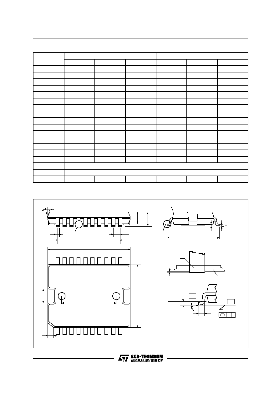
MULTIWATT15 PACKAGE MECHANICAL DATA
DIM.
mm
inch
MIN.
TYP.
MAX.
MIN.
TYP.
MAX.
A
5
0.197
B
2.65
0.104
C
1.6
0.063
D
1
0.039
E
0.49
0.55
0.019
0.022
F
0.66
0.75
0.026
0.030
G
1.02
1.27
1.52
0.040
0.050
0.060
G1
17.53
17.78
18.03
0.690
0.700
0.710
H1
19.6
0.772
H2
20.2
0.795
L
21.9
22.2
22.5
0.862
0.874
0.886
L1
21.7
22.1
22.5
0.854
0.870
0.886
L2
17.65
18.1
0.695
0.713
L3
17.25
17.5
17.75
0.679
0.689
0.699
L4
10.3
10.7
10.9
0.406
0.421
0.429
L7
2.65
2.9
0.104
0.114
M
4.25
4.55
4.85
0.167
0.179
0.191
M1
4.63
5.08
5.53
0.182
0.200
0.218
S
1.9
2.6
0.075
0.102
S1
1.9
2.6
0.075
0.102
Dia1
3.65
3.85
0.144
0.152
L9822E
8/11
e
a2
A
E
a1
PSO20MEC
DETAIL A
T
D
1
10
11
20
E1
E2
h x 45
∞
DETAIL A
lead
slug
a3
S
Gage Plane
0.35
L
DETAIL B
R
DETAIL B
(COPLANARITY)
G
C
- C -
SEATING PLANE
e3
b
c
N
N
PowerSO20 PACKAGE MECHANICAL DATA
DIM.
mm
inch
MIN.
TYP.
MAX.
MIN.
TYP.
MAX.
A
3.60
0.1417
a1
0.10
0.30
0.0039
0.0118
a2
3.30
0.1299
a3
0
0.10
0
0.0039
b
0.40
0.53
0.0157
0.0209
c
0.23
0.32
0.009
0.0126
D (1)
15.80
16.00
0.6220
0.6299
E
13.90
14.50
0.5472
0.570
e
1.27
0.050
e3
11.43
0.450
E1 (1)
10.90
11.10
0.4291
0.437
E2
2.90
0.1141
G
0
0.10
0
0.0039
h
1.10
0.0433
L
0.80
1.10
0.0314
0.0433
N
10
∞
(max.)
S
8
∞
(max.)
T
10.0
0.3937
(1) "D and F" do not include mold flash or protrusions
- Mold flash or protrusions shall not exceed 0.15mm (0.006")
L9822E
9/11
SO20 PACKAGE MECHANICAL DATA
DIM.
mm
inch
MIN
TYP
MAX
MIN
TYP
MAX
A
2.65
0.104
a1
0.1
0.2
0.004
0.008
a2
2.45
0.096
b
0.35
0.49
0.014
0.019
b1
0.23
0.32
0.009
0.013
C
0.5
0.020
c1
45
∞
(typ.)
D
1
12.6
0.039
0.496
E
10
10.65
0.394
0.419
e
1.27
0.050
e3
11.43
0.450
F
1
7.4
0.039
0.291
G
8.8
9.15
0.346
0.360
L
0.5
1.27
0.020
0.050
M
0.75
0.030
S
8
∞
(max.)
L9822E
10/11

Information furnished is believed to be accurate and reliable. However, SGS-THOMSON Microelectronics assumes no responsibility for
the consequences of use of such information nor for any infringement of patents or other rights of third parties which may result from its
use. No license is granted by implication or otherwise under any patent or patent rights of SGS-THOMSON Microelectronics. Specification
mentioned in this publication are subject to change without notice. This publication supersedes and replaces all information previously
supplied. SGS-THOMSON Microelectronics products are not authorized for use as critical components in life support devices or systems
without express written approval of SGS-THOMSON Microelectronics.
©
1996 SGS-THOMSON Microelectronics ≠ Printed in Italy ≠ All Rights Reserved
MULTIWATT
Æ
is a Registered Trademark of SGS-THOMSON Microelectronics
PowerSO-20
TM
is a Trademark of SGS-THOMSON Microelectronics
SGS-THOMSON Microelectronics GROUP OF COMPANIES
Australia - Brazil - Canada - China - France - Germany - Hong Kong - Italy - Japan - Korea - Malaysia - Malta - Morocco -
The Netherlands - Singapore - Spain - Sweden - Switzerland - Taiwan - Thailand - United Kingdom - U.S.A.
L9822E
11/11