LM137/LM237
LM337
March 1993
NEGATIVE VOLTAGE REGULATORS
THREE-TERMINAL ADJUSTABLE
.
OUTPUT VOLTAGE ADJUSTABLE DOWN TO
V
ref
.
1.5A GUARANTEED OUTPUT CURRENT
.
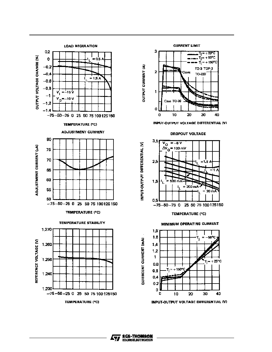
0.3%/V TYPICAL LOAD REGULATION
.
0.01%/V TYPICAL LINE REGULATION
.
CURRENT LIMIT CONSTANT WITH TEM-
PERATURE
.
RIPPLE REJECTION : 77dB
.
STANDARD 3-LEAD TRANSISTOR PACK-
AGES
.
EXCELLENT
THERMAL
REGULATION:
0.002%/V
.
50ppm/
∞
C TEMPERATURE COEFFICIENT
DESCRIPTION
The LM137 series are adjustable 3-terminal nega-
tive voltage regulators capable of supplying in ex-
cess - 1.5A over a - 1.2 to - 37V output voltage range.
They are exceptionally easy to use and require only
two external resistors to set the output voltage. Fur-
ther, both line and load regulation are better than
standard fixed regulators. Also, LM137 regulators
are supplied in standard transistor packages which
are easily mounted and handled. In addition to
higher performance than fixed regulators, the
LM137 series offer full overload protection available
only in integrated circuits. Included on the chip are
current limit, thermal overload protection and safe
area protection. All overload protection circuitry re-
mains fully functional even if the adjustment terminal
is disconnected.
TO-3
PIN CONNECTIONS
1 - Output
2 - Adj
Case is input
1 - Adj
2 - Output
3 - Input
Heatsink surface connected to input
TO-220
TO-3
(bottom view)
TO-39
(bottom view)
TO-220
(front view)
1 - Adj
2 - Output
3 - input
TO-39
1/14
ABSOLUTE MAXIMUM RATING
Symbol
Parameter
Value
Unit
V
I
- V
O
Input Output Voltage Differential
40
V
I
O
Output Current
TO-220/TO-3
1.5
A
TO-39
0.5
T
oper
LM137
-55 to 150
o
C
LM237
-25 to 150
LM337
0 to 125
T
stg
-65 to 150
o
C
P
tot
Internally Limited
W
THERMAL CHARACTERISTICS
Symbol
Parameter
Typ.
Max.
Unit
R
thj-case
Junction-case Thermal Resistance
TO-3
4
o
C/W
TO-220
3
TO-39
15
R
thj-amb
Junction-ambient Thermal Resistance
TO-3
35
o
C/W
TO-220
70
TO-39
160
ORDER CODES
PART NUMBER
TEMPERATURE
RANGE
PACKAGE
TO-3
TO-220
TO-39
LM137
-55 to 150
o
C
LM137K
LM137H
LM237
-25 to 150
o
C
LM237K
LM237SP
LM237H
LM337
0 to 125
o
C
LM337K
LM337SP
LM337H
LM137-LM237-LM337
2/14

ELECTRICAL CHARACTERISICS
LM137: -55
o
C < Tj < 150
o
C
LM237: -25
o
C < Tj < 150
o
C
LM337: 0
o
C < Tj < 150
o
C
V
I
- V
O
= 5V, I
O
= 0.5 A (unless otherwise specified)
Symbol
Parameter
LM137/LM237
LM337
Unit
Min.
Typ.
Max.
Min.
Typ.
Max.
V
ref
Reference Voltage
T
amb
= 25
o
C
T
min
T
j
T
max
3V
|V
I
- V
O
|
40V, 10mA
|I
O
|
|I
O(max)
|
P
P
max
-1.225
-1.2
-1.25
-1.25
-1.275
-1.3
-1.213
-1.2
-1.25
-1.25
-1.287
-1.3
V
K
VI
Line Regulation
(T
amb
= 25
o
C, 3V
|V
I
-V
O
|
40V) - Note 2
I
O
= 0.1 A
I
O
= 20 mA
0.01
0.01
0.02
0.02
0.01
0.01
0.04
0.04
%/V
%/V
K
VO
Load Regulation
(T
amb
= 25
o
C, 10mA
|I
O
|
|I
O(max)
|) - Note 2
|V
O
|
5V
|V
O
|
5V
15
0.3
25
0.5
15
0.3
50
1
mV
%
Thermal Regulation (T
amb
= 25
o
C, pulse 10 ms)
0.002
0.02
0.003
0.04
%/W
I
adj
Adjustment Pin Current
65
100
65
100
µ
A
I
adj
Adjustment Pin Current Change
(T
amb
= 25
o
C, 10mA
|I
O
|
|I
O(max)
|,
3V
|V
I
-V
O
|
40V)
2
5
2
5
µ
A
K
VI
Line Regulation (3V
|V
I
-V
O
|
40V) - Note 2
0.02
0.05
0.02
0.07
%/V
K
VO
Load Regulation
(10mA
|I
O
|
|I
O(max)
|) - Note 2
|V
O
|
5V
|V
O
|
5V
20
0.3
50
1
20
0.3
70
1.5
mV
%
|I
O(min)
|
Minimum Load Current
|V
I
-V
O
|
40V
|V
I
-V
O
|
10V
2.5
1.2
5
3
2.5
1.5
10
6
mA
mA
I
OS
Short Circuit Output Current
|V
I
-V
O
|
15V (TO-3 and TO-220)
|V
I
-V
O
|
15V (TO-39)
|V
I
-V
O
| = 40V, T
j
= 25
o
C (TO-3 and TO-220)
|V
I
-V
O
| = 40V, T
j
= 25
o
C (TO-39)
1.5
0.5
0.24
0.15
2.2
0.4
0.2
1.5
0.5
0.15
0.1
2.2
0.4
0.2
A
A
A
A
V
NO
RMS Output Noise (% of V
O
)
T
amb
= 25
o
C, 10Hz
f
10KHz
0.003
0.003
%
R
vf
Ripple Rejection Ratio
V
O
= - 10 V, f = 120 Hz
C
adj
= 10
µ
F
66
60
77
66
60
77
dB
dB
K
VT
Temperature Stability
0.6
0.6
%
K
VH
Long Term Stability (T
amb
= 125
o
C, 1000H)
0.3
1
0.3
1
%
Notes : 1. Although power dissipation is internally limited, these specifications are applicable for power dissipation of :
∑
2W for TO-39
∑
15W for TO-220
∑
20W for TO-3 Package
I
O( max)
is :
∑
1.5A for TO-3 and TO-220
∑
0.5A for TO-39
2. Regulation is measured at constant junction temperature, using pulse testing with a low duty cycle. Changes in out-
put voltage due to heating effects are covered under the specification for thermal regulation.
LM137-LM237-LM337
4/14