1/4
DATA BRIEFING
August 2003
Complete data available under NDA.
LRI64
Memory TAG IC, 64-bit Unique ID with WORM User Area
13.56MHz, ISO 15693 Standard Compliant
FEATURES SUMMARY
s
ISO15693 Compliant
s
13.56 MHz ±7 kHz Carrier Frequency
s
To the LRI64:
10% ASK modulation using 1/4 pulse position
coding (26 kbit/s)
s
From the LRI64:
Load modulation using Manchester coding with
423 kHz single subcarrier in fast data rate (26
kbit/s)
s
Internal Tuning Capacitor
s
7 x 8 bits WORM User Area
s
64-bit Unique Identifier (UID)
s
Kill Command
s
READ block and WRITE block (8-bit blocks)
s
2 ms Programming Time (typical)
s
More than 40 Year Data Retention
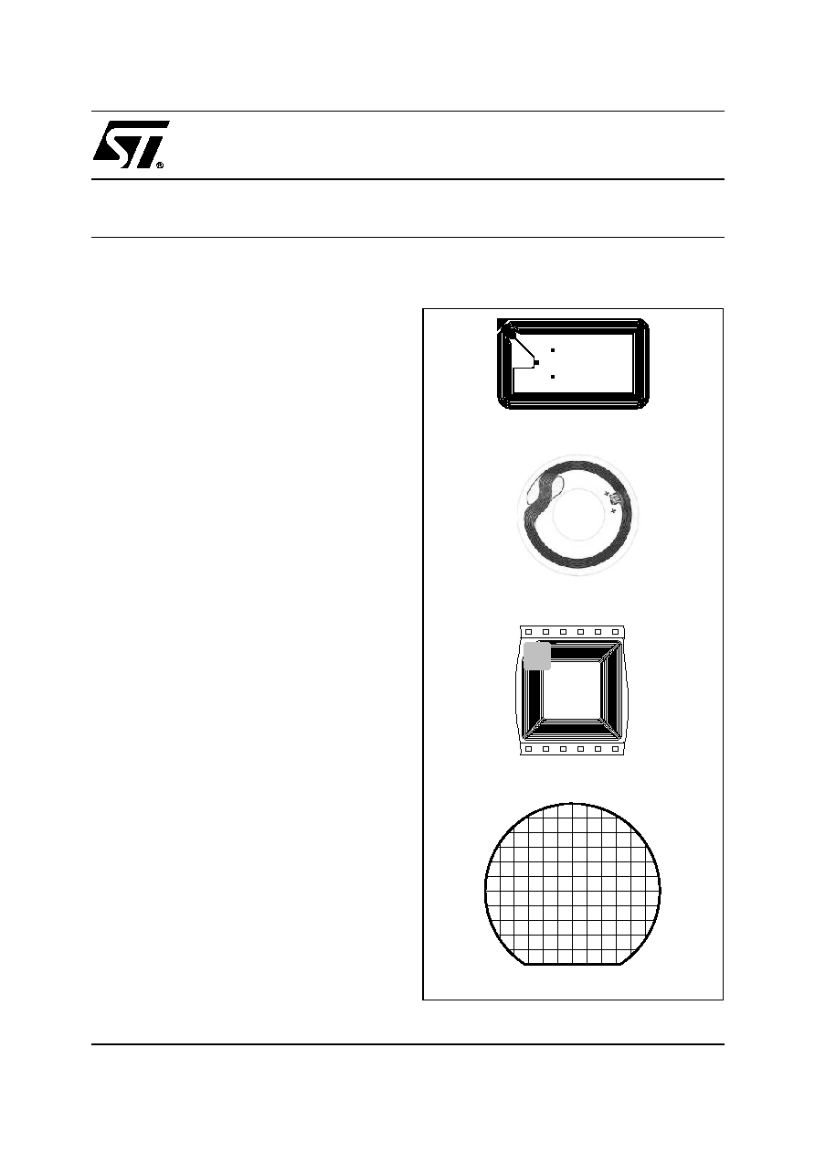
Figure 1. Delivery Forms
Wafer
Antenna (A1)
Antenna (C40)
Antenna (A6)
LRI64
2/4
SUMMARY DESCRIPTION
The LRI64 is a contactless memory, powered by
an externally transmitted radio wave. It contains a
120-bit non-volatile memory. The memory is orga-
nized as 15 blocks of 8 bits, of which 7 blocks are
accessible as Write-Once Read-Many (WORM)
memory.
The LRI64 is accessed using the 13.56MHz carri-
er. Incoming data are demodulated from the re-
ceived Amplitude Shift Keying (ASK) modulation
signal. The received ASK wave is 10% modulated.
The Data transfer rate from the reader to the
LRI64 is 26Kbit/s using the 1/4 pulse encoding
mode.
Outgoing data are sent by the LRI64, generated by
load variation using Manchester coding with a sin-
gle sub-carrier frequency of 423kHz. The Data
transfer rate from the LRI64 to the reader is
26Kbit/s in the fast data rate mode.
The LRI64 only supports the high data rate com-
munication protocols of the ISO15693 recommen-
dation. All other data rates and modulations are
not supported by the LRI64.
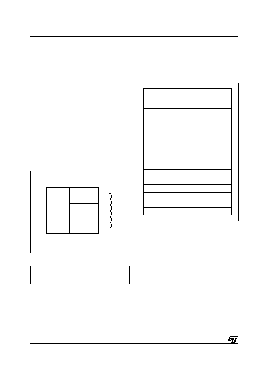
Figure 2. Logic Diagram
Table 1. Signal Names
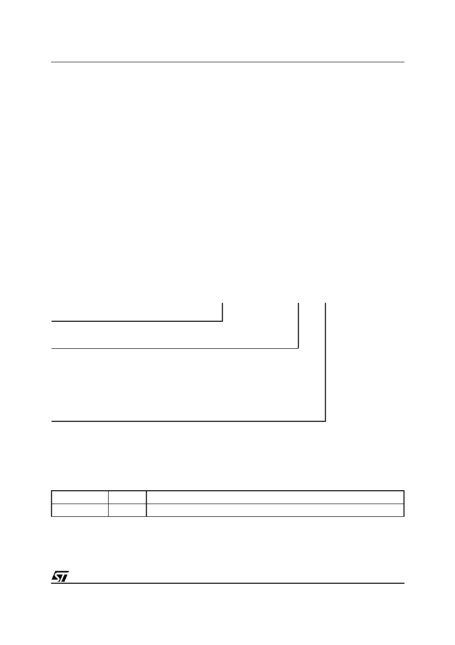
Memory Mapping
The LRI64 is organised as 15 blocks of 8 bits as
shown in Figure 3. Each block is automatically
write-protected after the first valid write access.
Figure 3. LRI64 Memory Mapping
The LRI64 uses the first 8 blocks (blocks 0 to 7) to
store the 64-bit Unique Identifier (UID) which are
writen by ST on the production line. Part of this
UID can be accessed and written by customers,
on special request. The UID is used during the
anti-collision sequence (INVENTORY).
The LRI64 has an AFI register, in which to store
the Application Family Identifier value, which is
used during the anti-collision sequence.
The LRI64 has a DSFID register, in which to store
the Data Storage Format Identifier value, which is
provided in the LRI64 INVENTORY answer.
The 5 following blocks (blocks 10 to 14) are Write-
Once Read-Many (WORM) memory. It is possible
to write to each of them once. After the first valid
write access, the block is automatically locked,
and only read commands are authorized.
AC1
Antenna Coil
AC0
Antenna Coil
AI08590
AC1
LRI64
AC0
Power
Supply
Regulator
Manchester
Load
Modulator
ASK
Demodulator
120-bit
WORM
Memory
Block
Addr
0
1
2
3
4
5
6
7
0
UID 0
1
UID 1
2
UID 2
3
UID 3
4
UID 4
5
UID 5
6
UID 6
7
UID 7
8
AFI (WORM)
9
DSFID (WORM)
10
WORM Area
11
WORM Area
12
WORM Area
13
WORM Area
14
WORM Area
3/4
LRI64
Commands
The LRI64 supports the following commands:
≠
INVENTORY
: used to perform the anti-collision
sequence. The LRI64 answers to the INVEN-
TORY command when all of the 64 bits of the
UID have been correctly written.
≠
STAY QUIET:
to put the LRI64 in quiet mode. In
this mode, the LRI64 only responds to com-
mands in addressed mode.
≠
READ BLOCK:
to output the 8 bits of the select-
ed block.
≠
WRITE BLOCK:
to write the 8-bit value in the
selected block, provided that it is not locked.
This command can be issued only once to each
block
≠
GET_SYSTEM_INFO:
to allow the application
system to identify the product. It gives the LRI64
memory size and IC reference (IC_ID).
≠
KILL:
to put the LRI64 in Killed mode. After a
valid KILL command, the LRI64 will no longer
answer to any commands.
Initial Dialogue for Vicinity Cards
The dialogue between the Vicinity Coupling De-
vice (VCD) and the Vicinity Integrated Circuit Card
(LRI64) is conducted through the following con-
secutive operations:
≠ activation of the LRI64 by the RF operating field
of the VCD.
≠ transmission of a command by the VCD.
≠ transmission of a response by the LRI64.
These operations use the RF power transfer and
communication signal interface specified in the fol-
lowing paragraphs. This technique is called Read-
er Talk First (RTF).
PART NUMBERING
For a list of available options (speed, package,
etc.) or for further information on any aspect of this
device, please contact your nearest ST Sales Of-
fice, or send your enquiries to the following email
address:
memories.contactless@st.com
Table 2. Ordering Information Scheme
REVISION HISTORY
Table 3. Document Revision History
Example:
LRI64
≠
W4
/ XXX
Device Type
LRI64
Package
W4 =180
µ
m ± 15
µ
m Unsawn Wafer, 18.5 pF tuning capacitor
SBN18= 180µm ± 15 µm Bumped and Sawn Wafer on 8-inch Frame
A1T= 45mm x 76mm Copper Antenna on Continuous Tape
A1S= 45mm x 76mm Copper Singulated Adhesive Antenna on Tape
A6S= 35mm Copper Singulated Adhesive CD Antenna on Tape
C40= 28mm x 28mm Micromodule Antenna on Super 35mm tape
Customer Code
XXX = Given by STMicroelectronics
Date
Version
Revision Details
27-Aug-2003
1.0
First Issue

LRI64
4/4
Information furnished is believed to be accurate and reliable. However, STMicroelectronics assumes no responsibility for the consequences
of use of such information nor for any infringement of patents or other rights of third parties which may result from its use. No license is granted
by implication or otherwise under any patent or patent rights of STMicroelectronics. Specifications mentioned in this publication are subject
to change without notice. This publication supersedes and replaces all information previously supplied. STMicroelectronics products are not
authorized for use as critical components in life support devices or systems without express written approval of STMicroelectronics.
The ST logo is registered trademark of STMicroelectronics
All other names are the property of their respective owners
© 2003 STMicroelectronics - All Rights Reserved
STMicroelectronics group of companies
Australia - Brazil - Canada - China - Finland - France - Germany - Hong Kong -
India - Israel - Italy - Japan - Malaysia - Malta - Morocco - Singapore - Spain - Sweden - Switzerland - United Kingdom - United States.
www.st.com