 | –≠–ª–µ–∫—Ç—Ä–æ–Ω–Ω—ã–π –∫–æ–º–ø–æ–Ω–µ–Ω—Ç: M20 | –°–∫–∞—á–∞—Ç—å:  PDF PDF  ZIP ZIP |

Preliminary Data
This is preliminary information on a new product now in development or undergoing evaluation. Details are subject to
change without notice.
October 2006
Rev 6
1/17
1
STLM20
Ultra-low Current 2.4V precision analog temperature sensor
Feature summary
Precision analog voltage output temperature
sensor
±1.5∞C temperature accuracy at 25∞C
Ultra-low quiescent supply current: 8.0µA
(max)
Operating voltage range: 2.4V to 5.5V
Operating temperature range:
≠55∞C to 130∞C (grade - 7)
≠40∞C to 85∞C (grade - 9)
SOT323-5 (SC70-5) 5-lead package
UDFN 4-lead package
Applications
Third generation (3G) cell phones
Multimedia PDA devices
GPS devices
Portable medical instruments
Voltage-controlled crystal oscillator
temperature monitors
RF Power transistor monitor
SOT323-5, SC70-5 (W8)
UDFN 4 Lead (DD)
www.st.com

Contents
STLM20
2/17
Contents
1
Summary description . . . . . . . . . . . . . . . . . . . . . . . . . . . . . . . . . . . . . . . 5
2
Transfer function . . . . . . . . . . . . . . . . . . . . . . . . . . . . . . . . . . . . . . . . . . . . 7
3
Maximum rating . . . . . . . . . . . . . . . . . . . . . . . . . . . . . . . . . . . . . . . . . . . . . 9
4
DC and AC characteristics . . . . . . . . . . . . . . . . . . . . . . . . . . . . . . . . . . . 10
5
Capacitive load . . . . . . . . . . . . . . . . . . . . . . . . . . . . . . . . . . . . . . . . . . . . 11
6
Typical operating characteristics . . . . . . . . . . . . . . . . . . . . . . . . . . . . . 12
7
Package mechanical . . . . . . . . . . . . . . . . . . . . . . . . . . . . . . . . . . . . . . . . 13
8
Part numbering . . . . . . . . . . . . . . . . . . . . . . . . . . . . . . . . . . . . . . . . . . . . 15
9
Revision history . . . . . . . . . . . . . . . . . . . . . . . . . . . . . . . . . . . . . . . . . . . 16

STLM20
List of tables
3/17
List of tables
Table 1.
Signal names . . . . . . . . . . . . . . . . . . . . . . . . . . . . . . . . . . . . . . . . . . . . . . . . . . . . . . . . . . . . 5
Table 2.
First order equations optimized for different temperature ranges . . . . . . . . . . . . . . . . . . . . . 7
Table 3.
Quadratic output equation (V
CC
= 2.7V) . . . . . . . . . . . . . . . . . . . . . . . . . . . . . . . . . . . . . . . . 8
Table 4.
Quadratic output equation for operations over the whole voltage range
(V
CC
= 2.4V to 5.5V) . . . . . . . . . . . . . . . . . . . . . . . . . . . . . . . . . . . . . . . . . . . . . . . . . . . . . . . 8
Table 5.
Absolute maximum ratings . . . . . . . . . . . . . . . . . . . . . . . . . . . . . . . . . . . . . . . . . . . . . . . . . . 9
Table 6.
DC and AC characteristics . . . . . . . . . . . . . . . . . . . . . . . . . . . . . . . . . . . . . . . . . . . . . . . . . 10
Table 7.
Resistor/capacitor combinations for the filter network . . . . . . . . . . . . . . . . . . . . . . . . . . . . 11
Table 8.
SOT323-5 ≠ 5-lead small outline transistor package mechanical data. . . . . . . . . . . . . . . . 13
Table 9.
UDFN - 4 lead mechanical data . . . . . . . . . . . . . . . . . . . . . . . . . . . . . . . . . . . . . . . . . . . . . 14
Table 10.
Ordering information scheme . . . . . . . . . . . . . . . . . . . . . . . . . . . . . . . . . . . . . . . . . . . . . . . 15
Table 11.
Marking description. . . . . . . . . . . . . . . . . . . . . . . . . . . . . . . . . . . . . . . . . . . . . . . . . . . . . . . 15
Table 12.
Revision history . . . . . . . . . . . . . . . . . . . . . . . . . . . . . . . . . . . . . . . . . . . . . . . . . . . . . . . . . 16

List of figures
STLM20
4/17
List of figures
Figure 1.
Logic diagram . . . . . . . . . . . . . . . . . . . . . . . . . . . . . . . . . . . . . . . . . . . . . . . . . . . . . . . . . . . . 5
Figure 2.
Connections (top view) . . . . . . . . . . . . . . . . . . . . . . . . . . . . . . . . . . . . . . . . . . . . . . . . . . . . . 6
Figure 3.
Filter network for noisy environments or capacitive loads > 300pF . . . . . . . . . . . . . . . . . . 11
Figure 4.
V
OUT
vs. Temperature . . . . . . . . . . . . . . . . . . . . . . . . . . . . . . . . . . . . . . . . . . . . . . . . . . . . 12
Figure 5.
SOT323-5 ≠ 5-lead small outline transistor package outline . . . . . . . . . . . . . . . . . . . . . . . 13
Figure 6.
UDFN ≠ 4-lead package outline . . . . . . . . . . . . . . . . . . . . . . . . . . . . . . . . . . . . . . . . . . . . . 14
STLM20
Summary description
5/17
1
Summary description
The STLM20 is a precision analog output temperature sensor for low current applications
where maximizing battery life is important. It operates over a ≠55∞C to 130∞C (grade 7) or
≠40∞C to 85∞C (grade 9) temperature range. The power supply operating range is 2.4V to
5.5V. The accuracy of the STLM20 is ± 1.5∞C, at an ambient temperature of 25∞C. The
temperature error increases linearly and reaches a maximum of ±2.5∞C at the temperature
range extremes. The temperature range is affected by the power supply voltage. For the
temperature grade 7 device, a power supply voltage of 2.7V to 5.5V, the temperature range
extremes are +130∞C and ≠55∞C. Decreasing the power supply voltage to 2.4V changes the
negative extreme to ≠30∞C, while the positive remains at +130∞C.
The STLM20 has a maximum quiescent supply current of 8µA. Therefore, self-heating is
negligible.
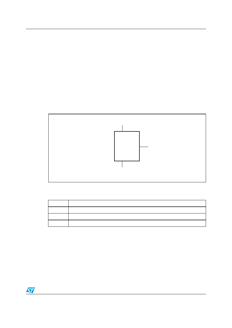
Figure 1.
Logic diagram
1.
Pin 2 GND may be grounded or left floating (SC70-5 only). For optimum thermal conductivity to the PC
board ground plane, it should be grounded.
Table 1.
Signal names
V
CC
Supply voltage
GND
Ground
V
OUT
Output voltage
NC
No connect
AI12252
VCC
STLM20
GND
(1)
VOUT