1/20
March 2004
M40Z300AV
3V NVRAM Supervisor for Up to 8 LPSRAMs
FEATURES SUMMARY
CONVERTS LOW POWER SRAM INTO
NVRAMs
PRECISION POWER MONITORING AND
POWER SWITCHING CIRCUITRY
AUTOMATIC WRITE-PROTECTION WHEN
V
CC
IS OUT-OF-TOLERANCE
TWO-INPUT DECODER ALLOWS
CONTROL FOR UP TO 8 SRAMs (with 2
devices active in parallel)
SUPPLY VOLTAGE AND POWER-FAIL
DESELECT VOLTAGE:
≠
M40Z300AV:
V
CC
= 3.0V to 3.6V
THS = V
SS
: 2.8V
V
PFD
3.0V
RESET OUTPUT (RST) FOR POWER ON
RESET
BATTERY LOW PIN (BL)
LESS THAN 20ns CHIP ENABLE ACCESS
PROPAGATION DELAY
PACKAGING INCLUDES A 16-LEAD SOIC
OR A 28-LEAD SOIC AND SNAPHAT
Æ
TOP
(to be ordered separately)
SOIC PACKAGE PROVIDES DIRECT
CONNECTION FOR A SNAPHAT TOP
WHICH CONTAINS THE BATTERY
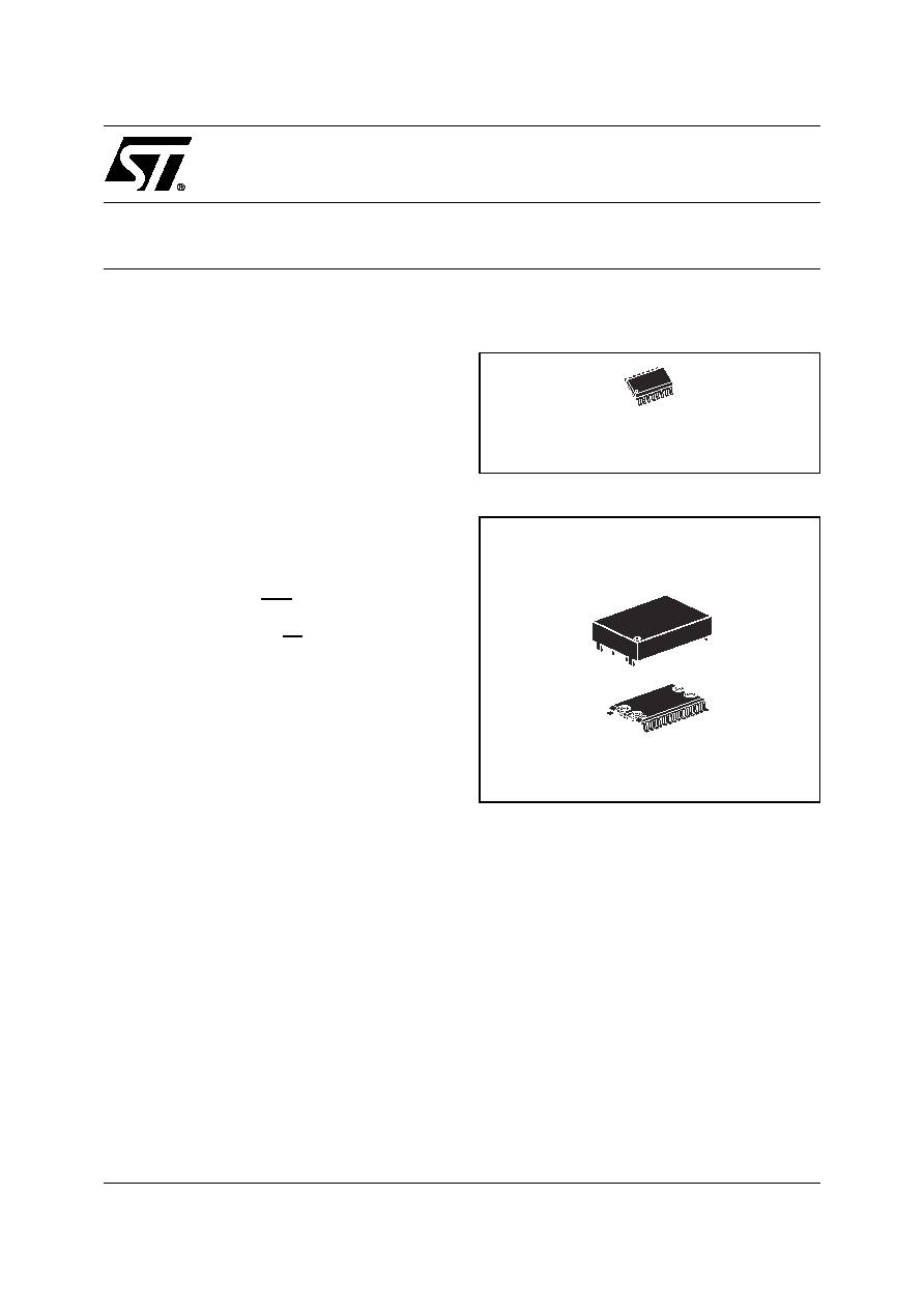
Figure 1. 16-pin SOIC Package
Figure 2. 28-pin SOIC Package*
16
1
SO16 (MQ)
28
1
SOH28 (MH)
SNAPHAT (SH)
Crystal/Battery

M40Z300AV
2/20
TABLE OF CONTENTS
FEATURES SUMMARY . . . . . . . . . . . . . . . . . . . . . . . . . . . . . . . . . . . . . . . . . . . . . . . . . . . . . . . . . . . . . 1
Figure 1. 16-pin SOIC Package . . . . . . . . . . . . . . . . . . . . . . . . . . . . . . . . . . . . . . . . . . . . . . . . . . . . 1
Figure 2. 28-pin SOIC Package*. . . . . . . . . . . . . . . . . . . . . . . . . . . . . . . . . . . . . . . . . . . . . . . . . . . . 1
DESCRIPTION . . . . . . . . . . . . . . . . . . . . . . . . . . . . . . . . . . . . . . . . . . . . . . . . . . . . . . . . . . . . . . . . . . . . 4
Figure 3. Logic Diagram . . . . . . . . . . . . . . . . . . . . . . . . . . . . . . . . . . . . . . . . . . . . . . . . . . . . . . . . . . 4
Table 1. Signal Names . . . . . . . . . . . . . . . . . . . . . . . . . . . . . . . . . . . . . . . . . . . . . . . . . . . . . . . . . . 4
Figure 4. 28-pin SOIC Connections . . . . . . . . . . . . . . . . . . . . . . . . . . . . . . . . . . . . . . . . . . . . . . . . . 5
Figure 5. M40Z300AV 16-pin SOIC Connections . . . . . . . . . . . . . . . . . . . . . . . . . . . . . . . . . . . . . . . 5
Figure 6. Hardware Hookup . . . . . . . . . . . . . . . . . . . . . . . . . . . . . . . . . . . . . . . . . . . . . . . . . . . . . . . 5
OPERATION . . . . . . . . . . . . . . . . . . . . . . . . . . . . . . . . . . . . . . . . . . . . . . . . . . . . . . . . . . . . . . . . . . . . . . 6
Two to Four Decode . . . . . . . . . . . . . . . . . . . . . . . . . . . . . . . . . . . . . . . . . . . . . . . . . . . . . . . . . . . . 6
Table 2. Truth Table . . . . . . . . . . . . . . . . . . . . . . . . . . . . . . . . . . . . . . . . . . . . . . . . . . . . . . . . . . . . 6
Figure 7. Address-Decode Time . . . . . . . . . . . . . . . . . . . . . . . . . . . . . . . . . . . . . . . . . . . . . . . . . . . . 6
Data Retention Lifetime Calculation . . . . . . . . . . . . . . . . . . . . . . . . . . . . . . . . . . . . . . . . . . . . . . . 7
Power-on Reset Output. . . . . . . . . . . . . . . . . . . . . . . . . . . . . . . . . . . . . . . . . . . . . . . . . . . . . . . . . . 7
Battery Low Pin . . . . . . . . . . . . . . . . . . . . . . . . . . . . . . . . . . . . . . . . . . . . . . . . . . . . . . . . . . . . . . . . 7
V
CC
Noise And Negative Going Transients. . . . . . . . . . . . . . . . . . . . . . . . . . . . . . . . . . . . . . . . . . 8
Figure 8. Supply Voltage Protection . . . . . . . . . . . . . . . . . . . . . . . . . . . . . . . . . . . . . . . . . . . . . . . . . 8
MAXIMUM RATING. . . . . . . . . . . . . . . . . . . . . . . . . . . . . . . . . . . . . . . . . . . . . . . . . . . . . . . . . . . . . . . . . 9
Table 3. Absolute Maximum Ratings . . . . . . . . . . . . . . . . . . . . . . . . . . . . . . . . . . . . . . . . . . . . . . . . 9
DC AND AC PARAMETERS. . . . . . . . . . . . . . . . . . . . . . . . . . . . . . . . . . . . . . . . . . . . . . . . . . . . . . . . . 10
Table 4. DC and AC Measurement Conditions . . . . . . . . . . . . . . . . . . . . . . . . . . . . . . . . . . . . . . . 10
Figure 9. AC Testing Load Circuit. . . . . . . . . . . . . . . . . . . . . . . . . . . . . . . . . . . . . . . . . . . . . . . . . . 10
Table 5. Capacitance. . . . . . . . . . . . . . . . . . . . . . . . . . . . . . . . . . . . . . . . . . . . . . . . . . . . . . . . . . . 10
Table 6. DC Characteristics. . . . . . . . . . . . . . . . . . . . . . . . . . . . . . . . . . . . . . . . . . . . . . . . . . . . . . 11
Figure 10.Power Down Timing . . . . . . . . . . . . . . . . . . . . . . . . . . . . . . . . . . . . . . . . . . . . . . . . . . . . 12
Figure 11.Power Up Timing . . . . . . . . . . . . . . . . . . . . . . . . . . . . . . . . . . . . . . . . . . . . . . . . . . . . . . . 12
Table 7. Power Down/Up Mode AC Characteristics . . . . . . . . . . . . . . . . . . . . . . . . . . . . . . . . . . . 13
PACKAGE MECHANICAL INFORMATION . . . . . . . . . . . . . . . . . . . . . . . . . . . . . . . . . . . . . . . . . . . . . 14
Figure 12.SOH28 ≠ 28-lead Plastic Small Outline, 4-socket battery SNAPHAT, Package Outline. 14
Table 8. SOH28 ≠ 28-lead Plastic Small Outline, battery SNAPHAT, Package Mechanical Data 14
Figure 13.SH ≠ 4-pin SNAPHAT Housing for 48mAh Battery, Package Outline . . . . . . . . . . . . . . . 15
Table 9. SH ≠ 4-pin SNAPHAT Housing for 48mAh Battery, Package Mechanical Data . . . . . . . 15
Figure 14.SH ≠ 4-pin SNAPHAT Housing for 120mAh Battery, Package Outline . . . . . . . . . . . . . . 16
Table 10. SH ≠ 4-pin SNAPHAT Housing for 120mAh Battery, Package Mechanical Data . . . . . . 16
Figure 15.SO16 ≠ 16-lead Plastic Small Outline, 150 mils body width, Package Outline . . . . . . . . 17
Table 11. SO16 ≠ 16-lead Plastic Small Outline, 150 mils body width, Package Mechanical Data 17
M40Z300AV
4/20
DESCRIPTION
The M40Z300AV NVRAM SUPERVISOR is a self-
contained device which converts a standard low-
power SRAM into a non-volatile memory. A preci-
sion voltage reference and comparator monitors
the V
CC
input for an out-of-tolerance condition.
When an invalid V
CC
condition occurs, the condi-
tioned chip enable outputs (E1
CON
to E4
CON
) are
forced inactive to write-protect the stored data in
the SRAM. During a power failure, the SRAM is
switched from the V
CC
pin to the lithium cell within
the SNAPHAT
Æ
to provide the energy required for
data retention. On a subsequent power-up, the
SRAM remains write protected until a valid power
condition returns.
The 28-pin, 330mil SOIC provides sockets with
gold plated contacts for direct connection to a sep-
arate SNAPHAT housing containing the battery.
The SNAPHAT housing has gold plated pins
which mate with the sockets, ensuring reliable
connection. The housing is keyed to prevent im-
proper insertion. This unique design allows the
SNAPHAT battery package to be mounted on top
of the SOIC package after the completion of the
surface mount process which greatly reduces the
board manufacturing process complexity of either
directly soldering or inserting a battery into a sol-
dered holder. Providing non-volatility becomes a
"SNAP." The 16-pin SOIC provides battery pins for
an external user-supplied battery.
Insertion of the SNAPHAT housing after reflow
prevents potential battery damage due to the high
temperatures required for device surface-mount-
ing. The SNAPHAT housing is also keyed to pre-
vent reverse insertion.
The 28-pin SOIC and battery packages are
shipped separately in plastic anti-static tubes or in
Tape & Reel form. For the 28-lead SOIC, the bat-
tery/crystal package (e.g., SNAPHAT) part num-
ber is "M4ZXX-BR00SH" (see
Table
13., page 18
).
Caution: Do not place the SNAPHAT battery top
in conductive foam, as this will drain the lithium
button-cell battery.
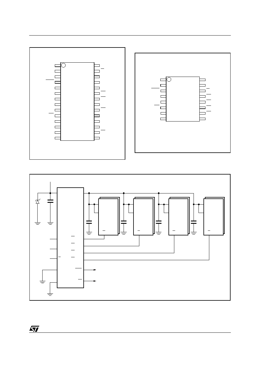
Figure 3. Logic Diagram
Note: 1. For 16-pin SOIC package only.
2. THS pin must be connected to V
SS
.
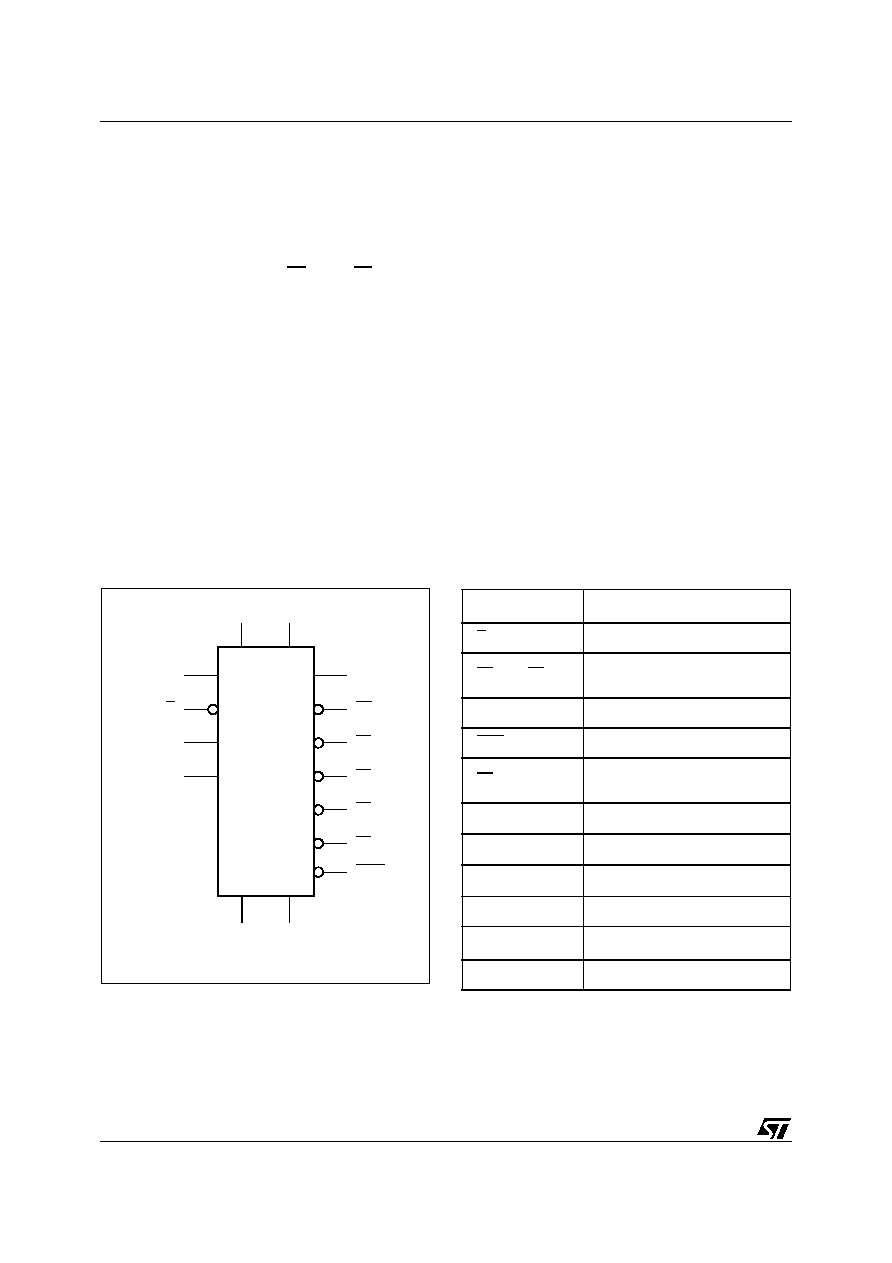
Table 1. Signal Names
Note: 1. THS pin must be connected to V
SS
.
2. For M40Z300AV, B≠ must be connected to the negative
battery terminal only (not to Pin 8, V
SS
).
AI08893
THS
(2)
VCC
M40Z300AV
BL
VSS
E
VOUT
B
A
E1CON
E2CON
E3CON
E4CON
RST
B+
(1)
B≠
(1)
THS
(1)
Threshold Select Input
E
Chip Enable Input
E1
CON
- E4
CON
Conditioned Chip Enable
Output
A, B
Decoder Inputs
RST
Reset Output (Open Drain)
BL
Battery Low Output (Open
Drain)
V
OUT
Supply Voltage Output
V
CC
Supply Voltage
V
SS
Ground
B +
Positive Battery Pin
B ≠
(2)
Negative Battery Pin
NC
Not Connected Internally