1/14
PRELIMINARY DATA
September 2004
This is preliminary information on a new product now in development or undergoing evaluation. Details are subject to change without notice.
M41T56C64
512 bit (64 bit x8) Serial Access
TIMEKEEPER
Æ
SRAM + 64 Kbit (8192 bit x8) EEPROM
FEATURES SUMMARY
5V ±10% SUPPLY VOLTAGE
I
2
C BUS COMPATIBLE
OPERATING TEMPERATURE OF ≠40 TO
85∞C
PACKAGING INCLUDES:
≠
18-lead SOIC (with Embedded Crystal)
Serial RTC Features
COUNTERS FOR SECONDS, MINUTES,
HOURS, DAY, DATE, MONTH, YEARS, AND
CENTURY
EMBEDDED CRYSTAL PACKAGE
SOFTWARE CLOCK CALIBRATION
AUTOMATIC POWER-FAIL DETECT AND
SWITCH CIRCUITRY
56 BYTES OF GENERAL PURPOSE SRAM
ULTRA-LOW BATTERY SUPPLY CURRENT
OF 450nA
AUTOMATIC LEAP YEAR COMPENSATION
SPECIAL SOFTWARE PROGRAMMABLE
OUTPUT
TWO-WIRE I
2
C SERIAL INTERFACE
SUPPORTS 100kHz PROTOCOL
Serial EEPROM Features
8192 BYTES OF GENERAL PURPOSE
EEPROM (MORE THAN 1E6 ERASE/WRITE
CYCLES)
TWO-WIRE I
2
C SERIAL INTERFACE
SUPPORTS 400kHz PROTOCOL
BYTE AND PAGE WRITE (UP TO 32 BYTES)
MORE THAN 40 YEAR DATA RETENTION
SELF-TIMED PROGRAMMING CYCLE
Figure 1. Package
1
18
SOX18 (MY)
18-pin (300mil) SOIC
Embedded Crystal

M41T56C64
2/14
TABLE OF CONTENTS
FEATURES SUMMARY . . . . . . . . . . . . . . . . . . . . . . . . . . . . . . . . . . . . . . . . . . . . . . . . . . . . . . . . . . . . . 1
Serial RTC Features . . . . . . . . . . . . . . . . . . . . . . . . . . . . . . . . . . . . . . . . . . . . . . . . . . . . . . . . . . . . 1
Serial EEPROM Features . . . . . . . . . . . . . . . . . . . . . . . . . . . . . . . . . . . . . . . . . . . . . . . . . . . . . . . . 1
Figure 1. Package. . . . . . . . . . . . . . . . . . . . . . . . . . . . . . . . . . . . . . . . . . . . . . . . . . . . . . . . . . . . . . . 1
SUMMARY DESCRIPTION . . . . . . . . . . . . . . . . . . . . . . . . . . . . . . . . . . . . . . . . . . . . . . . . . . . . . . . . . . . 3
Calibration . . . . . . . . . . . . . . . . . . . . . . . . . . . . . . . . . . . . . . . . . . . . . . . . . . . . . . . . . . . . . . . . . . . . 3
Figure 2. Logic Diagram . . . . . . . . . . . . . . . . . . . . . . . . . . . . . . . . . . . . . . . . . . . . . . . . . . . . . . . . . . 3
Table 1. Signal Names . . . . . . . . . . . . . . . . . . . . . . . . . . . . . . . . . . . . . . . . . . . . . . . . . . . . . . . . . . 3
Figure 3. 18-pin SOIC Connections . . . . . . . . . . . . . . . . . . . . . . . . . . . . . . . . . . . . . . . . . . . . . . . . . 3
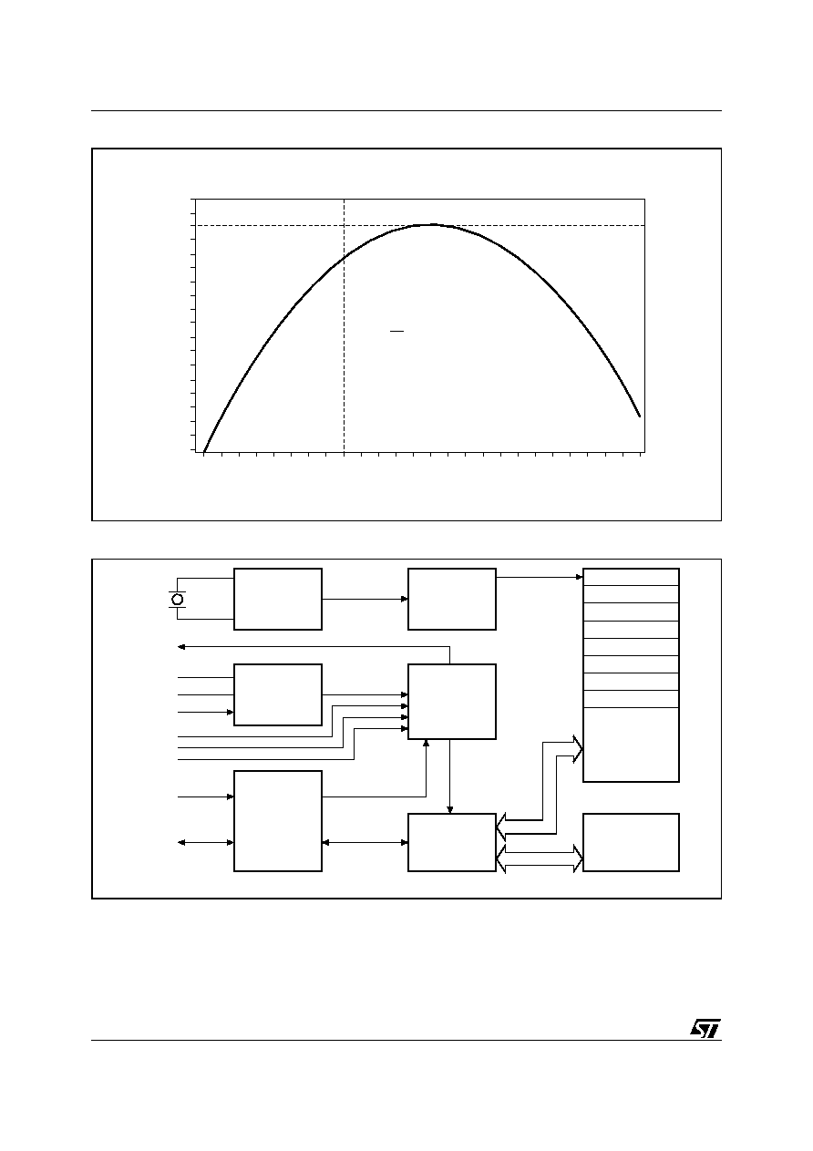
Figure 4. Crystal Accuracy Across Temperature . . . . . . . . . . . . . . . . . . . . . . . . . . . . . . . . . . . . . . . 4
Figure 5. Block Diagram . . . . . . . . . . . . . . . . . . . . . . . . . . . . . . . . . . . . . . . . . . . . . . . . . . . . . . . . . . 4
Table 2. Device Select Code . . . . . . . . . . . . . . . . . . . . . . . . . . . . . . . . . . . . . . . . . . . . . . . . . . . . . . 5
OPERATION . . . . . . . . . . . . . . . . . . . . . . . . . . . . . . . . . . . . . . . . . . . . . . . . . . . . . . . . . . . . . . . . . . . . . . 5
Serial RTC Device . . . . . . . . . . . . . . . . . . . . . . . . . . . . . . . . . . . . . . . . . . . . . . . . . . . . . . . . . . . . . . 5
EEPROM Device . . . . . . . . . . . . . . . . . . . . . . . . . . . . . . . . . . . . . . . . . . . . . . . . . . . . . . . . . . . . . . . 5
MAXIMUM RATING. . . . . . . . . . . . . . . . . . . . . . . . . . . . . . . . . . . . . . . . . . . . . . . . . . . . . . . . . . . . . . . . . 5
Table 3. Absolute Maximum Ratings . . . . . . . . . . . . . . . . . . . . . . . . . . . . . . . . . . . . . . . . . . . . . . . . 5
DC AND AC PARAMETERS. . . . . . . . . . . . . . . . . . . . . . . . . . . . . . . . . . . . . . . . . . . . . . . . . . . . . . . . . . 6
Table 4. Operating and AC Measurement Conditions . . . . . . . . . . . . . . . . . . . . . . . . . . . . . . . . . . . 6
Figure 6. AC Measurement I/O Waveform . . . . . . . . . . . . . . . . . . . . . . . . . . . . . . . . . . . . . . . . . . . . 6
Table 5. Capacitance and Input Parameters . . . . . . . . . . . . . . . . . . . . . . . . . . . . . . . . . . . . . . . . . . 6
Table 6. DC Characteristics. . . . . . . . . . . . . . . . . . . . . . . . . . . . . . . . . . . . . . . . . . . . . . . . . . . . . . . 7
Figure 7. Bus Timing Requirements Sequence (Serial RTC) . . . . . . . . . . . . . . . . . . . . . . . . . . . . . . 8
Table 7. AC Characteristics, (Serial RTC, M41T56) . . . . . . . . . . . . . . . . . . . . . . . . . . . . . . . . . . . . 8
Figure 8. AC Waveforms (Serial EEPROM) . . . . . . . . . . . . . . . . . . . . . . . . . . . . . . . . . . . . . . . . . . . 9
Table 8. AC Characteristics (Serial EEPROM, M24C64) . . . . . . . . . . . . . . . . . . . . . . . . . . . . . . . 10
PACKAGE MECHANICAL . . . . . . . . . . . . . . . . . . . . . . . . . . . . . . . . . . . . . . . . . . . . . . . . . . . . . . . . . . 11
Figure 9. SOX18 ≠ 18-lead Plastic Small Outline, 300mils, Embedded Crystal, Package Outline. 11
Table 9. SOX18 ≠ 18-lead Plastic Small Outline, 300mils, Embedded Crystal, Package Mech. . 11
PART NUMBERING . . . . . . . . . . . . . . . . . . . . . . . . . . . . . . . . . . . . . . . . . . . . . . . . . . . . . . . . . . . . . . . 12
Table 10. Ordering Information Scheme . . . . . . . . . . . . . . . . . . . . . . . . . . . . . . . . . . . . . . . . . . . . . 12
REVISION HISTORY. . . . . . . . . . . . . . . . . . . . . . . . . . . . . . . . . . . . . . . . . . . . . . . . . . . . . . . . . . . . . . . 13
Table 11. Document Revision History . . . . . . . . . . . . . . . . . . . . . . . . . . . . . . . . . . . . . . . . . . . . . . . 13

3/14
M41T56C64
SUMMARY DESCRIPTION
The M41T56C64 TIMEKEEPER
Æ
is a low power,
512- bit static CMOS RAM organized as 64 words
by 8 bits plus a 64Kb EEPROM. A built-in 32,768
Hz oscillator (crystal controlled) and the first 8
bytes of the RAM are used for the clock/calendar
function and are configured in binary coded deci-
mal (BCD) format. Addresses and data are trans-
ferred serially via a two-line, bi-directional bus.
The built-in address register is incremented auto-
matically after each WRITE or READ data byte.
The M41T56C64 clock has a built-in power sense
circuit which detects power failures and automati-
cally switches to the battery supply during power
failures. The energy needed to sustain the RAM
and clock operations can be supplied from a small
lithium coin cell.
Typical data retention time for the Serial RTC is in
excess of 10 years with a 50mAh, 3V lithium cell.
The M41T56C64 is supplied in an 18-lead Plastic
SOIC package.
Calibration
As the crystal is molded together with the silicon in
this package, ST can program the appropriate cal-
ibration value necessary to achieve ±6 ppm accu-
racy at 25∞C after two reflows (see
Figure
4., page 4
). This calibration value will be written
into address 1550h of the EEPROM. This clock
accuracy can then be guaranteed to drift no more
than ±4 ppm the first year, and ±2 ppm for each
following year due to crystal aging.
Figure 2. Logic Diagram
Note: 1. Open Drain output
Table 1. Signal Names
Figure 3. 18-pin SOIC Connections
Note: 1. Open Drain output
AI09123
V
CC
M41T56
+
M24C64
(EEPROM)
V
SS
SCL
E
0
E
1
E
2
WC
SDA
FT/OUT
(1)
V
BAT
FT/OUT
Frequency Test / Output Driver
(Open Drain)
SDA
Serial Data Address Input / Output
SCL
Serial Clock
WC
Write Control
E0, E1, E2
Chip Enables
V
BAT
Battery Supply Voltage
V
CC
Supply Voltage
V
SS
Ground
AI09124
8
2
3
4
5
6
7
9
12
11
10
18
17
16
15
14
13
1
WC
E1
NC
NC
NC
NC
NC
NC
V
SS
V
BAT
V
CC
E0
NC
E2
SDA
SCL
NC
FT/OUT
(1)
M41T56
+
M24C64
(EEPROM)

5/14
M41T56C64
Table 2. Device Select Code
Note: 1. The most significant bit, b7, is sent first.
2. E0, E1, and E2 are compared against the respective external pins on the memory device.
OPERATION
Serial RTC Device
The M41T56C64 contains one Serial RTC
(M41T56). For detailed information on how to use
the devices, see the M41T56 datasheet, which is
available from your local STMicroelectronics dis-
tributor or from the STMicroelectronics website, ht-
tp://www.st.com/rtc/.
EEPROM Device
The M41T56C64 contains a 64 Kbit Serial EE-
PROM (M24C64). For detailed information on how
to use the devices, see the M24C64 datasheet,
which is available from your local STMicroelec-
tronics distributor or from the STMicroelectronics
website, http://www.st.com/eeprom/.
MAXIMUM RATING
Stressing the device above the rating listed in the
"Absolute Maximum Ratings" table may cause
permanent damage to the device. These are
stress ratings only and operation of the device at
these or any other conditions above those indicat-
ed in the Operating sections of this specification is
not implied. Exposure to Absolute Maximum Rat-
ing conditions for extended periods may affect de-
vice reliability. Refer also to the
STMicroelectronics SURE Program and other rel-
evant quality documents.
Table 3. Absolute Maximum Ratings
Note: 1. For SOX18 package, Lead-free (Pb-free) lead finish: Reflow at peak temperature of 240∞C (total thermal budget not to exceed
180∞C for between 90 to 150 seconds).
CAUTION: Negative undershoots below ≠0.3V are not allowed on any pin while in the Battery Back-up mode.
Device Type Identifier
(1)
Chip Enable Address
(2)
RW
M24C64
b7
b6
b5
b4
b3
b2
b1
b0
1
0
1
0
E2
E1
E0
RW
M41T56
1
1
0
1
0
0
0
RW
Symbol
Parameter
Value
Unit
T
A
Ambient Operating Temperature
≠40 to 85
∞C
T
STG
Storage Temperature (V
CC
Off, Oscillator Off)
≠55 to 125
∞C
T
SLD
(1)
Lead Solder Temperature for 10 seconds
240
∞C
V
IO
Input or Output Voltages
≠0.3 to 6.5
V
V
CC
Supply Voltage
≠0.3 to 6.5
V
I
O
Output Current
20
mA
P
D
Power Dissipation
0.25
W