
TDA8160
INFRARED REMOTE CONTROL RECEIVER
August 1992
.
LOW SUPPLY VOLTAGE (V
S
= 5V)
.
LOW CURRENT CONSUMPTION (I
S
= 6mA)
.
INTERNAL 5.5 V SHUNT REGULATOR
.
PHOTODIODE DIRECTLY COUPLED WITH
THE I.C.
.
INPUT STAGE WITH GOOD REJECTION AT
LOW FREQUENCY
.
LARGE INPUT DYNAMIC RANGE
.
FEW EXTERNAL COMPONENTS
DIP8
(Plastic Package)
ORDER CODE : TDA 8160
1
2
3
4
8
7
6
5
OUTPUT
OPEN
SUPPLY
VOLTAGE
D1 DC BIAS
PEAK
DETECTOR
DECOUPLING
GROUND
INPUT
8160-01.EPS
PIN CONNECTIONS
DESCRIPTION
The TDA8160 is a monolithic integrated circuit
in-lead minidip plastic package specially designed
to amplify the infrared signals in remote controlled
TV, Radio or VCR sets. It can be used in flash
transmission mode in conjunction with dedicated
remote control circuits (for example : M491-494).
8160-02.EPS
BLOCK DIAGRAM
1/4
ABSOLUTE MAXIMUM RATINGS
Symbol
Parameter
Value
Unit
V
s
Supply Voltage
16
V
T
stg�j
Storage and Junction Temperature
� 40, +150
�
C
P
tot
Total Power Dissipation at T
amb
= 70
�
C
400
mW
8160-01.TBL
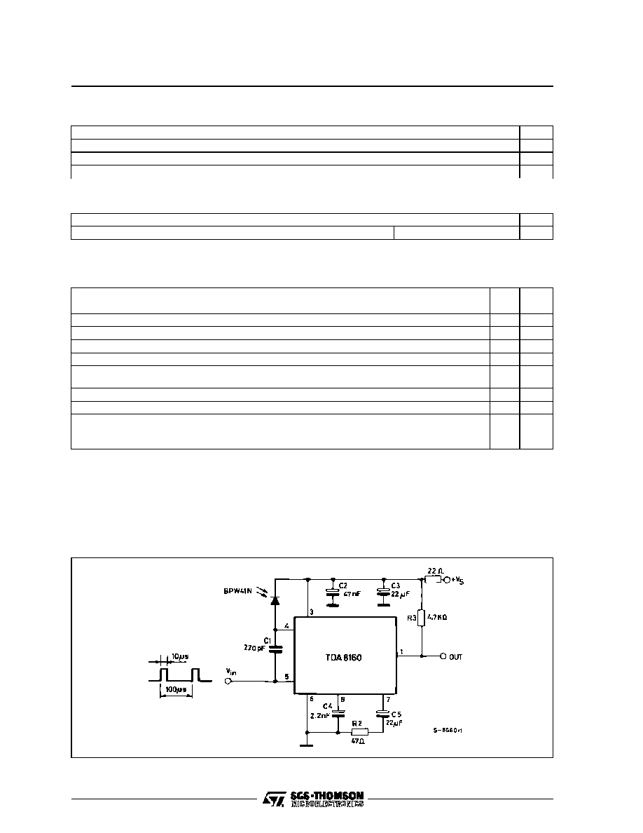
CIRCUIT DESCRIPTION (see the block diagram)
The infrared light received from D1 generates an
AC signal that comes in to the device at pin 5. The
capacitor C1 and the integrated 10k
resistor
(pin 4) filter out the low frequency noise.
The first stage shows a voltage gain of about 28dB ;
the second stage is a voltage to current converter
of 50mA/V (R
2
= Zero). A sensitive peak detector
detects the amplifier signal ; one open collector
output (pin 1) gives out the recovered pulses.
THERMAL DATA
Symbol
Parameter
Value
Unit
R
th (j-a)
Thermal Resistance Junction-ambient
Max
200
�
C/W
8160-02.TBL
ELECTRICAL CHARACTERISTICS
(Refer to the test circuit ; V
S
= 5V, f
O
= 10kHz, T
amb
= 25
o
C, unless otherwise specified)
Symbol
Parameter
Test Conditions
Min.
Typ.
Max.
Unit
V
S
Supply Voltage
Applied between Pins 3 and 6
4
5
5.25
V
I
S
Supply Current (Pin 3)
6
mA
V
3
Stabilized Voltage at Pin 3
I
3
= 8mA
5.5
V
G
V
1st
Voltage Gain (1st stage)
28
dB
g
m
2nd
Transconductance (2nd stage)
15
mA/V
V
IN
Input Voltage Sensitivity (Pin 5)
For Full Swing at the Output Pin 1
R
gen
= 600
2
mV
P
I
IN
Input Current Sensitivity (Pin 5)
For Full Swing at the Output Pin 1
10
nA
P
R
IN
Input Impedance
200
k
L
f
R
Low Frequency Rejection at the Input
Stage
C1 = 100pF , f = 100HZ
30
dB
N
Noise Signal at Pin 7
C4 Missing
200
mV
PP
8160-03.TBL
8160-03.EPS
TEST CIRCUIT
TDA8160
2/4

Information furnished is believed to be accurate and reliable. However, SGS-THOMSON Microelectronics assumes no responsibility
for the consequences of use of such information nor for any infringement of patents or other rights of third parties which may result
from its use. No licence is granted by implication or otherwise under any patent or patent rights of SGS-THOMSON Microelectronics.
Specifications mentioned in this publication are subject to change without noti ce. This publication supersedes and replaces all
information previously supplied. SGS-THOMSON Microelectronics products are not authorized for use as critical components in life
support devices or systems without express written approval of SGS-THOMSON Microelectronics.
�
1994 SGS-THOMSON Microelectronics - All Rights Reserved
Purchase of I
2
C Components of SGS-THOMSON Microelectronics, conveys a license under the Philips
I
2
C Patent. Rights to use these components in a I
2
C system, is granted provided that the system confo rms to
the I
2
C Standard Specifications as defined by Philips.
SGS-THOMSON Microelectronics GROUP OF COMPANIES
Australia - Brazil - China - France - Germany - Hong Kong - Italy - Japan - Korea - Malaysia - Malta - Morocco
The Netherlands - Singapore - Spain - Sweden - Switzerland - Taiwan - Thailand - United Kingdom - U.S.A.
8
1
4
I
a1
L
B
e
D
b
Z
e3
F
B1
E
5
Z
A
e4
b1
PM-DIP8.EPS
PACKAGE MECHANICAL DATA
8 PINS - PLASTIC DIP
Dimensions
Millimeters
Inches
Min.
Typ.
Max.
Min.
Typ.
Max.
A
3.32
0.131
a1
0.51
0.020
B
1.15
1.65
0.045
0.065
b
0.356
0.55
0.014
0.022
b1
0.204
0.304
0.008
0.012
D
10.92
0.430
E
7.95
9.75
0.313
0.384
e
2.54
0.100
e3
7.62
0.300
e4
7.62
0.300
F
6.6
0260
i
5.08
0.200
L
3.18
3.81
0.125
0.150
Z
1.52
0.060
DIP8.TBL
TDA8160
4/4
