 | –≠–ª–µ–∫—Ç—Ä–æ–Ω–Ω—ã–π –∫–æ–º–ø–æ–Ω–µ–Ω—Ç: TDA7361 | –°–∫–∞—á–∞—Ç—å:  PDF PDF  ZIP ZIP |
TDA7361
LOW VOLTAGE NBFM IF SYSTEM
June1993
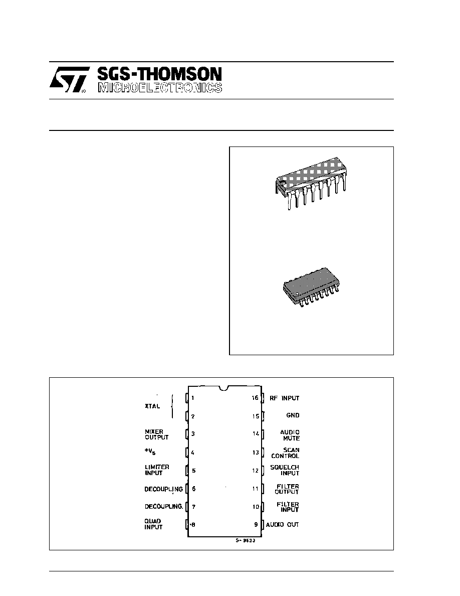
PIN CONNECTION
DIP16
ORDERING NUMBER : TDA7361
.
OPERATION FROM 1.8V TO 9V
.
LOW DRAIN CURRENT (4mA, V
s
= 4V)
.
HIGH SENSITIVITY
(-3dB input limiting at 3
µ
V)
.
8
µ
V INPUT FOR 20dB S/N
.
LOW EXTERNAL FAIR COUNT
DESCRIPTION
The TDA7361 is a low-power narrow band FM IF
demodulation system operable to less than 2 V
supply voltage.
The device includes Oscillator, Mixer, Limiting Am-
plifier, Quadrature Discriminato r, Op. Amp.
Squelch, Scan Control and Mute Switch.
The TDA7361 is designed for use in NBFM dual
conversion communication equipments using a
455 KHz ceramic filter like cordless telephones,
walkie-talkies, scan receivers, etc.
SO16
ORDERING NUMBER : TDA7361D
1/8

BLOCK DIAGRAM
Pin FUNCTION
No
Name
Function
1-2
XTAL OSCILLATOR
Connections for the Colpitts XTAL Oscillator.
The XTAL may be replaced by an inductor (see Figure 5) if the application
does not require high stability.
3
MIXER OUT
The Mixer is double balanced to reduce spurious products. The output
impedance is 1.8kW to match the input impedance of a 455kHz ceramic filter.
4
SUPPLY VOLTAGE
Must be well decoupled with a 100nF ceramic capacitor.
5
IF LIMITER INPUT
Input pin of the six stages amplifier with about 50
µ
V limiting sensitivity and
1.8k
input impedance. The if output is connected to the external quadrature
coil (Pin 8) via an internal 10pF capacitor.
6-7
DECOUPLING
Good quality 100nF ceramic capacitors and a suitable layou are important.
8
QUADRATURE COIL
A quadrature detector is uded to demodulate the 455kHz FM signal. The Q of
the quad coil has direct effect on output level and distorsion (see Figure 6).
For proper operation the voltage should be 100mV
RMS
.
9
AUDIO OUTPUT SIGNAL
The audio output signal is buffered by an internal emitter follower.
10
OPERATIONAL
AMPLIFIER INPUT
Because of the low DC bias, the swing on the operational amplifier output is
limited to 500mV
RMS
.
11
OPERATIONAL
AMPLIFIER OUTPUT
This can be increased by adding a resistor from the operational amplifier input
to ground.
12
SQUELCH INPUT
The squelch trigger circuit with a low bias on the input (Pin 12) will force Pin
13 high ; and Pin 14 low.
13
SCAN CONTROL
Pulling Pin 12 above mute threshold (0.65V) will force Pin 13 to an impedance
of about 60k
to ground and Pin 14 will be an open circuit.
14
MUTE
An hysteresis of about 50mV at Pin 12 will effectively prevent jitter.
15
GND
Ground Connection
16
10.7MHz MIXER INPUT
Input of the Wide-band Mixer. Normally used as 10MHz/455kHz converter, it
can be also used with input frequencies up to 60MHz.
TDA7361
2/8
ABSOLUTE MAXIMUM RATINGS
Symbol
Parameter
Value
Unit
V
S
Supply Voltage
9
V
V
I
RF Input Voltage (Pin 16)
1
V
RMS
V
8
Detector Input Voltage
1
V
PP
V
14
Mute Function Voltage
- 0.5 to +5
V
T
oper
Operating Ambient Temperature
0 to 70
o
C
T
stg
Storage Temperature
- 65, + 150
o
C
THERMAL DATA
Symbol
Parameter
SO16
DIP16
Unit
R
th j-amb
Junction-ambient Thermal Resistance
Max.
200
100
o
C/W
ELECTRICAL CHARACTERISTICS
T
amb
= 25
o
C, unless otherwise specified
Symbol
Parameter
Test Conditions
Min.
Typ.
Max.
Unit
V
S
Supply Voltage Range
1.8
4
9
V
I
S
Supply Current
Squelch OFF
Squelch ON
3.8
4.7
mA
mA
V
I
Input Quieting Voltage
S/N = 20dB
8
µ
V
V
I
Input Limiting Voltage
- 3dB limiting
3
µ
V
V
O
Recovered Audio Output
V
I
= 10mV
150
mV
RMS
V
9
Detector Output Voltage
1.5
V
DC
R
9
Detector Output Impedance
400
Dtectot Center Frequency Slope
150
mV/kHz
G
V
Operational Amplifier Gain
f = 10kHz, G
V
= V
11
/V
10
40
55
dB
V
11
Operational Amplifier Output Voltage
1.5
V
DC
I
B
Operational Amplifier Input Bias Current
Pin 10
20
nA
V
T
Trigger Hysteresis
50
mV
R
m
Mute Switching Impedance
Low
High
50
10
M
V
13
Scan Voltage
Pin 12 High (2V)
Pin 12 Low (0V)
3.0
0
3.4
0.5
V
DC
V
DC
G
C
Mixer Converter Gain
30
dB
R
I
Input Resistance
3.3
k
C
I
Input Capacitance
2.2
pF
TDA7361
3/8

Figure 2 : Test Circuit
Figure 3 : Supply Current versus Supply Voltage
Figure 4 : FM IF Characteristics
TDA7361
4/8

Figure 6 : Effect of Quadrature Coil "Q" on Audio
Level and Distortion
Figure 5 : Colpitts XTAL Oscillator
Figure 7 : Application Information (49MHz cordless receiver)
TDA7361
5/8