 | –≠–ª–µ–∫—Ç—Ä–æ–Ω–Ω—ã–π –∫–æ–º–ø–æ–Ω–µ–Ω—Ç: HV256X | –°–∫–∞—á–∞—Ç—å:  PDF PDF  ZIP ZIP |

32-Channel High Voltage Amplifier Array
Features
32 independent high voltage amplifiers
300V operating voltage
295V output voltage
2.2V/µs typical output slew rate
Adjustable output current limit
Internal closed loop gain of 72V/V
12M
feedback impedance
Layout ideal for die applications
Application
MEMS (microelectromechanical systems) driver
Piezoelectric transducer driver
Optical crosspoint switches (using MEMS technology)
General Description
The Supertex HV256 is a 32-channel high voltage amplifier array
integrated circuit. It operates on a single high voltage supply, up
to 300V and two low voltage supplies, V
DD
and V
NN
.
The input voltage range is from 0V to 4.096V. The internal closed
loop gain is 72V/V giving an output voltage of 295V when 4.096V
is applied. Input voltages of up to 5V can be applied but will cause
the output to saturate. The maximum output voltage swing is 5V
below the V
PP
high voltage supply. The outputs can drive capaci-
tive loads of up to 3000pF.
The maximum output source and sink current can be adjusted
by using two external resistors. An external R
SOURCE
resistor
controls the maximum sourcing current and an external R
SINK
resistor controls the maximum sinking current. The current limit
is approximately 12.5V divided by the external resistor value.
The setting is common for all 32 outputs. A low voltage silicon
junction diode is made available to help monitor the die
temperature.
Block Diagram
HV256
HV
OUT
0
HV
OUT
31
HV
OUT
1
GND
V
PP
V
NN
-
+
R
71R
V
DD
V
PP
-
+
V
IN
0
V
PP
-
+
Output Current Source
Limiting for all HV
OUT
R
SOURCE
R
R
R
SINK
Output Current Sink
Limiting for all HV
OUT
71R
71R
Anode
Cathode
To internal V
PP
bus
B
YP
-V
PP
B
YP
-V
DD
B
YP
-V
NN
To internal V
NN
bus
To internal V
DD
bus
V
IN
1
V
IN
31
V
DD
V
DD
V
NN
V
NN
Demo Kit
Availab
le
A112304
2
HV256
A112304
V
P
P
y
l
p
p
u
s
e
v
i
t
i
s
o
p
e
g
a
t
l
o
v
h
g
i
H
125
300
V
D
D
y
l
p
p
u
s
e
v
i
t
i
s
o
p
e
g
a
t
l
o
v
w
o
L
6.0
7.5
V
N
N
y
l
p
p
u
s
e
v
i
t
a
g
e
n
e
g
a
t
l
o
v
w
o
L
4.5
-
6.5
-
I
P
P
V
P
P
t
n
e
r
r
u
c
y
l
p
p
u
s
0.8
mA
P
P
V
H
ll
A
,
V
0
0
3
=
T
U
O
d
a
o
L
o
N
,
V
0
=
I
D
D
V
D
D
t
n
e
r
r
u
c
y
l
p
p
u
s
4.3
mA
D
D
V
5
.
7
o
t
V
0
.
6
=
I
N
N
V
N
N
t
n
e
r
r
u
c
y
l
p
p
u
s
5.2
-
mA
N
N
V
5
.
6
-
o
t
V
5
.
4
-
=
T
J
e
g
n
a
r
e
r
u
t
a
r
e
p
m
e
t
n
o
i
t
c
n
u
J
10
-
25
1
V
H
T
U
O
V
H
T
U
O
g
n
i
w
s
e
g
a
t
l
o
v
V
P
P
5
-
V
N
I
e
g
n
a
r
e
g
a
t
l
o
v
t
u
p
n
I
0
0
.
5
V
S
O
N
I
50
±
mV
d.
e
r
r
e
f
e
r
t
u
p
n
I
R
S
V
H
T
U
O
e
s
i
r
e
t
a
r
w
e
l
s
.2
2
V/
µs
ad
o
L
o
N
V
H
T
U
O
ll
a
f
e
t
a
r
w
e
l
s
.0
2
V/
µs
ad
o
L
o
N
W
B
HV
T
U
O
h
t
d
i
w
d
n
a
b
l
e
n
n
a
h
c
B
d
3
-
.0
4
Hz
K
P
P
V
0
0
3
=
A
O
n
i
a
g
p
o
o
l
n
e
p
O
70
00
1
dB
A
V
n
i
a
g
p
o
o
l
d
e
s
o
l
C
.4
8
6
.0
2
7
.6
5
7
/V
V
R
B
F
V
H
m
o
r
f
e
c
n
a
t
s
i
s
e
r
k
c
a
b
d
e
e
F
T
U
O
d
n
u
o
r
g
o
t
9.6
12
K
C
D
A
O
L
V
H
T
U
O
d
a
o
l
e
v
i
t
i
c
a
p
a
c
0
0
0
3
pF
I
E
C
R
U
O
S
V
H
T
U
O
e
g
n
a
r
g
n
i
t
i
m
il
t
n
e
r
r
u
c
g
n
i
c
r
u
o
s
85
3
50
5
15
7
µA
R
E
C
R
U
O
S
K
5
2
=
I
K
N
I
S
V
H
T
U
O
e
g
n
a
r
g
n
i
t
i
m
il
t
n
e
r
r
u
c
g
n
i
k
n
i
s
85
3
50
5
15
7
µA
R
K
N
I
S
K
5
2
=
R
E
C
R
U
O
S
t
n
e
r
r
u
c
g
n
i
t
t
e
s
r
o
f
e
g
n
a
r
e
c
n
a
t
s
i
s
e
r
l
a
n
r
e
t
x
E
t
i
m
il
e
c
r
u
o
s
5
2
50
2
K
R
K
N
I
S
t
n
e
r
r
u
c
g
n
i
t
t
e
s
r
o
f
e
g
n
a
r
e
c
n
a
t
s
i
s
e
r
l
a
n
r
e
t
x
E
t
i
m
il
k
n
i
s
5
2
50
2
K
T
C
C
D
k
l
a
t
s
s
o
r
c
l
e
n
n
a
h
c
o
t
l
e
n
n
a
h
c
C
D
80
-
dB
R
R
S
P
V
r
o
f
o
i
t
a
r
n
o
i
t
c
e
j
e
r
y
l
p
p
u
s
r
e
w
o
P
P
P
V
,
D
D
V
d
n
a
,
N
N
0
4
-
dB
∞C
V
V
V
V
V
V
0
0
0
V
V
V
Input voltage offset
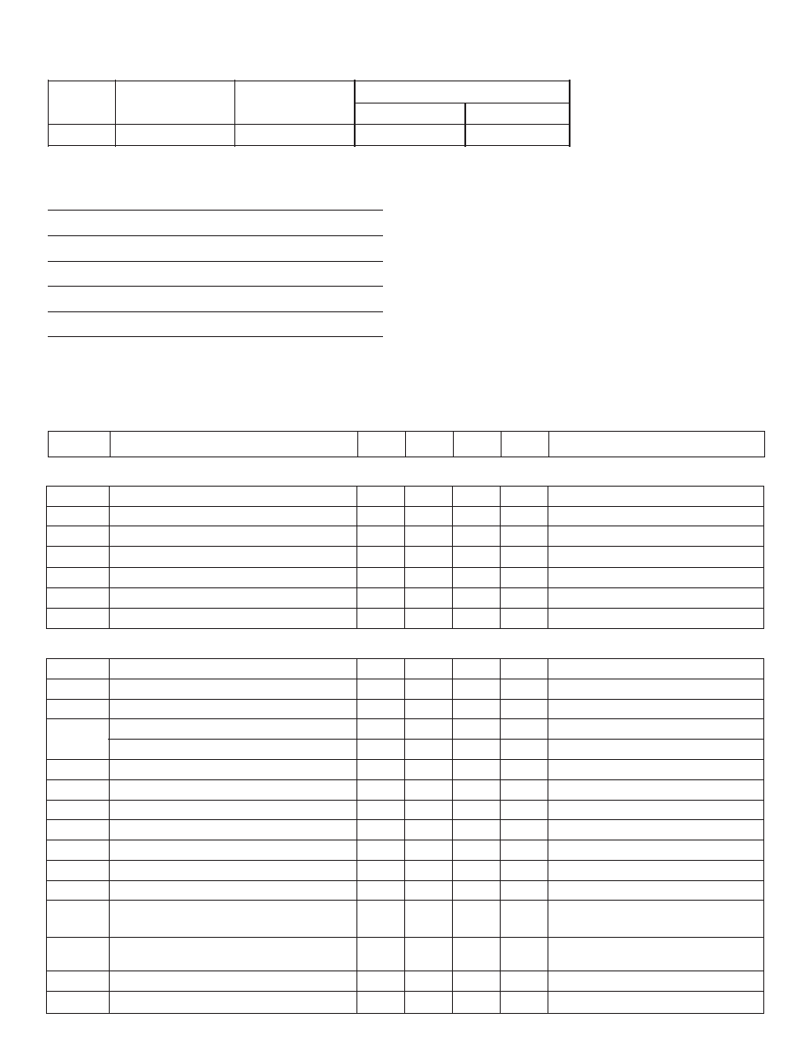
Electrical Characteristics
(Over operating conditions unless otherwise noted.)
Ordering Information
e
c
i
v
e
D
t
u
p
t
u
O
m
u
m
i
x
a
M
e
g
a
t
l
o
V
d
e
s
o
l
C
l
a
n
i
m
o
N
n
i
a
G
p
o
o
L
s
n
o
i
t
p
O
e
g
a
k
c
a
P
P
F
Q
M
d
a
e
L
100
ie
D
HV256
295V
72V/V
HV256FG
HV256X
Absolute Maximum Ratings*
V
PP
, High voltage supply
310V
V
DD
, Low voltage positive supply
8.0V
V
NN
, Low voltage negative supply
-7.0V
V
IN
, Analog input signal
0V to V
DD
Storage temperature range
-65∞C to 150∞C
Maximum junction temperature
150∞C
*Absolute Maximum Ratings are those values beyond which damage to the
device may occur. Functional operation under these conditions is not implied.
Continuous operation of the device at the absolute rating level may affect device
reliability. All voltages are referenced to device ground.
Parameter
Min
Typ
Max
Units
Condition
Symbol
Operating Conditions
High Voltage Amplifier

3
HV256
A112304
Parameter
Min
Typ
Max
Units
Condition
Symbol
Diode
V
I
P
ge
a
t
l
o
v
e
s
r
e
v
n
i
k
a
e
P
.0
5
e
d
o
n
a
o
t
e
d
o
h
t
a
c
V
F
p
o
r
d
e
d
o
i
d
d
r
a
w
r
o
F
0.60
0
0
1
=
f
I
µ
e
d
o
h
t
a
c
o
t
e
d
o
n
a
,
A
I
F
t
n
e
r
r
u
c
e
d
o
i
d
d
r
a
w
r
o
F
00
1
µA
e
d
o
h
t
a
c
o
t
e
d
o
n
a
T
C
V
F
t
n
e
i
c
i
f
f
e
o
c
e
r
u
t
a
r
e
p
m
e
t
-2.20
/
∞C
V
m
e
d
o
h
t
a
c
o
t
e
d
o
n
a
V
V
V
P
P
.
s
d
a
p
o
w
t
e
r
a
e
r
e
h
T
.
y
l
p
p
u
s
e
v
i
t
i
s
o
p
e
g
a
t
l
o
v
h
g
i
H
B
P
Y
V
-
P
P
V
s
s
o
r
c
a
r
o
t
i
c
a
p
a
c
g
n
il
p
u
o
c
e
d
F
n
0
1
o
t
0
.
1
e
g
a
t
l
o
v
w
o
l
A
P
P
B
d
n
a
P
Y
V
-
P
P
s
i
.
d
e
r
i
u
q
e
r
V
D
D
.
s
d
a
p
r
u
o
f
e
r
a
e
r
e
h
T
.
y
l
p
p
u
s
e
v
i
t
i
s
o
p
e
g
a
t
l
o
v
w
o
l
g
o
l
a
n
A
B
P
Y
V
-
D
D
V
s
s
o
r
c
a
r
o
t
i
c
a
p
a
c
g
n
il
p
u
o
c
e
d
F
n
0
1
o
t
0
.
1
e
g
a
t
l
o
v
w
o
l
A
D
D
B
d
n
a
P
Y
V
-
D
D
s
i
.
d
e
r
i
u
q
e
r
V
N
N
.
s
d
a
p
r
u
o
f
e
r
a
e
r
e
h
T
.
y
l
p
u
s
e
v
i
t
a
g
e
n
e
g
a
t
l
o
v
w
o
l
g
o
l
a
n
A
B
P
Y
V
-
N
N
V
s
s
o
r
c
a
r
o
t
i
c
a
p
a
c
g
n
il
p
u
o
c
e
d
F
n
0
1
o
t
0
.
1
e
g
a
t
l
o
v
w
o
l
A
N
N
B
d
n
a
P
Y
V
-
N
N
s
i
.
d
e
r
i
u
q
e
r
D
GN
s.
d
a
p
r
u
o
f
e
r
a
e
r
e
h
T
.
d
n
u
o
r
g
e
c
i
v
e
D
R
E
C
R
U
O
S
R
m
o
r
f
r
o
t
s
i
s
e
r
l
a
n
r
e
t
x
E
E
C
R
U
O
S
V
o
t
N
N
.
t
i
m
il
g
n
i
c
r
u
o
s
t
n
e
r
r
u
c
t
u
p
t
u
o
s
t
e
s
.
e
u
l
a
v
r
o
t
s
i
s
e
r
e
c
r
u
o
s
R
y
b
d
e
d
i
v
i
d
V
5
.
2
1
y
l
e
t
a
m
i
x
o
r
p
p
a
s
i
t
i
m
il
t
n
e
r
r
u
C
R
K
N
I
S
R
m
o
r
f
r
o
t
s
i
s
e
r
l
a
n
r
e
t
x
E
K
N
I
S
V
o
t
N
N
t
n
e
r
r
u
C
.
t
i
m
il
g
n
i
k
n
i
s
t
n
e
r
r
u
c
t
u
p
t
u
o
s
t
e
s
R
y
b
d
e
d
i
v
i
d
V
5
.
2
1
y
l
e
t
a
m
i
x
o
r
p
p
a
s
i
t
i
m
il
K
N
I
S
.
e
u
l
a
v
r
o
t
s
i
s
e
r
e
d
o
n
A
e
i
d
r
o
t
i
n
o
m
o
t
d
e
s
u
e
b
n
a
c
t
a
h
t
e
d
o
i
d
n
o
c
il
i
s
e
g
a
t
l
o
v
w
o
l
a
f
o
e
d
i
s
e
d
o
n
A
.
e
r
u
t
a
r
e
p
m
e
t
e
d
o
h
t
a
C
e
i
d
r
o
t
i
n
o
m
o
t
d
e
s
u
e
b
n
a
c
t
a
h
t
e
d
o
i
d
n
o
c
il
i
s
e
g
a
t
l
o
v
w
o
l
a
f
o
e
d
i
s
e
d
o
h
t
a
C
.
e
r
u
t
a
r
e
p
m
e
t
V
N
I
V
o
t
0
N
I
1
3
.
s
t
u
p
n
i
r
e
i
f
il
p
m
A
V
H
T
U
O
V
H
o
t
0
T
U
O
1
3
. s
t
u
p
t
u
o
r
e
i
f
il
p
m
A
Acceptable Power Up Sequences
1) V
PP
2) V
NN
3) V
DD
4) Inputs & Anode
or
1) V
NN
2) V
DD
3) V
PP
4) Inputs & Anode
Acceptable Power Down Sequences
1) Inputs & Anode
2) V
DD
3) V
NN
4) V
PP
or
1) Inputs & Anode
2) V
PP
3) V
DD
4) V
NN
Power Up/Down Sequence
The device can be damaged due to improper power up / down
sequence. To prevent damage, please follow the acceptable
power up /down sequences and add two external diodes as shown
in the diagram below. The first diode is a high voltage diode
across V
PP
and V
DD
where the anode of the diode is connected
to V
DD
and the cathode of the diode is connected to Vpp. Any low
current high voltage diode such as a 1N4004 will be adequate.
The second diode is a schottky diode across V
NN
and DGnd where
the anode of the schottky diode is connected to V
NN
and the
cathode is connected to DGnd. Any low current schottky diode
such as a 1N5817 will be adequate.
V
DD
V
PP
1N4004
or similar
V
NN
PGND
1N5817
or similar
Pin Description
4
HV256
A112304
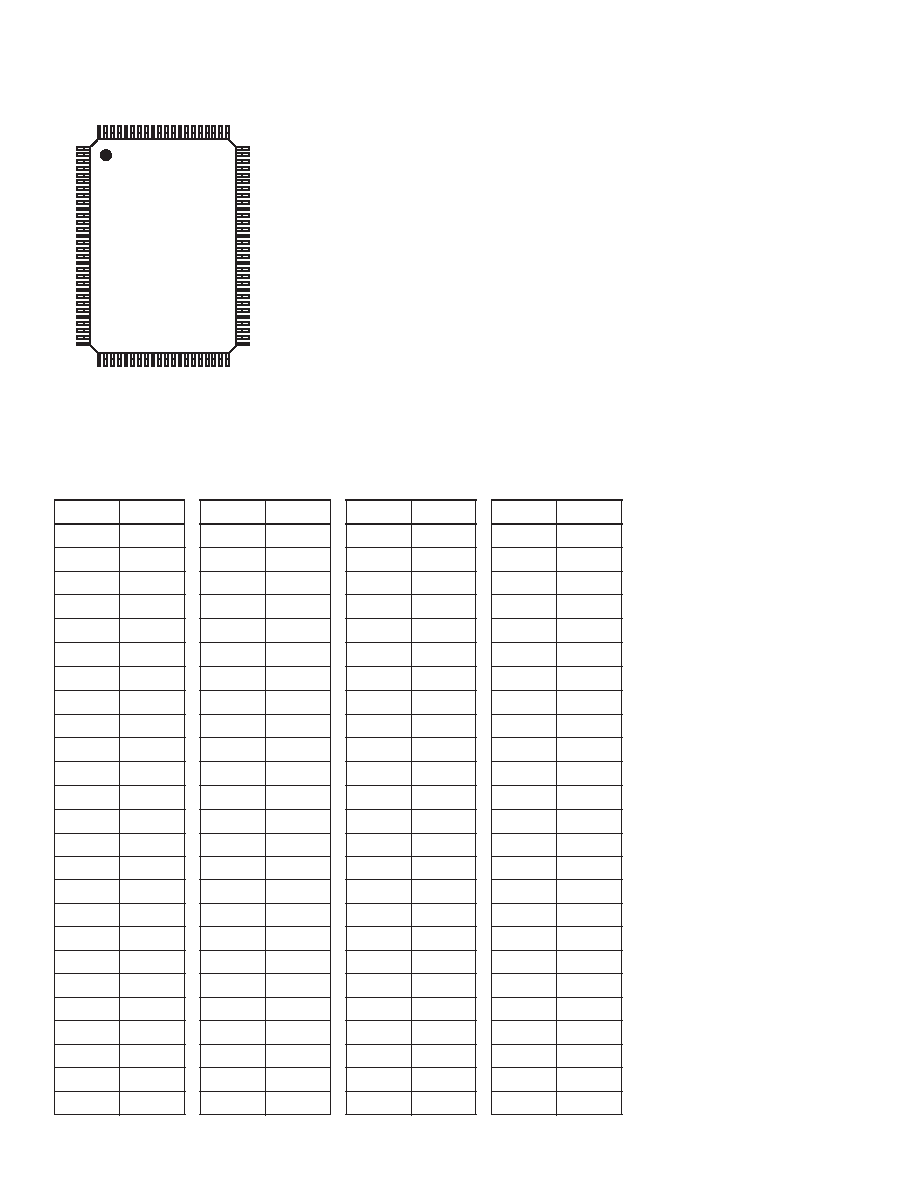
Pin Configuration
Pin Configuration
#
n
i
P
n
o
i
t
c
n
u
F
#
n
i
P
n
o
i
t
c
n
u
F
#
n
i
P
n
o
i
t
c
n
u
F
#
n
i
P
n
o
i
t
c
n
u
F
1
V
H
T
U
O
1
3
6
2
V
H
T
U
O
6
1
5
V
N
I
3
6
7
V
N
I
8
2
2
V
H
T
U
O
0
3
7
2
V
H
T
U
O
5
2
5
V
N
I
4
7
7
V
N
I
9
2
3
V
H
T
U
O
9
2
8
2
V
H
T
U
O
4
3
5
I
V
N
I
5
8
7
V
N
I
0
3
4
V
H
T
U
O
8
2
9
2
V
H
T
U
O
3
4
5
V
N
I
6
9
7
V
N
I
1
3
5
V
H
T
U
O
7
2
0
3
V
H
T
U
O
2
5
5
V
N
I
7
0
8
C
N
6
V
H
T
U
O
6
2
1
3
V
H
T
U
O
1
6
5
V
N
I
8
1
8
C
N
7
V
H
T
U
O
5
2
2
3
V
H
T
U
O
0
7
5
V
N
I
9
2
8
C
N
8
V
H
T
U
O
4
2
3
3
V
P
P
8
5
V
N
I
0
1
3
8
C
N
9
V
H
T
U
O
3
2
4
3
C
N
9
5
V
N
I
1
1
4
8
C
N
0
1
V
H
T
U
O
2
2
5
3
C
N
0
6
V
N
I
2
1
5
8
C
N
1
1
V
H
T
U
O
1
2
6
3
C
N
1
6
V
N
I
3
1
6
8
d
n
G
2
1
V
H
T
U
O
0
2
7
3
C
N
2
6
V
N
I
4
1
7
8
V
D
D
3
1
V
H
T
U
O
9
1
8
3
C
N
3
6
V
N
I
5
1
8
8
V
N
N
4
1
V
H
T
U
O
8
1
9
3
d
n
G
4
6
I
V
N
I
6
1
9
8
d
n
G
5
1
V
H
T
U
O
7
1
0
4
V
N
N
5
6
V
N
I
7
1
0
9
C
N
6
1
V
H
T
U
O
6
1
1
4
C
N
6
6
V
N
I
8
1
1
9
V
D
D
7
1
V
H
T
U
O
5
1
2
4
V
D
D
7
6
V
N
I
9
1
2
9
V
-
p
y
B
N
N
8
1
V
H
T
U
O
4
1
3
4
d
n
G
8
6
V
N
I
0
2
3
9
V
-
p
y
B
D
D
9
1
V
H
T
U
O
3
1
4
4
V
N
N
9
6
V
N
I
1
2
4
9
V
N
N
0
2
V
H
T
U
O
2
1
5
4
V
D
D
0
7
V
N
I
2
2
5
9
e
d
o
n
A
1
2
V
H
T
U
O
1
1
6
4
C
N
1
7
V
N
I
3
2
6
9
e
d
o
h
t
a
C
2
2
V
H
T
U
O
0
1
7
4
C
N
2
7
V
N
I
4
2
7
9
R
K
N
I
S
3
2
V
H
T
U
O
9
8
4
V
N
I
0
3
7
V
N
I
5
2
8
9
R
E
C
R
U
O
S
4
2
V
H
T
U
O
8
9
4
V
N
I
1
4
7
V
N
I
6
2
9
9
V
-
p
y
B
P
P
5
2
V
H
T
U
O
7
0
5
V
N
I
2
5
7
V
N
I
7
2
0
0
1
V
P
P
.
t
c
e
n
n
o
C
o
N
=
C
N
100-Lead MQFP
(top view)
1
100
30
31
50
80
51
81

5
HV256
A112304
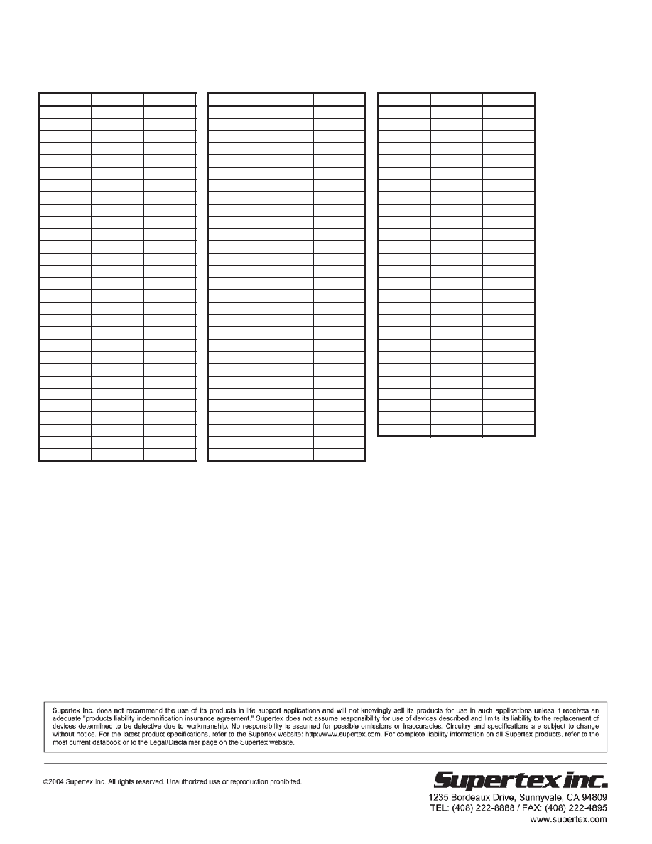
Pad Configuration
(Not Drawn to Scale)
6
HV256
A112304
Pad Coordinates
Chip Size: 17004µm x 5480µm
Center of die is (0,0)
e
m
a
N
d
a
P
)
m
µ
(
X
)
m
µ
X(
m)
µ
X(
m)
µ
Y(
me
a
N
d
Pa
m)
µ
X(
m)
µ
(
Y
V
P
P
5
.
8
3
3
8
-
5
.
8
0
7
2
V
H
T
U
O
8
2
5
.
0
2
6
4
5
.
5
0
3
2
V
N
I
0
2
5
.
8
8
5
0
.
6
8
6
2
-
V
H
T
U
O
0
0
.
5
9
8
7
-
5
.
5
0
3
2
V
H
T
U
O
9
2
5
.
7
6
0
5
5
.
5
0
3
2
V
N
I
9
1
5
.
3
8
1
0
.
6
8
6
2
-
V
H
T
U
O
1
5
.
8
4
4
7
-
5
.
5
0
3
2
V
H
T
U
O
0
3
5
.
4
1
5
5
5
.
5
0
3
2
V
N
I
8
1
5
.
1
2
2
-
0
.
6
8
6
2
-
V
H
T
U
O
2
5
.
1
0
0
7
-
5
.
5
0
3
2
V
H
T
U
O
1
3
5
.
1
6
9
5
5
.
5
0
3
2
V
N
I
7
1
5
.
6
2
6
-
0
.
6
8
6
2
-
V
H
T
U
O
3
5
.
4
5
5
6
-
5
.
5
0
3
2
V
P
P
9
5
6
6
9
0
7
2
V
N
I
6
1
5
.
1
3
0
1
-
0
.
6
8
6
2
-
V
H
T
U
O
4
5
.
7
0
1
6
-
5
.
5
0
3
2
V
-
p
y
B
P
P
5
4
0
7
9
0
7
2
V
N
I
5
1
5
.
6
3
4
1
-
0
.
6
8
6
2
-
V
H
T
U
O
5
5
.
0
6
6
5
-
5
.
5
0
3
2
R
E
C
R
U
O
S
9
8
4
7
9
0
7
2
V
N
I
4
1
0
.
2
1
4
2
-
0
.
6
8
6
2
-
V
H
T
U
O
6
5
.
3
1
2
5
-
5
.
5
0
3
2
R
K
N
I
S
9
6
9
7
9
0
7
2
V
N
I
3
1
7
1
8
2
-
0
.
6
8
6
2
-
V
H
T
U
O
7
5
.
6
6
7
4
-
5
.
5
0
23
8366
09
27
N
I
2
1
2
2
2
3
-
0
.
6
8
6
2
-
V
H
T
U
O
8
5
.
9
1
3
4
-
5
.
5
0
23
Anode
8366
99
21
N
I
1
1
7
2
6
3
-
0
.
6
8
6
2
-
V
H
T
U
O
9
5
.
2
7
8
3
-
5
.
5
0
3
2
V
N
N
7
4
0
8
0
.
5
2
4
V
N
I
0
1
2
3
0
4
-
0
.
6
8
6
2
-
V
H
T
U
O
0
1
5
.
5
2
4
3
-
5
.
5
0
3
2
V
-
p
y
B
D
D
7
4
0
8
5
.
5
2
1
V
N
I
9
7
3
4
4
-
0
.
6
8
6
2
-
V
H
T
U
O
1
1
5
.
8
7
9
2
-
5
.
5
0
3
2
V
-
p
y
B
N
N
7
4
0
8
5
.
5
4
3
-
V
N
I
8
2
4
8
4
-
0
.
6
8
6
2
-
V
H
T
U
O
2
1
5
.
1
3
5
2
-
5
.
5
0
3
2
V
D
D
7
4
0
8
5
.
4
0
7
-
V
N
I
7
7
4
2
5
-
0
.
6
8
6
2
-
V
H
T
U
O
3
1
5
.
4
8
0
2
-
5
.
5
0
23
GND
47
80
.0
4
2
4
-1
N
I
6
2
5
6
5
-
0
.
6
8
6
2
-
V
H
T
U
O
4
1
5
.
7
3
6
1
-
5
.
5
0
3
2
V
N
N
5
.
6
6
0
8
0
.
0
9
5
1
-
V
N
I
5
2
5
0
6
-
0
.
6
8
6
2
-
V
H
T
U
O
5
1
5
.
0
9
1
1
-
5
.
5
0
3
2
V
D
D
5
.
6
6
0
8
5
.
8
5
9
1
-
V
N
I
4
2
6
4
6
-
0
.
6
8
6
2
-
V
H
T
U
O
6
1
5
.
3
4
7
-
5
.
5
0
23
GND
.0
7
6
78
.0
2
9
1
-2
N
I
3
7
6
8
6
-
0
.
6
8
6
2
-
V
H
T
U
O
7
1
5
.
6
9
2
-
5
.
5
0
3
2
V
N
I
1
3
5
.
3
4
0
5
0
.
6
8
6
2
-
V
N
I
2
2
7
2
7
-
0
.
6
8
6
2
-
V
H
T
U
O
8
1
0
.
0
5
1
5
.
5
0
3
2
V
N
I
0
3
5
.
8
3
6
4
0
.
6
8
6
2
-
V
N
I
1
7
7
6
7
-
0
.
6
8
6
2
-
V
H
T
U
O
9
1
5
.
7
9
5
5
.
5
0
3
2
V
N
I
9
2
5
.
3
3
2
4
0
.
6
8
6
2
-
V
N
I
0
2
8
0
8
-
0
.
6
8
6
2
-
V
H
T
U
O
0
2
5
.
4
4
0
1
5
.
5
0
3
2
V
N
I
8
2
5
.
8
2
8
3
0
.
6
8
6
2
-
V
D
D
3
7
3
8
-
5
.
0
5
2
2
-
V
H
T
U
O
1
2
5
.
1
9
4
1
5
.
5
0
3
2
V
N
I
7
2
5
.
3
2
4
3
0
.
6
8
6
2
-
V
N
N
3
7
3
8
-
0
.
9
4
9
1
-
V
H
T
U
O
2
2
5
.
8
3
9
1
5
.
5
0
3
2
V
N
I
6
2
5
.
8
1
0
3
0
.
6
8
6
-2
67
3
-8
.
1
6
5
1
-
V
H
T
U
O
3
2
5
.
5
8
3
2
5
.
5
0
3
2
V
N
I
5
2
5
.
3
1
6
2
0
.
6
8
6
2
-
V
D
D
7
8
3
-8
.0
3
4
1
1
-
V
H
T
U
O
4
2
5
.
2
3
8
2
5
.
5
0
3
2
V
N
I
4
2
5
.
8
0
2
2
0
.
6
8
6
2
-
V
N
N
5
.
8
3
3
8
-
5
.
7
7
5
V
H
T
U
O
5
2
5
.
9
7
2
3
5
.
5
0
3
2
V
N
I
3
2
5
.
3
0
8
1
0
.
6
8
6
-2
.0
1
4
3
-8
.5
6
1
9
V
H
T
U
O
6
2
5
.
6
2
7
3
5
.
5
0
3
2
V
N
I
2
2
5
.
8
9
3
1
0
.
6
8
6
2
-
V
H
T
U
O
7
2
5
.
3
7
1
4
5
.
5
0
3
2
V
N
I
1
2
5
.
3
9
9
0
.
6
8
6
2
-
Pad Name
Cathode
V
V
GND
GND
V
V
DOC #: DSFP-HV256 A112304
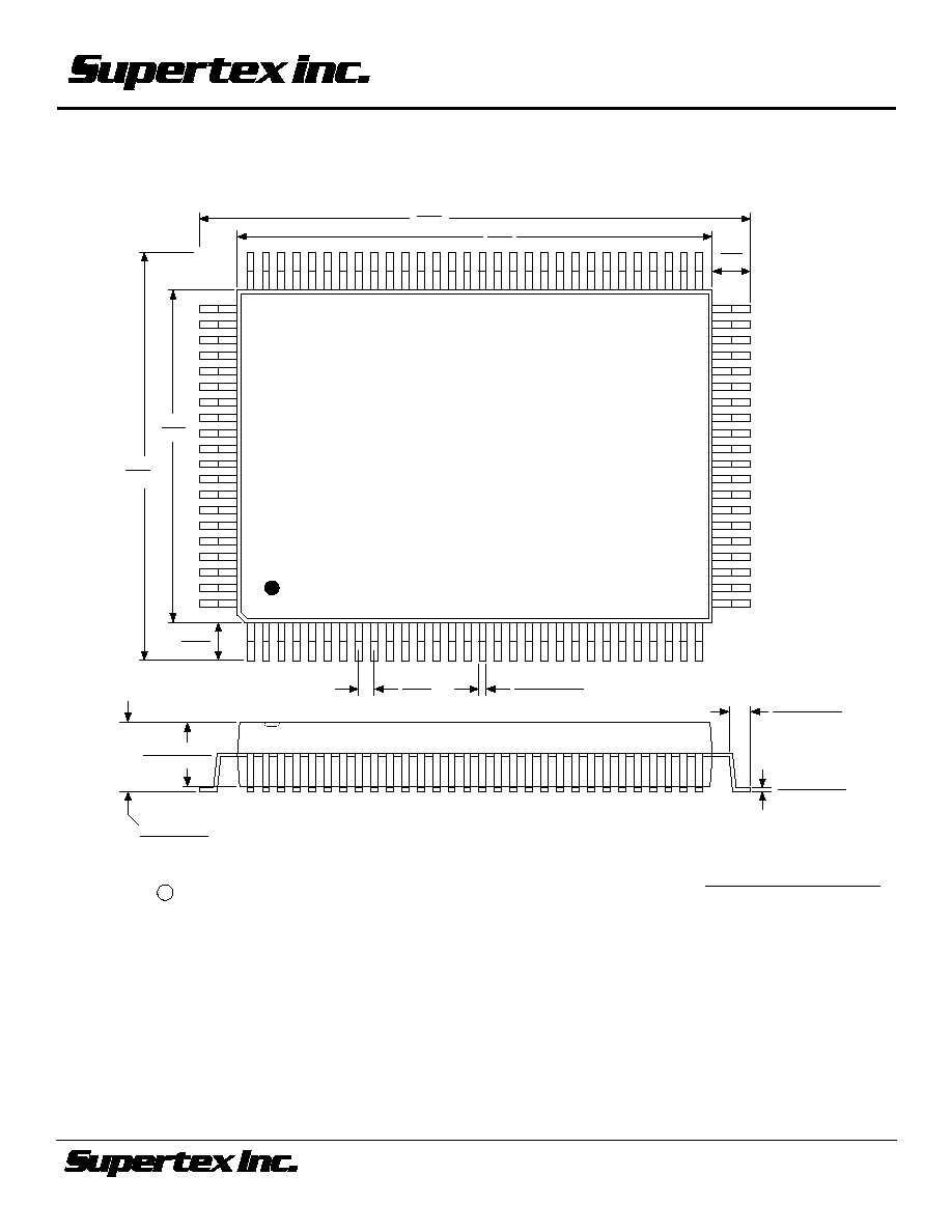
Package Outlines
1235 Bordeaux Drive, Sunnyvale, CA 94089
TEL: (408) 222-8888 / FAX: (408) 222-4895
www.supertex.com
A052104
©2004 Supertex Inc. All rights reserved. Unauthorized use or reproduction prohibited.
Note: Circle (e.g. B ) indicates JEDEC Reference.
Dimensions in Inches
(Dimensions in Millimeters)
Measurement Legend =
0.787
(20.0)
0.913
(23.2)
0.551
(14.0)
0.677
(17.2)
0.063
(1.6)
0.063
(1.6)
1
30
31
50
51
70
71
100
0.0346
± 0.0059
(0.88
± 0.15)
0.0067
± 0.0024
(0.17
± 0.06)
0.0118
± 0.0031
(0.30
± 0.08)
0.0256
(0.65)
0.1063
± 0.0079
(2.70
± 0.20)
0.0111
± 0.013
(2.825
± 0.325)
100-LEAD MQFP PACKAGE OUTLINE (FG)
Doc. #: DSPD-100MQFPFG