DISTRIBUTION MODULES
DISTRIBUTION MODULES
Low Phase Noise
High Channel Isolation
Ten Channel Output Distribution
Daisy Chain For More Than 100 Outputs
Features
Over
view
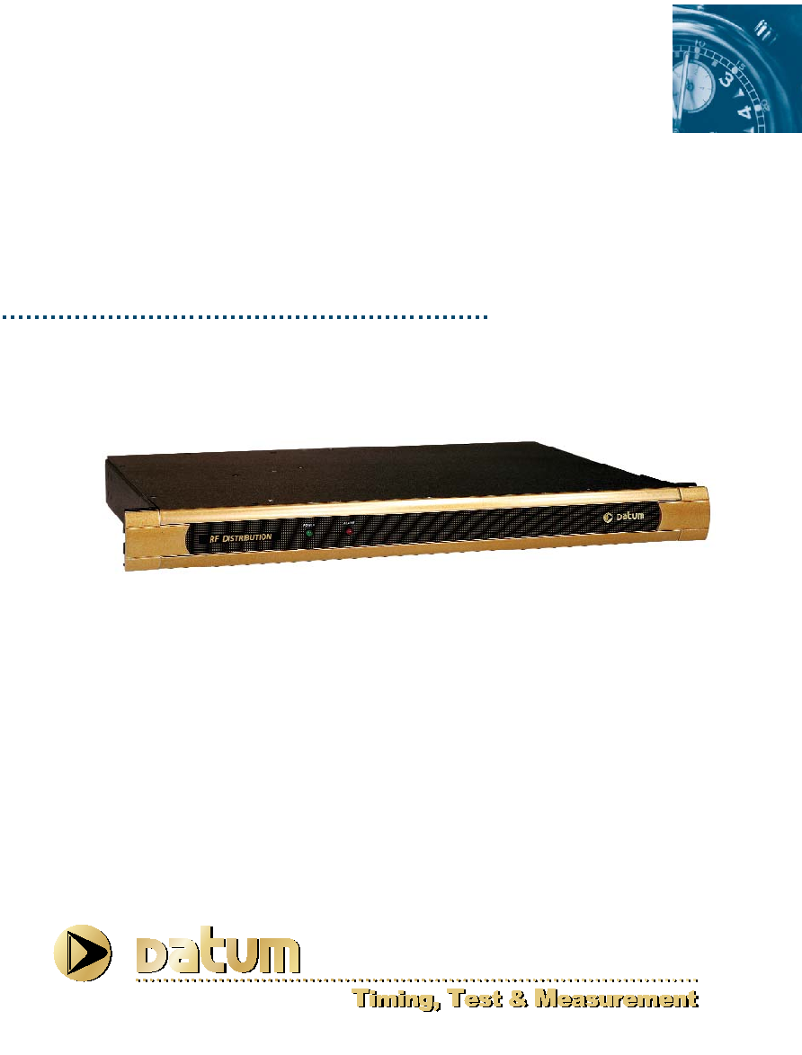
The DATUM 6502 Distribution Module is a
ten channel, RF distribution amplifier pack-
aged in a 1U rack mount chassis. It is com-
prised of ten low phase noise RF amplifiers
that maintain high channel isolation
(>100dB). Up to ten units can be daisy
chained together to give up to 100 outputs
or each output of one unit can be used as a
source for other 6502 units to give almost
infinite expansion capability with virtually no
signal degradation.
The 6502 standard configuration accepts
input frequencies from 0.1MHz to 10MHZ at
1Vrms amplitude and provides ten buffered
outputs of the same frequency. Each output
and input has an alarm indicator that warns
of either a loss of signal or a signal of insuf-
ficient amplitude.
The 6502 is also available in custom config-
urations. Please contact Datum - TT&M
with any specific requirements.
6502 RF Distribution Module

Datum
-TT&M
∑
34 Tozer Road
∑
Beverly, MA 01915-5510
∑
Tel: +1-978-927-8220
∑
Fax; +1-978-927-4099
USA Toll Free:
1-800-544-0233
∑
Web:
www.datum.com
∑
E-mail:
ttmsales@datum.com
Specifications subject to change without notice.
Rev 4-02
DISTRIBUTION MODULES
DISTRIBUTION MODULES
Specifications subject to change without notice.
Specifications
ELECTRICAL SPECIFICATIONS
RF Output (ten)
Frequency
0.1 to 10 MHz
Level
1 V rms (nominal)
Harmonic Distortion
< -40 dB
Non-Harmonic signals
< -80 dB
Load Impedance
50
Isolation >100
dB*
Connectors BNC
*Isolation between channels one to ten >130 dB
Additive SSB Phase Noise
(1 Hz Bandwidth)Offset from carrier
1 Hz
-120 dB
10 Hz
-135 dB
100 Hz
-145 dB
1,000 Hz
-155 dB
10,000 Hz
-160 dB
RF Input
Frequency
0.1 to 10 MHz
Level
1 V rms (nominal)
Alarm Output
Summary alarm indicates failure of any output signal.
Each Output & Main
Red LED
Non-alarm condition
Relay energized (fail safe)
C Form contacts
Alarm O/P Disable
Panel switch
Connector
9 pin D-male
Controls & Indicators
Power
Green LED, power is connected
Alarm
Red LED, signal output failure
Alarm Override
Toggle Switch:
(optional for 6502B)
Up = Alarm Enabled
Down = Alarm Disabled
Please note:
If input level is less than 10dBm specify
low alarm threshold version (-509).
ENVIRONMENTAL & PHYSICAL SPECIFICATIONS
Temperature
(operating)
0∫ to 55∞C
Relative Humidity
0 to 95%,
non-condensing
Power Requirements
AC Input (+/-15%)
120 or 230 V AC, <10W
DC Input (optional)
20 to 70 V DC, 10W
Dimensions
Height
1U (~1.75 inches)
Width 19
inches
Depth 12
inches
Weight
<5 lbs.
6502 RF Distribution Module
∑ Front mounted connectors
502
Options
Option P/N