BZX7
9C
3V
3 thr
o
ugh BZX
79C
5
6
Se
rie
s
500 mW DO-35 Hermetically
Sealed Glass Zener Voltage
Regulators
Absolute Maximum Ratings
T
A
= 25∞C unless otherwise noted
Parameter Value
Units
Power Dissipation
500
mW
Storage Temperature Range
-65 to +200
∞C
Operating Junction Temperature
+200
∞C
Lead Temperature (1/16" from case for 10 seconds)
+230
∞C
These ratings are limiting values above which the serviceability of the diode may be impaired.
Specification Features:
Zener Voltage Range 3.3 to 56 Volts
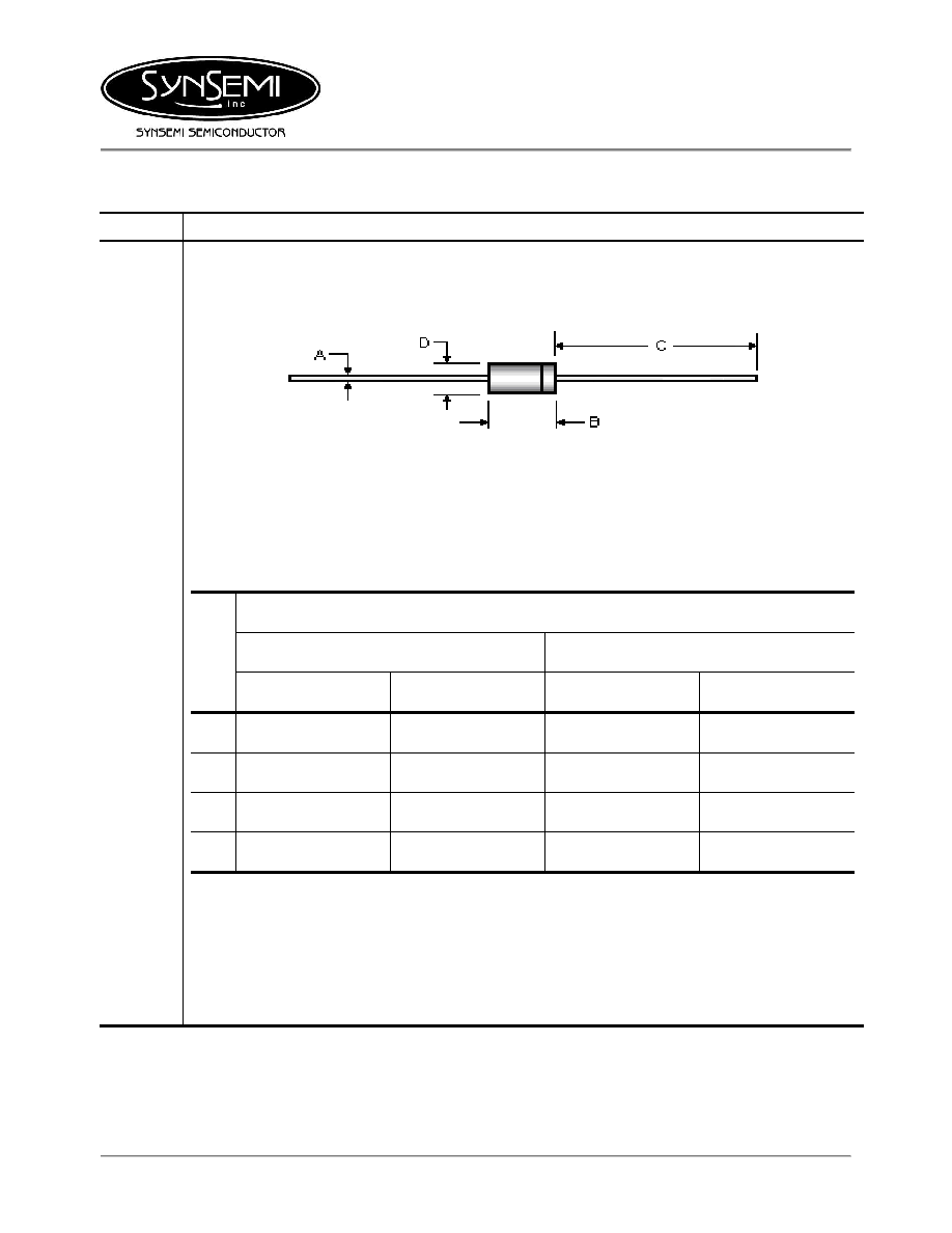
DO-35 Package (JEDEC)
Through-Hole Device Type Mounting
Hermetically Sealed Glass
Compression Bonded Construction
All external surfaces are corrosion resistant and leads are readily solderable
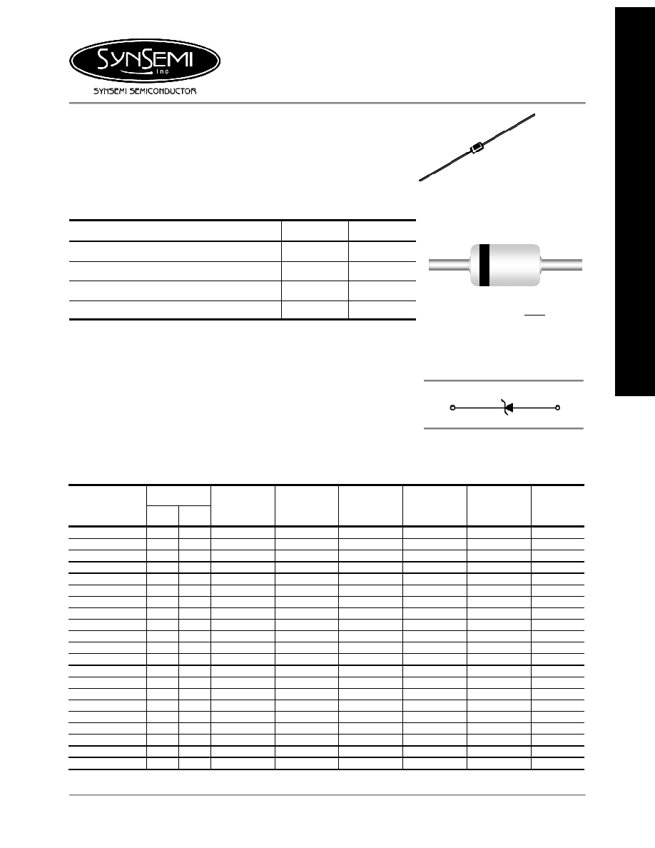
Cathode indicated by polarity band
AXIAL LEAD
DO-35
DEVICE MARKING DIAGRAM
L
79C
xxx
L :
Logo
Device Code : BZX79Cxxx
Cathode
Anode
ELECTRICAL SYMBOL
Electrical Characteristics
T
A
= 25∞C unless otherwise noted
V
Z
@ I
ZT
(Volts)
Device Type
V
Z
Min
V
Z
Max
I
ZT
(mA)
Z
ZT
@ I
ZT
(
)
Max
I
ZK
(mA)
Z
ZK
@ I
ZK
(
)
Max
I
R
@ V
R
(
µ
A)
Max
V
R
(Volts)
BZX79C
3V3
3.1
3.5
5 95 1 600 25
1
BZX79C
3V6
3.4
3.8
5 90 1 600 15
1
BZX79C
3V9
3.7
4.1
5 90 1 600 10
1
BZX79C
4V3
4
4.6
5 90 1 600 5 1
BZX79C
4V7
4.4
5
5 80 1 500 3 2
BZX79C
5V1
4.8
5.4
5 60 1 480 2 2
BZX79C
5V6
5.2
6
5 40 1 400 1 2
BZX79C
6V2
5.8
6.6
5 10 1 150 3 4
BZX79C
6V8
6.4
7.2
5 15 1 80 2 4
BZX79C
7V5
7
7.9
5 15 1 80 1 5
BZX79C
8V2
7.7
8.7
5 15 1 80 0.7
5
BZX79C
9V1
8.5
9.6
5 15 1 100
0.5
6
BZX79C
10
9.4
10.6
5 20 1 150
0.2
7
BZX79C
11
10.4
11.6
5 20 1 150
0.1
8
BZX79C
12
11.4
12.7
5 25 1 150
0.1
8
BZX79C
13
12.4
14.1
5 30 1 170
0.1
8
BZX79C
15
13.8
15.6
5 30 1 200
0.05
10.5
BZX79C
16
15.3
17.1
5 40 1 200
0.05
11.2
BZX79C
18
16.8
19.1
5 45 1 225
0.05
12.6
BZX79C
20
18.8
21.2
5 55 1 225
0.05
14
BZX79C
22
20.8
23.3
5 55 1 250
0.05
15.4
October 2003 / B
Electrical Characteristics
T
A
= 25∞C unless otherwise noted
V
Z
@ I
ZT
(Volts)
Device Type
V
Z
Min
V
Z
Max
I
ZT
(mA)
Z
ZT
@ I
ZT
(
)
Max
I
ZK
(mA)
Z
ZK
@ I
ZK
(
)
Max
I
R
@ V
R
(
µ
A)
Max
V
R
(Volts)
BZX79C
24
22.8
25.6
5 70 1 250
0.05
16.8
BZX79C 27
25.1
28.9
5
80
0.5
300
0.05
18.9
BZX79C 30
28
32
5
80
0.5
300
0.05
21
BZX79C 33
31
35
5
80
0.5
325
0.05
23.1
BZX79C 36
34
38
5
90
0.5
350
0.05
25.2
BZX79C 39
37
41
5
130
0.5
350
0.05
27.3
BZX79C 43
40
46
2
150
0.5
375
0.05
30.1
BZX79C 47
44
50
2
170
0.5
375
0.05
32.9
BZX79C 51
48
54
2
180
0.5
400
0.05
35.7
BZX79C 56
52
60
2
200
0.5
425
0.05
39.2
V
F
Forward Voltage = 1.5 V Maximum @ I
F
= 100 mA for all types
Notes:
1. The type numbers listed have zener voltage min/max limits as shown.
2. For detailed information on price, availability and delivery of nominal zener voltages between the voltages shown and tighter
voltage tolerances, contact your nearest Synsemi representative.
3. The zener impedance is derived from the 60-cycle ac voltage, which results when an ac current having an rms value equal to
10% of the dc zener current (I
ZT
or I
ZK
) is superimposed to I
ZT
or I
ZK.
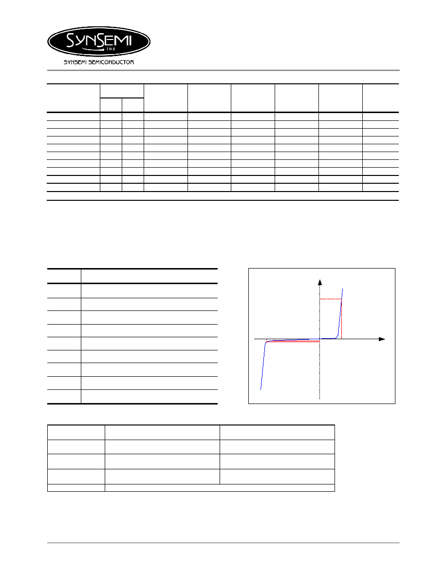
Electrical Symbol Definition
Typical Characteristics
Symbol Parameter
V
Z
Reverse Zener Voltage @ I
ZT
I
ZT
Reverse Current
Z
ZT
Maximum Zener Impedance @ I
ZT
I
ZK
Reverse Current
Z
ZK
Maximum Zener Impedance @ I
ZK
I
R
Reverse Leakage Current @ V
R
V
R
Breakdown Voltage
I
F
Forward Current
V
F
Forward Voltage @ I
F
(nA)
V
Z
V
R
I
R
I
ZT
I
F
V
F
(mA)
(mA)
(V)
(mV)
I
V
Ordering Information
Device Package
Quantity
BZX79Cxxx Bulk
10,000
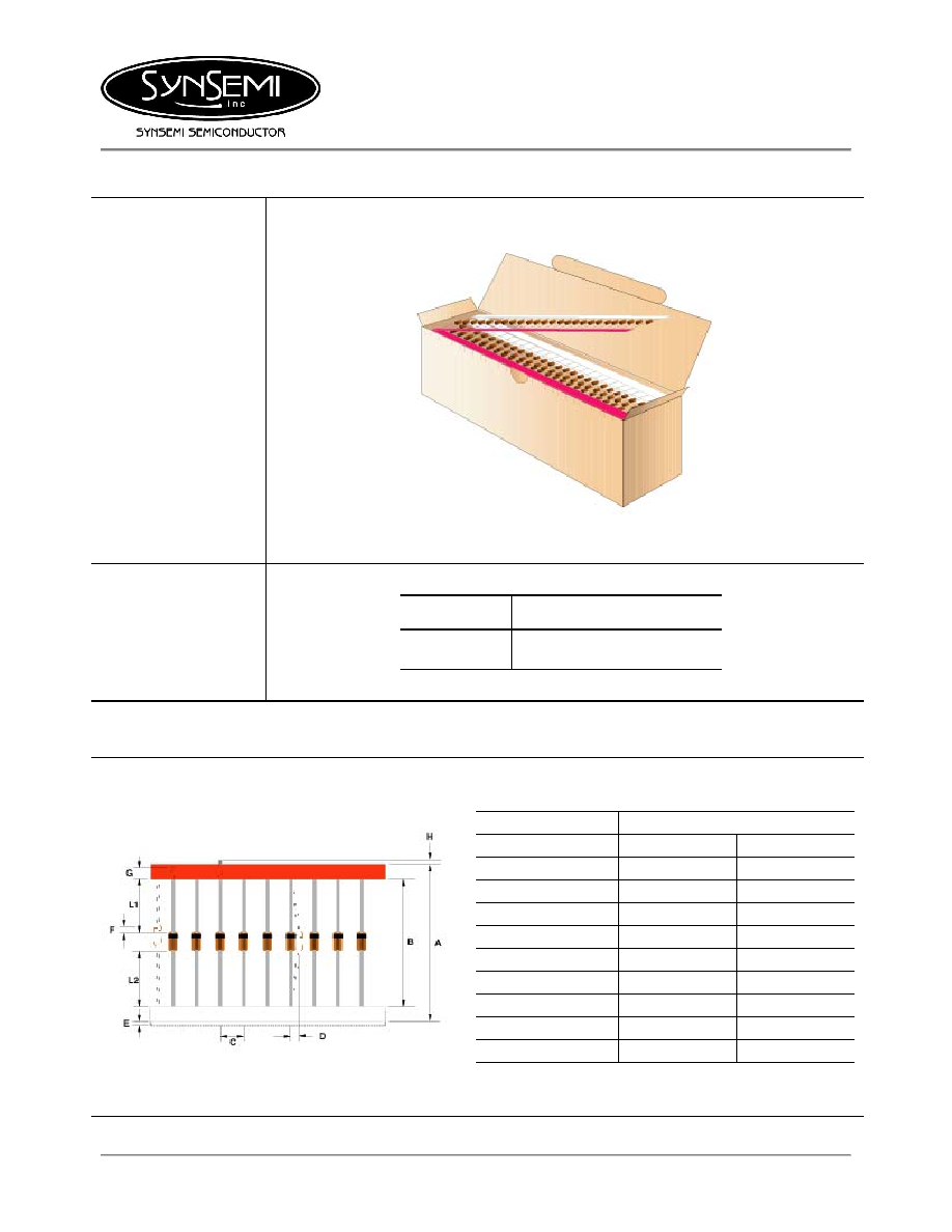
BZX79Cxxx.TB Tape
and
Ammo
5,000
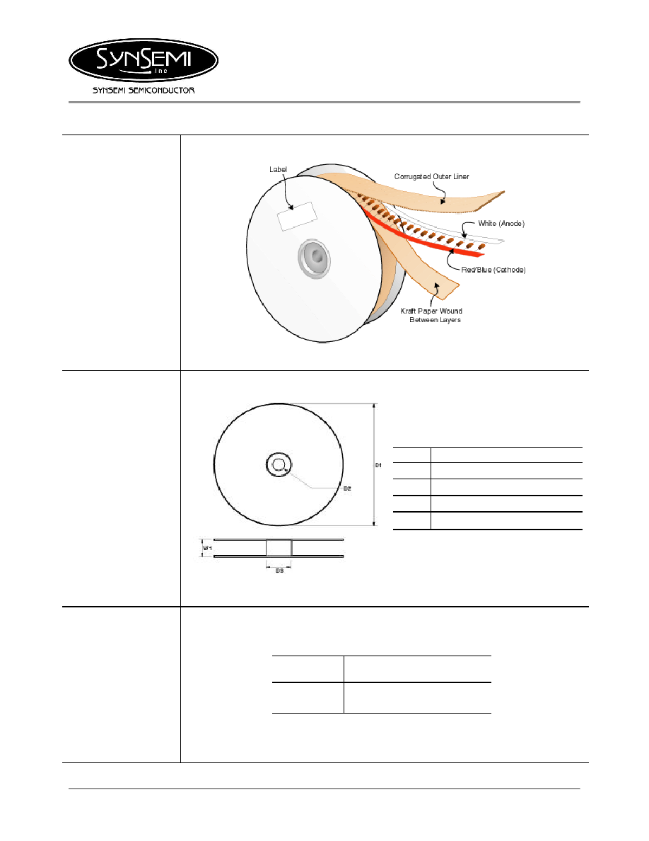
BZX79Cxxx.TR Tape
and
Reel
10,000
October 2003 / B