
73K222AU
Single-Chip Modem
Modem with UART
April 2000
DESCRIPTION
The 73K222AU is a compact, high-performance
modem which includes a 8250A/16C450 compatible
UART with the 1200 bit/s modem function on a
single chip. Based on the 73K222L 5V low power
CMOS modem IC, the 73K222AU is the perfect
modem/UART component for integral modem
applications. It is ideal for applications such as
portable terminals and laptop computers. The
73K222AU is the first fully featured modem IC which
can function as an intelligent modem in integral
applications without requiring a separate dedicated
microcontroller. It provides for data communication
at 1200, 600, and 300 bit/s in a multi-mode manner
that allows operation compatible with both Bell
212A/103 and CCITT V.22/V.21 standards. The
digital interface section contains a high speed
version of the industry standard 8250A/16C450
UART, commonly used in personal computer
products. A unique feature of the 73K222AU is that
the UART section can be used without the modem
function, providing an additional asynchronous port
at no added cost. The 73K222AU is designed in
CMOS technology and operates from a single +5V
supply. Available packaging includes 40-pin DIP or
44-pin PLCC for surface mount applications.
FEATURES
∑ Modem/UART combination optimized for
integral bus applications
∑ Includes features of 73K222L single-chip modem
∑ Fully compatible 16C450/8250 UART with
8250B or 8250A selectable interrupt emulation
∑ High speed UART will interface directly with
high clock rate bus with no wait states
∑ Single-port mode allows full modem and
UART control from CPU bus, with no
dedicated microprocessor required
∑ Dual-port mode suits conventional designs
using local microprocessor for transparent
modem operation
∑ Complete modem functions for 1200 bit/s (Bell
212A, V.22) and 0-300 bit/s (Bell 103, V.21)
∑ Includes DTMF generator, carrier, call-
progress and precise answer-tone detectors
for intelligent dialing capability
∑ On chip 2-wire/4-wire hybrid driver and off-
hook relay buffer
∑ Speaker output with four-level software driven
volume control
∑ Low power CMOS (40 mW) with power down
mode (15 mW)
∑ Operates from single +5V supply
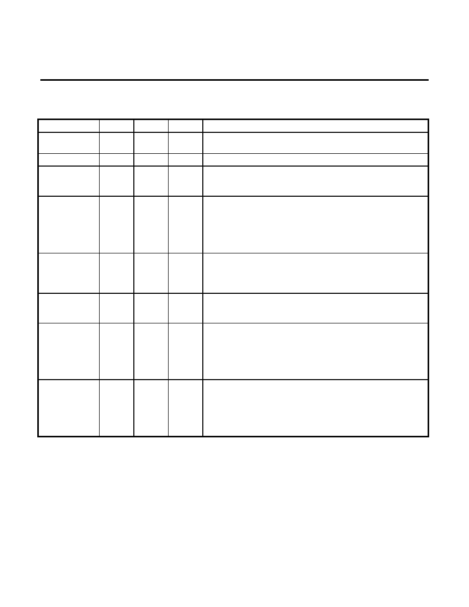
BLOCK DIAGRAM
UD0
UD1
UD2
UD3
UD4
UD5
UD6
UD7
UA0
UA1
UA2
INTRPT
(
) PRST
RESET
RXD
INT
OUT1
VDD VREF GND ISET STNDLN
(
) /
(
) / DCLK
/ (N/C)
/ (
)
DATA / (
)
(UA3) / MA2
(
) / MA1
(
) / MA0
SPKR
RXA
TXA2
TXA1
CLK
XTL2
XTL1
TXD
1.8432 MHz
INTERNAL DATA
8250A / 16C450
UART
73K222AL
2W/4W
HYBRID
2
RELAY
DRIVER
RXD-INPUT
OH

73K222AU
Single-Chip Modem
with UART
2
FUNCTIONAL DESCRIPTION
The 73K222AU integrates an industry standard
8250/16C450 UART function with the modem
capability provided by the 73K222L single chip
modem IC. The 73K222AU is designed specifically
for integral microprocessor bus intelligent modem
products. These designs typically require the
standard 8250 or higher speed 16450 UART to
perform parallel-to-serial and serial-to-parallel
conversion process necessary to interface a parallel
bus with the inherently serial modem function. The
73K222AU provides a highly integrated design
which can eliminate multiple components in any
integral bus modem application, and is ideal for
internal PC modem applications.
The 73K222AU includes two possible operating
modes. In the dual-port mode, the device is suitable
for conventional plug-in modem card designs which
use a separate local microprocessor for command
interpretation and control of the modem function. In
this mode, a dedicated microcontroller
communicates with the 73K222AU using a separate
serial command port. In the single-port mode the
main CPU can control both the UART and modem
function using the parallel data bus. This allows very
efficient modem design with no local microprocessor
required for dedicated applications such as laptop
PC's or specialized terminals.
To make designs more space efficient, the
73K222AU includes the 2-wire to 4-wire hybrid
drivers, off-hook relay driver, and an audio monitor
output with software volume control for audible call
progress monitoring. As an added feature the UART
function can be used independent of the modem
function, providing an added asynchronous port in a
typical PC application with no additional circuitry
required.
UART FUNCTION (16C450)
The UART section of the 73K222AU is completely
compatible with the industry standard 16C450 and
the 8250 UART devices. The bus interface is
identical to the 16450, except that only a single
polarity for the control signals is supported. The
register contents and addresses are also the same
as the 16C450. To insure compatibility with all
existing releases of the 8250 UART design, external
circuitry normally used in PC applications to emulate
8250B or 8250A interrupt operation has been
included on the 73K222AU. A select line is then
provided to enable the desired interrupt operation.
The UART used in the 73K222AU can be used with
faster bus read and write cycles than a conventional
16C450 UART. This allows it to interface directly
with higher clock rate microprocessors with no need
for external circuitry to generate wait states.
The primary function of the UART is to perform
parallel-to-serial conversion on data received from
the CPU and serial-to-parallel conversion on data
received from the internal modem or an external
device. The UART can program the number of bits
per character, parity bit generation and checking,
and the number of stop bits. The UART also
provides break generation and detection, detection
of error conditions, and reporting of status at any
time. A prioritized maskable interrupt is also
provided.
The UART block has a programmable baud rate
generator which divides an internal 1.8432 MHz
clock to generate a clock at 16 x the data rate. The
data rate for the transmit and receive sections must
be the same. For DPSK modulation, the data rate
must be 1200 Hz or 600 Hz. For FSK modulation,
the data rate must be 300 Hz or less. The baud
generator can create a clock that supports digital
transfer at up to 115.2 kHz. The output of the baud
generator can be made available at the CLK pin
under program control.
MODEM FUNCTION (73K222AL)
The modem section of the 73K222AU provides all
necessary analog functions required to create a
single chip Bell 212A/103 and CCITT V.22/V.21
modem, controlled by the system CPU or a local
dedicated microprocessor. Asynchronous 1200 bit/s
DPSK (Bell 212A and V.22) and 300 baud FSK (Bell
103 and V.21) modes are supported.
The modem portion acts as a peripheral to the
microprocessor. In both modes of operation, control
information is stored in register memory at specific
address locations. In the single-port mode, the
modem section can be controlled through the
16C450 interface, with no external microcontroller
required. The primary analog blocks are the DPSK
modulator/demodulator, the FSK modulator/
demodulator, the high and low band filters, the AGC,
the special detect circuitry, and the DTMF tone
generator. The analog functions are performed with
switched capacitor technology.

73K222AU
Single-Chip Modem
with UART
3
PSK MODULATOR / DEMODULATOR
The 73K222AU modulates a serial bit stream into
dibit pairs that are represented by four possible
phase shifts as prescribed by the Bell 212A or V.22
standard. The baseband signal is then filtered to
reduce intersymbol interference on the band limited
2-wire PSTN line. Transmission occurs using either
a 1200 Hz (originate mode) or 2400 Hz carrier
(answer mode). Demodulation is the reverse of the
modulation process, with the incoming analog signal
eventually decoded into dibits and converted back to
a serial bit stream. The demodulator also recovers
the clock which was encoded into the analog signal
during modulation. The demodulator decodes either
a 1200 Hz carrier (originate carrier) or a 2400 Hz
carrier (answer carrier). The 73K222AU uses a
phase-locked-loop coherent demodulation technique
that offers inherently better performance than typical
DPSK demodulators used by other manufacturers.
FSK MODULATOR/DEMODULATOR
The FSK modulator frequency modulates the analog
output signal using two discrete frequencies to
represent the binary data. In Bell 103, the standard
frequencies of 1270 Hz and 1070 Hz (originate mark
and space) and 2225Hz and 2025 Hz (answer mark
and space) are used. V.21 mode uses 980 Hz and
1180 Hz (originate, mark and space) or 1650 Hz and
1850 Hz (answer, mark and space). Demodulation
involves detecting the received frequencies and
decoding them into the appropriate binary value.
PASSBAND FILTERS AND EQUALIZERS
A high and low band filter is included to shape the
amplitude and phase response of the transmit signal
and provide compromise delay equalization and
rejection of out-of-band signals in the receive
channel. Amplitude and phase equalization is
necessary to compensate for distortion of the
transmission line and to reduce intersymbol
interference in the band limited receive signal. The
transmit signal filtering approximates a 75% square
root of raised Cosine frequency response
characteristic.
AGC
The automatic gain control maintains a signal level
at the input to the demodulators which is constant to
within 1 dB. It corrects quickly for increases in signal
which would cause clipping, and provides a total
dynamic range of >45 dB.
SPECIAL DETECT CIRCUITRY
The special detect circuitry monitors the received
analog signal to determine status or presence of
carrier, call-progress tones, answer tone, and weak
received signal (long loop condition). An
unscrambled mark signal is also detected when the
received data out of the DPSK demodulator before
the descrambler has been high for 165.5 mS ±13.5
mS. The appropriate status bit is set when one of
these conditions changes and an interrupt is
generated for all monitored conditions except long
loop. The interrupts are disabled (masked) when the
enable interrupt bit is set to a 0.
DTMF GENERATOR
The DTMF generator will output one of 16 standard
dual-tones determined by a 4-bit binary value and
TX DTMF mode bit previously loaded into the tone
register. Tone generation is initiated when the DTMF
mode is selected and the transmit enable (CR0 bit
D1) is changed from a 0 to a 1.
TEST FEATURES
Test features such as analog loopback (ALB),
remote digital loopback, local digital loopback, and
internal pattern generators are also included.
LINE INTERFACE
The line interface of the 73K222AU consists of a
two-to-four wire hybrid, and an off-hook relay driver.
The two-to-four wire converter has a differential
transmit output and requires only a line transformer
and an external impedance matching resistor. Four-
wire operation is also available by simply using
either of the transmit output signals.
The relay driver output of the 73K222AU is an open
drain signal capable of sinking 20 mA, which can
control a line closure relay used to take the line off
hook and to perform pulse dialing.
AUDIO MONITOR
An audio monitor output is provided which has a
software programmable volume control. Its output is
the received signal. The audio monitor output can
directly drive a high impedance load, but an external
power amplifier is necessary to drive a low-impedance
speaker.
73K222AU
Single-Chip Modem
with UART
4
PIN DESCRIPTION
GENERAL
NAME
DIP
PLCC
TYPE
DESCRIPTION
VDD
40
44
I
+5V Supply ±10%, bypass with a 0.1 and a 22 µF capacitor to
GND
GND
20
22
I
System Ground
VREF
19
21
O
VREF is an internally generated reference voltage which is
externally bypassed by a 0.1 µF capacitor to the system
ground.
ISET
9
11
I
The analog current is set by connecting this pin to VDD through
a 2 M
resistor. ISET should be bypassed to GND.
Alternatively, an internal bias can be selected by connecting
ISET to GND, which will result in a larger worst-case supply
current due to the tolerance of on-chip resistors. Bypass with
0.1 µF capacitor if resistor is used.
XTL1
XTL2
25
24
27
26
I
I
These pins are connections for the internal crystal oscillator
requiring an 11.0592 MHz crystal. XTL2 can also be TTL driven
from an external clock. Connect a 10 M
resistor from XTL1 to
ground and a 1 M
resistor from XTL1 to XTL2
CLK
21
23
O
Output Clock. This pin is selectable under processor control to
be either the crystal frequency (which might be used as a
processor clock) or the output of the baud generator.
RESET
10
12
I
Reset. An active signal (high) on this pin will put the chip into an
inactive state. The control register bits (except the Receiver
Buffer, Transmitter Holding, and Divisor latches) will be reset.
The output of the CLK pin will be set to the crystal frequency.
An internal pull-down resistor permits power-on reset using a
0.1 µF capacitor connected to the 5V supply.
STNDLN
15
17
I
Single-port mode select (active high). In a single-port system
there is no local microprocessor and all the modem control is
done through the 16C450 parallel bus interface. The local
microprocessor interface is replaced with UART control signals
which allow the device to function as a digital UART as well as
modem.

73K222AU
Single-Chip Modem
with UART
5
UART INTERFACE
NAME
DIP
PLCC
TYPE
DESCRIPTION
UA2-UA0
UA3
37-39
12
41-43
14
I
I
UART Address. These pins determine which of the UART
registers is being selected during a read or write on the UART
data bus. The contents of the DLAB bit in the UART's Line
Control Register also control which register is referenced. In
single-port mode, UA0-UA3 are latched when
ADS goes high.
In dual-port, only UA0-UA2 are used.
UDO-UD7
27-34
30-37
I/O
(3 state) UART Data. Data or control information to the UART
registers is carried over these lines.
DISTR
35
38
I
Data Input Strobe. A low on this pin requests a read of the
internal UART registers. Data is output on the D0-D7 lines if
DISTR and CS@ are active.
DOSTR
36
39
I
Data Output Strobe. A low on this pin requests a write of the
internal UART registers. Data on the D0-D7 lines are latched on
the rising edge of
DOSTR. Data is only written if both DOSTR
and
CS@ are active.
CS@
1
2
I
Chip Select. A low on this pin allows a read or write to the
UART registers to occur. In single port mode,
CS@ is latched
on
ADS.
INTRPT
5
7
O
(3 state) UART Interrupt. This signal indicates that an interrupt
condition on the UART side has occurred. If the Enable 8250A
interrupt bit in the interrupt Enable Register is 0 the interrupt is
gated by the
DISTR signal to provide compatibility with the
8250B. The output can be put in a high impedance state with
the OUT2 register bit in the Modem Control Register. In single-
port mode, INTRPT also becomes valid when a modem
interrupt signal is generated by the modem section's Detect
Register.
Function is determined by STNDLN pin and bit 7, Tone Control
Register:
STNDLN
D7
0
0
RXD outputs data received by modem.
1
0
RXD is electrically an input but signal is
ignored.
RXD
6
8
I/O
X
1
RXD is a serial input to UART.