Fixed Voltage SLIC Protector
http://www.teccor.com
2 - 52
© 2003 Teccor Electronics
+1 972-580-7777
SIDACtor
Æ
Data Book and Design Guide
Fixed Voltage SLIC Protector
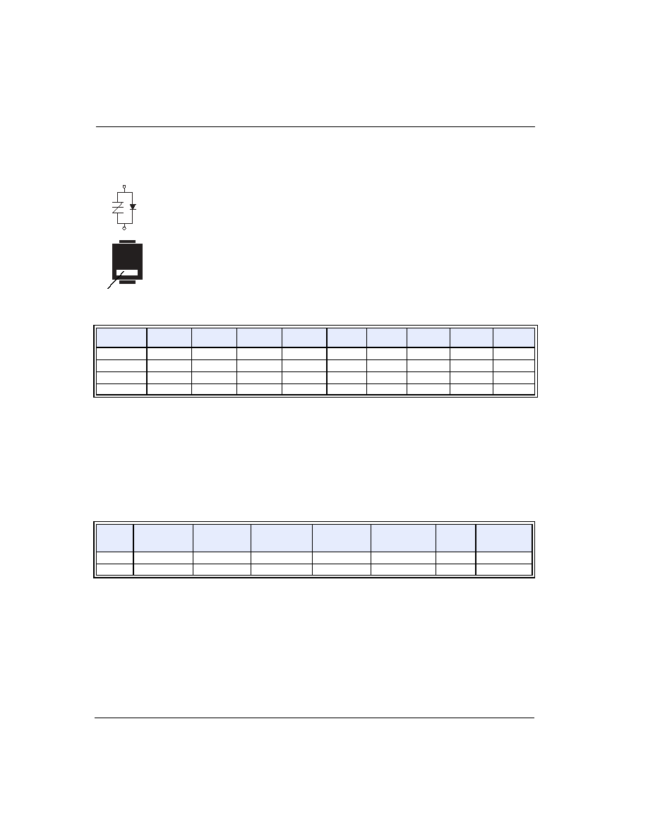
These DO-214AA unidirectional protectors are constructed with a SIDACtor device and an
integrated diode. They protect SLICs (Subscriber Line Interface Circuits) from damage
during transient voltage activity and enable line cards to meet various regulatory
requirements including GR 1089, ITU K.20, K.21 and K.45, IEC 60950, UL 60950, and TIA-
968 (formerly known as FCC Part 68).
For specific design criteria, see details in Figure 3.23.
* For individual "SA" and "SC" surge ratings, see table below.
General Notes:
∑ All measurements are made at an ambient temperature of 25 ∞C. I
PP
applies to -40 ∞C through +85 ∞C temperature range.
∑ I
PP
is a repetitive surge rating and is guaranteed for the life of the product.
∑ V
DRM
is measured at I
DRM.
∑ V
S
and V
F
are measured at 100 V/µs.
∑ Special voltage (V
S
and V
DRM
) and holding current (I
H
) requirements are available upon request.
∑ Off-state capacitance is measured at 1 MHz with a 2 V bias and is a typical value for "SA" and "SB" product. "SC" capacitance is
approximately 2x the listed value.
∑ Parallel capacitive loads may affect electrical parameters.
Electrical Parameters
Part
Number *
V
DRM
Volts
V
S
Volts
V
T
Volts
V
F
Volts
I
DRM
µAmps
I
S
mAmps
I
T
Amps
I
H
mAmps
C
O
pF
P0641S_
58
77
4
5
5
800
1
120
70
P0721S_
65
88
4
5
5
800
1
120
70
P0901S_
75
98
4
5
5
800
1
120
70
P1101S_
95
130
4
5
5
800
1
120
70
Surge Ratings (Preliminary Data)
Series
I
PP
2x10 µs
Amps
I
PP
8x20 µs
Amps
I
PP
10x160 µs
Amps
I
PP
10x560 µs
Amps
I
PP
10x1000 µs
Amps
I
TSM
60 Hz
Amps
di/dt
Amps/µs
A
150
150
90
50
45
20
500
C
500
400
200
150
100
50
500
(T/R)
(G)
Cathode
Fixed Voltage SLIC Protector
© 2003 Teccor Electronics
2 - 53
http://www.teccor.com
SIDACtor
Æ
Data Book and Design Guide
+1 972-580-7777
D
a
ta
S
h
e
e
ts
Thermal Considerations
Package
Symbol
Parameter
Value
Unit
DO-214AA
T
J
Operating Junction Temperature Range
-40 to +150
∞C
T
S
Storage Temperature Range
-65 to +150
∞C
R
JA
Thermal Resistance: Junction to Ambient
90
∞C/W
I
H
I
T
I
S
I
DRM
V
DRM
V
T
+V
-V
+I
-I
V
S
I
H
I
DRM
V
DRM
V
T
+V
+I
V
S
I
S
I
T
V
F
-V
-I
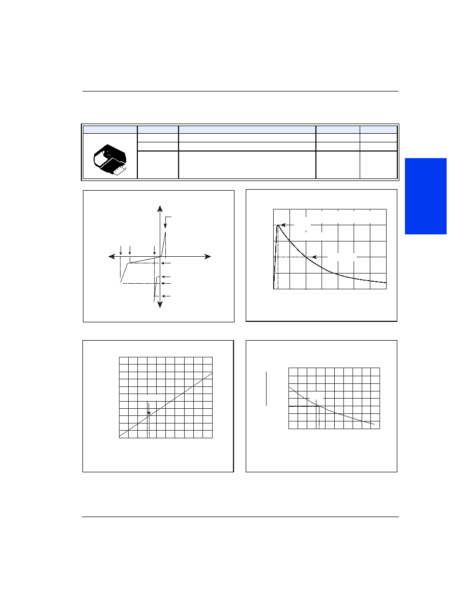
V-I Characteristics
50
100
0
t
r
t
d
0
Peak
Value
Half Value
t ≠ Time (µs)
I
PP
≠ P
e
ak Pulse Current ≠ %I
PP
t
r
= rise time to peak value
t
d
= decay time to half value
Waveform = t
r
x t
d
t
r
x t
d
Pulse Wave-form
-8
-40 -20
0
20
40 60
80 100 120 140 160
-6
-4
0
2
4
6
8
10
12
14
Junction Temperature (T
J
) ≠ ∞C
P
ercent of
V
S
Change ≠ %
25 ∞C
Normalized V
S
Change versus Junction Temperature
0.4
-40 -20
0
20 40 60 80 100 120 140 160
0.6
0.8
1.0
1.2
1.4
1.6
1.8
2.0
Case Temperature (T
C
) ≠ ∞C
Ratio of
I
H
I
H
(T
C
= 25 ∞C)
25 ∞C
Normalized DC Holding Current versus Case Temperature