
2-11
TELCOM SEMICONDUCTOR, INC.
7
6
5
4
3
1
2
8
TC07
TC07-1 9/18/96
ORDERING INFORMATION
Part No.
Package
Temp. Range
TC07COA
8-Pin SOIC
0
�
C to +70
�
C
TC07CUA
8-Pin MSOP
0
�
C to +70
�
C
TC07EOA
8-Pin SOIC
� 40
�
C to +85
�
C
TC07EUA
8-Pin MSOP
� 40
�
C to +85
�
C
TC07VOA
8-Pin SOIC
� 40
�
C to +125
�
C
TC07VUA
8-Pin MSOP � 40
�
C to +125
�
C
FUNCTIONAL BLOCK DIAGRAM
3V LOGIC OUTPUT TEMPERATURE SENSOR WITH
PROGRAMMABLE HYSTERESIS
FEATURES
s
User Programmable Hysteresis and Temperature
Set Point
s
Easily Programs with Two External Resistors
s
Wide Temperature Detection Range
TC07CxA ....................................... 0
�
C to +70
�
C
TC07ExA ................................ � 40
�
C to +85
�
C
TC07VxA ............................... � 40
�
C to +125
�
C
s
Small 8-Pin MSOP and 8-Pin SOIC Packages
s
Cost Effective
APPLICATIONS
s
Power Supply Over-Temperature Detection
s
Consumer Equipment
s
Temperature Regulators
s
Computer Equipment
GENERAL DESCRIPTION
The TC07 is a programmable, logic output temperature
detector that operates from power supply levels as low as
2.7V. Programming is accomplished with external resistors
connected from the temperature setpoint input (T
SET
) and
the hysteresis control input (H
SET
) to V
DD
.
Complimentary outputs (OUT and OUT) are driven
active when temperature exceeds the temperature thresh-
old programmed by the resistor on T
SET
. The states of these
outputs are maintained (latched) until temperature falls
below threshold programmed by the resistor on H
SET
.
The TC07 is useful over a maximum temperature range
of � 40
�
C to +125
�
C (TC07VxA). It features low (<130
�
A)
supply current and small physical size 8-pin MSOP and
8-pin SOIC packages, making it suitable for a wide variety
of applications.
PIN CONFIGURATION
8-Pin MSOP
T
SET
OUT
OUT
TEMPERATURE
TO VOLTAGE
CONVERTER
VOLTAGE
REFERENCE
GENERATOR
TEMP
SENSOR
H
SET
V
DD
GND
+
+
�
�
S Q
R Q
8-Pin SOIC
GND
TSET
HSET
NC
GND
TSET
HSET
NC
VDD
OUT
OUT
NC
VDD
OUT
OUT
NC
8
7
6
5
1
2
3
4
1
8
2
7
3
6
4
5
TC07COA
TC07EOA
TC07VOA
TC07CUA
TC07EUA
TC07VUA

2-12
TELCOM SEMICONDUCTOR, INC.
* Stresses above those listed under "Absolute Maximum Ratings" may
cause permanent damage to the device. These are stress ratings only and
functional operation of the device at these or any other conditions above
those indicated in the operation sections of the specifications is not implied.
Exposure to absolute maximum rating conditions for extended periods may
affect device reliability.
ABSOLUTE MAXIMUM RATINGS*
Supply Voltage .............................................................. 7V
Input Voltage Any Input ...... (GND � 0.3V) to (V
DD
+ 0.3V)
Operating Temperature ......................... � 40
�
C to +125
�
C
Maximum Chip Temperature ................................. +150
�
C
Storage Temperature ............................ � 65
�
C to +150
�
C
Lead Temperature (Soldering, 10 sec) ................. +300
�
C
DETAILED DESCRIPTION
The TC07 programs with resistors connected from the
T
SET
and H
SET
inputs to V
DD
. Output pins OUT and OUT are
driven active when temperature exceeds the setting deter-
mined by the programming resistor on T
SET
. The outputs are
maintained (latched) in their active states until temperature
drops below the setting determined by the programming
resistor on H
SET
(Figure 1).
Figure 1. TC07 Output Waveforms
TEMPERATURE
OUT
TEMPERATURE SET BY
RESISTOR ON T
SET
HYSTERESIS SET BY
RESISTOR ON H
SET
OUT
APPLICATIONS
Trip Point Programming
The resistor values required to achieve the desired
trip-point temperatures on T
SET
and H
SET
are calculated
using the formula below:
R
TRIP
= 0.6 x T
2.13
Where:
R
TRIP
= Programming resistor value in Ohms
T
= Desired trip point temperature in degrees
Kelvin.
For example, to program the TC07 outputs to go active
at 50
�
C and inactive at 30
�
C, the T
SET
and H
SET
program-
ming resistors are calculated as follows:
T
SET
= 0.6 x ((50 + 273.15)
2.13
) = 132.8k
H
SET
= 0.6 x ((30 + 273.15)
2.13
) = 115.9k
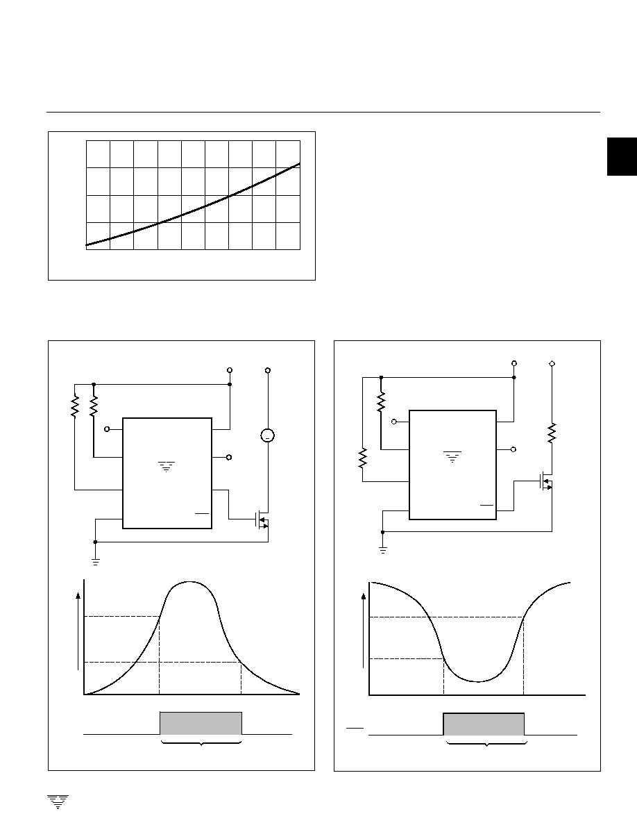
Resistance values for T
SET
and H
SET
can be approxi-
mated using Figure 2. Care must be taken to ensure the
H
SET
programming resistor is a smaller value than the T
SET
programming resistor. The temperature programmed on
H
SET
must be at least 5
�
C lower than the temperature value
programmed by T
SET
. That is: H
SET
T
SET
� 5
�
C.
ELECTRICAL CHARACTERISTICS:
T
A
= Over Operational Temperature Range, unless otherwise specified.
Symbol
Parameter
Conditions
Min
Typ
Max
Unit
V
DD
Supply Voltage Range
2.7
--
5.5
V
I
DD
Supply Current
2.7V < V
CC
< 5.5V
--
130
300
�
A
V
OH
Output Voltage (High)
I
OUT
= 500
�
A
0.8 x V
DD
--
--
V
V
OL
Output Voltage (Low)
I
OUT
= 1mA
--
--
0.25 x V
DD
V
H
Minimum Hysteresis
H
SET
< T
SET
� 5
--
--
�
C
T
SET
Absolute Accuracy
T = Programmed Temperature
T � 3
T
�
1
T + 3
�
C
H
SET
Absolute Accuracy
T = Programmed Temperature
T � 5
T
�
1
T + 5
�
C
TC07
3V LOGIC OUTPUT TEMPERATURE
SENSOR WITH PROGRAMMABLE
HYSTERESIS
2-13
TELCOM SEMICONDUCTOR, INC.
7
6
5
4
3
1
2
8
TEMPERATURE (
�
C)
RESISTANCE (k
)
-55
-35
-15
5
25
45
65
85
105
125
50
100
150
200
250
Figure 2. Programming Resistor Values vs. Temperature
Figure 3. TC07 as a Fan Controller
NC
TC07
R
T
R
H
+2.7 to 5.5V
+12V
T
SET
H
SET
GND
V
DD
OUT
NC
LOGIC
LEVEL
MOSFET
DC FAN
OUT
+
TEMPERATURE
OUT
FAN "ON"
H
SET
T
SET
Figure 4. TC07 as a Heater Thermostat
NC
TC07
R
T
R
H
+2.7 to 5.5V
+12V
T
SET
H
SET
GND
V
DD
OUT
NC
LOGIC
LEVEL
MOSFET
HEATER
OUT
TEMPERATURE
OUT
HEATER "ON"
H
SET
T
SET
Cooling and Heating Applications
The TC07 can be used to control a DC fan as shown in
Figure 3. The fan turns on when the sensed temperature
rises above T
SET
and remains on until the temperature falls
below H
SET
. The amount of "over-cooling" performed by the
fan is dependent on the programmed hysteresis.
Figure 4 shows the TC07 acting as a heater thermostat.
Circuit operation is identical to that of the cooling fan
application.
TC07
3V LOGIC OUTPUT TEMPERATURE
SENSOR WITH PROGRAMMABLE
HYSTERESIS