 | –≠–ª–µ–∫—Ç—Ä–æ–Ω–Ω—ã–π –∫–æ–º–ø–æ–Ω–µ–Ω—Ç: BZT55C56 | –°–∫–∞—á–∞—Ç—å:  PDF PDF  ZIP ZIP |

TELEFUNKEN Semiconductors
BZT55C...
1
Rev. A1: 12.12.1994
Silicon Epitaxial Planar Z≠Diodes
Features
D Very sharp reverse characteristic
D Low reverse current level
D Very high stability
D Low noise
D Available with tighter tolerances
Applications
Voltage stabilization
94 9373
Absolute Maximum Ratings
T
j
= 25
_C
Parameter
Test Conditions
Type
Symbol
Value
Unit
Power dissipation
R
thJA
x300K/W
P
V
500
mW
Z≠current
I
Z
P
V
/V
Z
mA
Junction temperature
T
j
175
∞C
Storage temperature range
T
stg
≠65...+175
∞C
Maximum Thermal Resistance
T
j
= 25
_C
Parameter
Test Conditions
Symbol
Value
Unit
Junction ambient
on PC board 50mmx50mmx1.6mm
R
thJA
500
K/W
Characteristics
T
j
= 25
_C
Parameter
Test Conditions
Type
Symbol
Min
Typ
Max
Unit
Forward voltage
I
F
=200mA
V
F
1.5
V

TELEFUNKEN Semiconductors
BZT55C...
2
Rev. A1: 12.12.1994
Type
V
Znorm
I
ZT
for V
ZT
1)
and r
zjT
r
zjk
at I
ZK
I
R
and I
R
2)
at
V
R
TK
VZ
BZT55C...
V
mA
V
W
W
mA
mA
mA
V
%/K
2 V 4
2.4
5
2.28 to 2.56
< 85
< 600
1
< 100
< 50
1
≠0.09 to ≠0.06
2 V 7
2.7
5
2.5 to 2.9
< 85
< 600
1
< 10
< 50
1
≠0.09 to ≠0.06
3 V 0
3.0
5
2.8 to 3.2
< 90
< 600
1
< 4
< 40
1
≠0.08 to ≠0.05
3 V 3
3.3
5
3.1 to 3.5
< 90
< 600
1
< 2
< 40
1
≠0.08 to ≠0.05
3 V 6
3.6
5
3.4 to 3.8
< 90
< 600
1
< 2
< 40
1
≠0.08 to ≠0.05
3 V 9
3.9
5
3.7 to 4.1
< 90
< 600
1
< 2
< 40
1
≠0.08 to ≠0.05
4 V 3
4.3
5
4.0 to 4.6
< 90
< 600
1
< 1
< 20
1
≠0.06 to ≠0.03
4 V 7
4.7
5
4.4 to 5.0
< 80
< 600
1
< 0.5
< 10
1
≠0.05 to +0.02
5 V 1
5.1
5
4.8 to 5.4
< 60
< 550
1
< 0.1
< 2
1
≠0.02 to +0.02
5 V 6
5.6
5
5.2 to 6.0
< 40
< 450
1
< 0.1
< 2
1
≠0.05 to +0,05
6 V 2
6.2
5
5.8 to 6.6
< 10
< 200
1
< 0.1
< 2
2
0.03 to 0.06
6 V 8
6.8
5
6.4 to 7.2
< 8
< 150
1
< 0.1
< 2
3
0.03 to 0.07
7 V 5
7.5
5
7.0 to 7.9
< 7
< 50
1
< 0.1
< 2
5
0.03 to 0.07
8 V 2
8.2
5
7.7 to 8.7
< 7
< 50
1
< 0.1
< 2
6.2
0.03 to 0.08
9 V 1
9.1
5
8.5 to 9.6
< 10
< 50
1
< 0.1
< 2
6.8
0.03 to 0.09
10
10
5
9.4 to 10.6
< 15
< 70
1
< 0.1
< 2
7.5
0.03 to 0.1
11
11
5
10.4 to 11.6
< 20
< 70
1
< 0.1
< 2
8.2
0.03 to 0.11
12
12
5
11.4 to 12.7
< 20
< 90
1
< 0.1
< 2
9.1
0.03 to 0.11
13
13
5
12.4 to 14.1
< 26
< 110
1
< 0.1
< 2
10
0.03 to 0.11
15
15
5
13.8 to 15.6
< 30
< 110
1
< 0.1
< 2
11
0.03 to 0.11
16
16
5
15.3 to 17.1
< 40
< 170
1
< 0.1
< 2
12
0.03 to 0.11
18
18
5
16.8 to 19.1
< 50
< 170
1
< 0.1
< 2
13
0.03 to 0.11
20
20
5
18.8 to 21.2
< 55
< 220
1
< 0.1
< 2
15
0.03 to 0.11
22
22
5
20.8 to 23.3
< 55
< 220
1
< 0.1
< 2
16
0.04 to 0.12
24
24
5
22.8 to 25.6
< 80
< 220
1
< 0.1
< 2
18
0.04 to 0.12
27
27
5
25.1 to 28.9
< 80
< 220
1
< 0.1
< 2
20
0.04 to 0.12
30
30
5
28 to 32
< 80
< 220
1
< 0.1
< 2
22
0.04 to 0.12
33
33
5
31 to 35
< 80
< 220
1
< 0.1
< 2
24
0.04 to 0.12
36
36
5
34 to 38
< 80
< 220
1
< 0.1
< 2
27
0.04 to 0.12
39
39
2.5
37 to 41
< 90
< 500
1
< 0.1
< 5
30
0.04 to 0.12
43
43
2.5
40 to 46
< 90
< 600
0.5
< 0.1
< 5
33
0.04 to 0.12
47
47
2.5
44 to 50
< 110
< 700
0.5
< 0.1
< 5
36
0.04 to 0.12
51
51
2.5
48 to 54
< 125
< 700
0.5
< 0.1
< 10
39
0.04 to 0.12
56
56
2.5
52 to 60
< 135
< 1000
0.5
< 0.1
< 10
43
0.04 to 0.12
62
62
2.5
58 to 66
< 150
< 1000
0.5
< 0.1
< 10
47
0.04 to 0.12
68
68
2.5
64 to 72
< 200
< 1000
0.5
< 0.1
< 10
51
0.04 to 0.12
75
75
2.5
70 to 79
< 250
< 1500
0.5
< 0.1
< 10
56
0.04 to 0.12
1)
t
p
/T
100 ms, tighter tolerances available on request.
2)
at T
j
= 150
∞
C
TELEFUNKEN Semiconductors
BZT55C...
3
Rev. A1: 12.12.1994
Typical Characteristics (T
j
= 25
_C unless otherwise specified)
0
40
80
120
160
0
100
300
400
500
600
P
≠
T
otal Power Dissipation ( mW
)
tot
T
amb
≠ Ambient Temperature (
∞
C )
200
95 9602
200
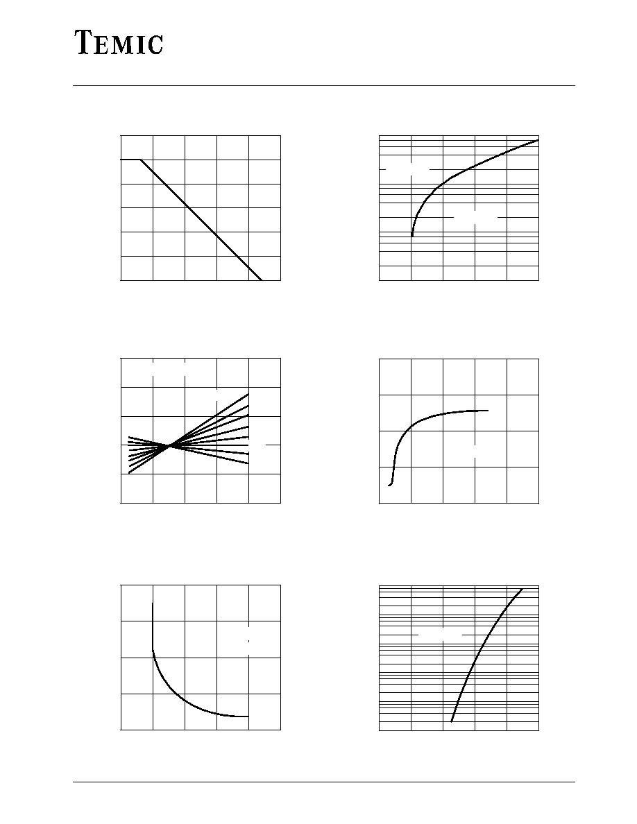
Figure 1 : Total Power Dissipation vs. Ambient Temperature
≠60
0
60
120
180
0.8
0.9
1.0
1.1
1.2
1.3
V
≠ Relative
V
oltage
Change
Ztn
T
j
≠ Junction Temperature (
∞
C )
240
95 9599
V
Ztn
=V
Zt
/V
Z
(25
∞
C)
TK
VZ
=10
10
≠4
/K
8
10
≠4
/K
≠4
10
≠4
/K
6
10
≠4
/K
4
10
≠4
/K
2
10
≠4
/K
≠2
10
≠4
/K
0
Figure 3 : Typical Change of Working Voltage vs. Junction
Temperature
0
5
10
15
0
50
100
150
200
C ≠ Diode Capacitance ( pF )
D
V
Z
≠ Z-Voltage ( V )
25
95 9601
20
T
j
= 25
∞
C
V
R
= 2V
Figure 5 : Diode Capacitance vs. Z≠Voltage
0
5
10
15
20
1
10
100
1000
V
≠
V
oltage
Change
(
mV
)
Z
V
Z
≠ Z-Voltage ( V )
25
95 9598
D
I
Z
=5mA
T
j
= 25
∞
C
Figure 2 : Typical Change of Working Voltage under Operating
Conditions at Tamb=25∞C
0
10
20
30
≠5
0
5
10
15
TK ≠
T
emperature
Coef
ficient of
V
( 10 /K )
VZ
V
Z
≠ Z-Voltage ( V )
50
95 9600
40
Z
≠4
I
Z
=5mA
Figure 4 : Temperature Coefficient of Vz vs. Z≠Voltage
0
0.2
0.4
0.6
0.8
0.001
0.01
0.1
1
10
100
1.0
95 9605
I ≠ Forward Current ( mA
)
F
V
F
≠ Forward Voltage ( V )
T
j
= 25
∞
C
Figure 6 : Forward Current vs. Forward Voltage
TELEFUNKEN Semiconductors
BZT55C...
4
Rev. A1: 12.12.1994
0
4
8
12
16
20
95 9604
0
20
40
60
80
100
I ≠ Z-Current ( mA
)
Z
V
Z
≠ Z-Voltage ( V )
P
tot
=500mW
T
amb
=25
∞
C
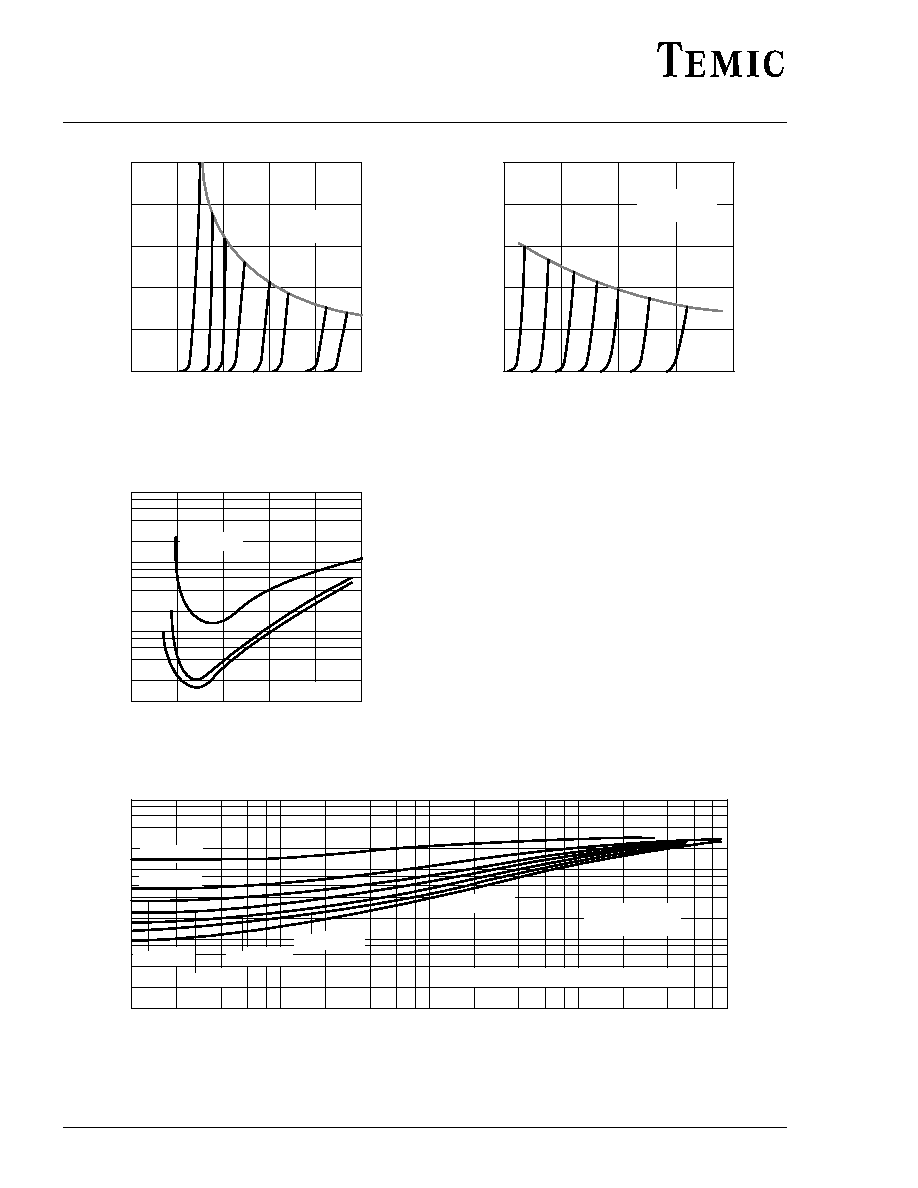
Figure 7 : Z≠Current vs. Z≠Voltage
0
5
10
15
20
1
10
100
1000
r ≠ Dif
ferential Z-Resistance ( )
Z
V
Z
≠ Z-Voltage ( V )
25
95 9606
W
T
j
= 25
∞
C
I
Z
=1mA
5mA
10mA
Figure 9 : Differential Z≠Resistance vs. Z≠Voltage
15
20
25
30
0
10
20
30
40
50
I ≠ Z-Current ( mA
)
Z
V
Z
≠ Z-Voltage ( V )
35
95 9607
P
tot
=500mW
T
amb
=25
∞
C
Figure 8 : Z≠Current vs. Z≠Voltage
1
10
100
1000
Z ≠
Thermal Resistance for Pulse Cond. (K/W)
thp
t
p
≠ Pulse Length ( ms )
95 9603
10
≠1
10
0
10
1
10
2
t
p
/T=0.5
t
p
/T=0.2
t
p
/T=0.1
t
p
/T=0.05
t
p
/T=0.02
t
p
/T=0.01
Single Pulse
R
thJA
=300K/W
DT=T
jmax
≠T
amb
i
ZM
=(≠V
Z
+(V
Z
2
+4r
zj
DT/Z
thp
)
1/2
)/(2r
zj
)
Figure 10 : Thermal Response

TELEFUNKEN Semiconductors
BZT55C...
5
Rev. A1: 12.12.1994
Dimensions in mm
Cathode Identification
V 1.5
1.3
94 9372
0.35
0.30
0.35
0.30
3.7
3.3
technical drawings
according to DIN
specifications
Quadro MELF
Glass Case similar to
JEDEC DO 213 AA