
U4074B
Preliminary Information
TELEFUNKEN Semiconductors
Rev. A1, 06-May-96
1 (6)
Tone Ringer Interface
Description
The U4074B is a monolithic integrated circuit that
contains all integral components of a ringing circuit for
telephone sets used in conjunction with a microcomputer.
The combination of a microcomputer and the U4074B
permits flexible programming of the ringing sequence
( melody ), tone and volume control.
Ringing frequency detection takes place in the
microcomputer. The U4074B is responsible for the
interface to the line, driver stages for the piezoelectric
sound transducer, volume adjustment, amplitude
detection, voltage supply for the microcomputer and
other auxiliary functions.
Features
D Suitable for specifications FTZ 1TR2 and ETR 2
D Rectifier bridge
D Z-diode
D Amplitude detection
D Supply voltage for microcomputer 3.5 @ v 1.5 mA
D DC operation possible
D Bridge push-pull output stage
D CMOS-compatible microcomputer interface
D 2-bit log. volume adjustment
D High-voltage bipolar technology, 30 V
Benefits
D mC controlled melody and volume
D Low number of external components
Control
VRef
Decoder and
DA converter
TH
10 (12)
2f
3(4)
4(5)
VDD
130 k
47 F
22 F
2(3)
VB
(1)1
(16)14
+VB
+VB
12(14)
11(13)
O2
O1
PIEZO
Transducer
(15)13 GND 5(6)
6(7) (9)7 Mel
A1
A0
Volume
DC
V
8(10)
9(11)
0.8 F
2.2 k
a
b
Ringing signal
93 7793 e
On/Off
2f
W
m
m
W
m
a
b
Figure 1. Block diagram and application circuit ( pin connections for SO16 in brackets )

U4074B
TELEFUNKEN Semiconductors
Rev. A1, 06-May-96
Preliminary Information
2 (6)
Pin Configuration
14
13
12
11
10
9
8
1
2
3
4
5
6
7
16
15
94 7904 e
NC
TH
2f
A1
A0
DD
GND
O2
O1
V
Mel
NC
VB
DC
V
DC
V
a
b
14
13
12
11
10
9
8
1
2
3
4
5
6
7
V
TH
2f
A1
A0
Mel
V
GND
O2
O1
B
DC
VDC
VDD
94 7903 e
a
b
Pin
Symbol
Function
1, 14
(1,16)
a , b
AC ringing signal input
2 (3)
V
B
Output to charging capacitor
3 (4)
TH
Comparator threshold adjust-
ment input
4 (5)
2f
Output for frequency detection
5, 6
(6, 7)
A1, A0
Digital volume adjustment in-
put
7 (9)
Mel
Input for melody signal
8, 9
(10, 11)
V
DC
DC supply diode connections
10 (12)
V
DD
Microcomputer supply voltage
11, 12
(13, 14)
O
1
, O
2
Outputs to the transducer
13 (15)
GND
Ground
(2, 8)
NC
Not connected
Pin Description
Power supply a and b , Pin 1, 14
An ac ringing voltage is supplied to the inputs a and b
via a 0.8
mF decoupling capacitor connected in series with
a
2.2 k
. resistor
3.
The circuit possesses the following overload resis-
tance at terminals a and b.The circuit can withstand
a voltage of 110 V with a frequency of 50 Hz at
terminals a and b for a maximum of 15 s.
4.
Testing the circuit with the configuration shown in
figure 2 does not destroy the circuit under the
following conditions.
Charging voltage of surge capacitance: V
cs
= 2 kV
Pulse shape: 10/700
ms
Pulse sequence: 30 s
Number of surges: 10
Polarity change after 5 surges
See figure 2.
Smoothing Capacitors, Pin 2, 10
After rectification of the ac ringing voltage via the
integrated rectifier bridge, the pulsating DC voltage is
smoothed by the external capacitor ( 22
mF to 47 mF) at
Pin
2
( 3 ). The charging voltage is restricted to a
maximum of 30 V by an integrated Z-diode. A 47
mF
external capacitor of will smooth the regulated supply,
V
DD
, at pin 10 (12 ).

U4074B
Preliminary Information
TELEFUNKEN Semiconductors
Rev. A1, 06-May-96
3 (6)
Tone ringing
Figure 1
2 kV
93 7575 e
a
b
10
mF
110
0.22
mF
15
25
W
W
W
Figure 2. Test circuit
Outputs O
1
, O
2
Pin 11, 12
The bridge push-pull outputs are used for direct
connection of a piezo electric sound transducer with a
typical value of 80 nF. The output stage transistors can
process up to 20 mA in both directions.
The output signal without load is 2
(V
B
- V
DD
� 3.5 V)
R
i
+
V
(12,11
open
V
(12,11)
load
� 1
R
load
where R
load
= 400
W
Volume Adjustment A1, A0
Pin 5 (6), 6 (7)
The ringing volume is adjusted by means of a 2-bit D/A
converter. The maximum volume is achieved with the bit
combination A1 (MSB) = 1 and A0 (LSB) = 1. The
volume can be reduced by approximately 35 dB (A) if a
bit combination of A1 = 0, A0 = 0 is
supplied. The volume
is programmed by supplying a ground potential to these
inputs.
Melody, Pin 7 (9)
The melody input inverts the activation phase of the
bridge push-pull output stage. The input is CMOS-
compatible and suitable for processing ringing
frequencies.
Supply Voltage V
DD,
Pin 10 (12)
An external load, such as a microcomputer, can be
connected to V
DD
. This value of V
DD
is 3.5 V for a
maximum load current of 1.5 mA. V
DD
is highly resistive
and can block up to 6 V in call and idle states. The typical
value of the back-up capacitor is 47
mF.
Frequency Detection 2f, Pin 4 (5)
Frequency detection takes place in the microcomputer.
For this purpose, the output 2f supplies a square wave
signal with double ringing frequency to the
microcomputer. The output signal is CMOS-compatible.
This terminal is highly resistive in idle and call states.
Comparator Threshold Adjustment
TH Pin 3 (4)
The on/ off threshold of the 2f comparator can be adjusted
( terminal against ground respectively V
DD
). To fulfill the
Bundespost specification this terminal should be open.
V
DC,
Pin 8, 9
Decoupling diode for dc supply.
U4074B
TELEFUNKEN Semiconductors
Rev. A1, 06-May-96
Preliminary Information
4 (6)
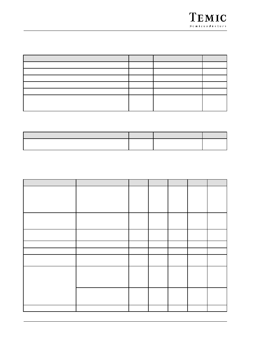
Absolute Maximum Ratings
Reference point, Pin 13 ( 15 ), unless otherwise specified, T
amb
= 25
�
C
Parameters
Symbol
Value
Unit
Supply current
Pin 1, 14 ( 1, 16 )
I
s
50
mA
Output current
Pin 11, 12 ( 13, 14 )
I
0
50
mA
Junction Temperature
T
j
125
�
C
Ambient temperature
T
amb
�25 to + 60
�
C
Storage temperature
T
stg
�40 to + 125
�
C
Power dissipation
T
amb
= 60
�
C
DIP14
SO16
P
tot
P
tot
860
400
mW
mW
Thermal Resistances
Parameters
Symbol
Value
Unit
Junction ambient
DIP14
SO16
R
thJA
75
160
K/W
K/W
Electrical Characteristics
T
amb
= �10 to 60
�
C, reference point is Pin 13 ( 15 ), unless otherwise specified
Parameters
Test Conditions / Pins
Symbol
Min.
Typ.
Max.
Unit
Current consumption
Pin 1, 14 (1, 16)
O
1
= O
2
= open
A1 = A0 = 0, V
B
= 15 V
I
DD
= �300
mA,
Pin 2 (3) open
I
1.1
1.4
mA
Input voltage
Pin 1, 14 (1, 16)
on threshold
off threshold
V
9.5
4.5
10.5
5.5
11.5
6.5
V
V
Audio frequency
impedance
f = 300 to 3400 Hz,
V
a,b
= 1.5 V
rms
R
200
k
W
Output on resistance
I
(O1, O2)
=
"20 mA
R
on
400
W
Internal voltage limitation
I
Z
= 1 mA (Pin 2)
V
Z
25
27
30
V
Supply voltage for
microcomputer
0.5 mA > I
DD
< 1.5 mA
3.15
3.5
3.85
V
Leakage current
V
a
, V
b
, V
B
v 3.5 V
I
2f
I
A0
I
A1
I
10
mA
V
A1
, V
A0
, V
Melody
v 6 V
5.5 V
v V
DD
v 6 V
0 V
v V
DD
v 5.5 V
I
DD
100
10
mA
Diode load current
80
mA

U4074B
Preliminary Information
TELEFUNKEN Semiconductors
Rev. A1, 06-May-96
5 (6)
Order Information
Extended Type Number
Package
Remarks
U4070B-FP
SO16
U4074B
DIP14
Dimensions in mm
Package: DIP14
Package: SO16