
THAT Corporation; 734 Forest Street; Marlborough, Massachusetts 01752; USA
Tel: (508) 229-2500; Fax: (508) 229-2590; Web: http://www.thatcorp.com
-
+
47p
4k99
3k57
OUT
OP275
IN
NC
2
1
7
6
5
4
3
INPUT
CONTROL
OUT
IN
-15V
+15V
22uf
V+
V-
Ec
SYM
GND
2002
Figure 1. 2002 Typical Application Circuit
N/C
.20
.48
OUT
EC
V-
V+
GND
IN
.40
.13
2.06
1.80
1.30
.13
BOTTOM
VIEW
.040 DIA. TYP.
.80
1.06
Figure 2. 2002 Physical Outline
dbx is a registered trademark of Carillon Electronics Corporation
FEATURES
�
Wide Dynamic Range: >130 dB
�
Wide Gain Range: > 130 dB
�
Logarithmic Gain Control
�
Very Low Distortion: (0.004%
@0 dB gain, 0.01% @20dB gain)
�
Temperature Compensated
(2002T)
�
Package Compatible with dbx 202
APPLICATIONS
�
Faders
�
Console Automation
�
Panners
�
Compressors
�
Expanders
�
Filters
�
Oscillators
Description
The THAT 2002N, 2002T and 2002R modular
voltage-controlled amplifiers (VCAs) represent the
highest state of the current VCA art. They are ex-
tremely high performance current-in/ current-out
devices with negative-sense control ports. Intended
for the most demanding of applications, these parts
require almost no external support circuitry and
are packaged in small, 1" X 2"X0.5" modules. Their
pin configurations are identical to that of the origi-
nal dbx 202 VCA, as well as later dbx models 202C,
202X, 202XL and 2001, and THAT models 202XT,
202XTC and 202R.
The 2002T has a control
constant of
�20dB/Volt, and is internally temperature compen-
sated for very low thermal drift. The 2002T is rec-
ommended for all new designs. The 2002N is
intended to replace earlier dbx or THAT models in
designs where control-voltage temperature compen-
sation was provided externally. Like most dbx and
THAT modular VCAs, the 2002N has a control con-
stant of �20dB/Volt, with a predictable +0.33%/�C
temperature drift. The 2002R is intended to re-
place the original dbx 202. The 2002R matches the
dbx 202's control sensitivity of �6mV/dB and its
predictable +0.33%/�C temperature drift
THAT
2002N, 2002T, 2002R
T H A T
C o r p o r a t i o n
Modular Voltage-Controlled
Amplifiers
THAT Corporation; 734 Forest Street; Marlborough, Massachusetts 01752; USA
Tel: (508) 229-2500; Fax: (508) 229-2590; Web: http://www.thatcorp.com
Page 2
2002-Series Modular VCAs
1. All specifications subject to change without notice.
2. Unless otherwise noted, T
A
=25�C, V
CC
= +15V, V
EE
= -15V. Test circuit is as shown in Figure 1.
SPECIFICATIONS
1
Absolute -Maximum Ratings (T
A
= 25�C)
Positive Supply Voltage (V
CC
)
+20 V
Negative Supply Voltage (V
EE
)
-20 V
Supply Current (I
CC
)
30 mA
Power Dissipation (P
D
)
1 W
Operating Temperature Range (T
OP
)
-20 to +60�C
Storage Temperature Range (T
ST
)
-40 to +125�C
Recommended Operating Conditions
2002N
2002R
2002T
Parameter
Symbol
Conditions
Min
Typ
Max
Min
Typ
Max
Min
Typ
Max
Units
Positive Supply Voltage
V
CC
+12
+15
+18
12
+15
+18
+12
+15
+18
V
Negative Supply Voltage
V
EE
12
-15
-18
-12
-15
-18
-12
-15
-18
V
Signal Current
V
CC
=-V
EE
=15 V
--
1.4
6.0
--
1.4
6.0
--
1.4
6.0
mA
Electrical Characteristics
2
2002N
2002R
2002T
Parameter
Symbol
Conditions
Min
Typ
Max
Min
Typ
Max
Min
Typ
Max
Units
Supply Current
I
CC
No Signal
--
18
26
--
18
26
--
18
26
mA
Input Impedance
R
IN
1.37
1.4
1.43
1.37
1.4
1.43
1.37
1.4
1.43
k
W
Equiv. Input Bias Current
I
B
No Signal
--
8
60
--
8
60
--
8
60
nA
Input Offset Voltage
V
OFF(IN)
No Signal
--
�5
--
--
�5
--
--
�5
--
mV
Output Offset Voltage
V
OFF(OUT)
R
out
=4.99 k
W
-100 dB < gain< 0 dB
--
1
2
--
1
2
--
1
2
mV
+20 dB gain
--
5
10
--
5
10
--
5
10
mV
Gain-Control Constant
dB gain/E
C
T
A
=27
�C
-100 dB< gain <+40 dB
19.3
20
20.7
161.0 166.7 172.6
19.3
20
20.7
dB/V
Gain-control TempCo
DGain/DT
A
0
�C<T
A
<70
�C
E
C
constant
--
-0.33
--
--
-0.33
--
-0.04
0.0
+0.04
%/
�C
Gain-Control Linearity
-60 to +40 dB gain
--
0.5
2
--
0.5
2
--
0.5
2
%
Off Isolation
E
C
= -6V
110
115
--
--
--
--
110
115
dB
E
C
= -.72V
--
--
--
110
115
--
dB
Output Noise
e
n(OUT)
20Hz-20kHz,R
out
= 4.99k
W
0 dB gain
--
-104
-102
--
-104
-102
--
-104
-102
dBV
+20 dB gain
--
-89
-87
--
-89
-87
--
-89
-87
dBV
Total Harmonic Distortion
THD
1kHz
0 dB gain, 0 dBV out
--
0.004
--
--
0.004
--
--
0.004
--
%
0 dB gain, +10 dBV out
--
0.006 0.01
--
0.006 0.01
--
0.006 0.01
%
+20 dB gain, +10 dBV out --
0.01
0.03
--
0.01
0.03
--
0.01
0.03
%
-20 dB gain, +10 dBV in
--
0.01
0.03
--
0.01
0.03
--
0.01
0.03
%
Control Port Impedance
Rc
Ta = 25�C
806
815
823
198
200
202
786
832
881
W

THAT Corporation; 734 Forest Street; Marlborough, Massachusetts 01752; USA
Tel: (508) 229-2500; Fax: (508) 229-2590; Web: http://www.thatcorp.com
Rev. 2/10/97
Page 3
Figure 3. 1kHz THD+Noise vs. Input Level, 0 dB Gain
Figure 4. 1kHz THD+Noise vs. Input Level, +20 dB
Gain
Figure 5. 1kHz THD+Noise vs. Input Level, -20 dB
Gain
Figure 6. Representative DC Offset vs. Gain
Figure 7. THD+Noise vs. Frequency, 0dB Gain,
+10dBV In
Figure 8. THD+Noise vs. Frequency, +20dB Gain,
-10dBV In
Figure 9. THD+Noise vs. Frequency, -20dB Gain,
+10dBV In
Figure 10. Frequency Response at Various Gains
Representative Performance Curves
2
THAT Corporation; 734 Forest Street; Marlborough, Massachusetts 01752; USA
Tel: (508) 229-2500; Fax: (508) 229-2590; Web: http://www.thatcorp.com
Page 4
2002-Series Modular VCAs
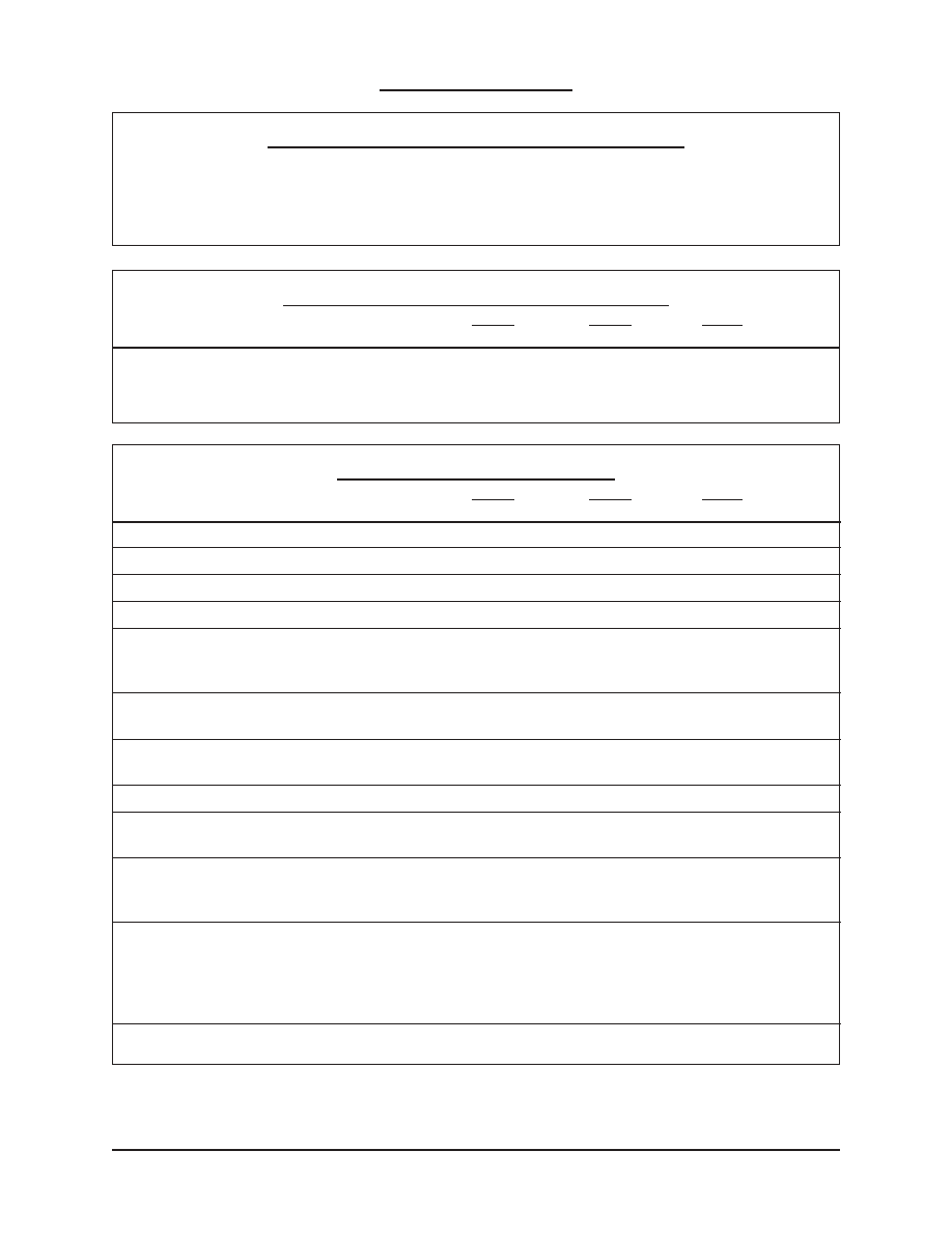
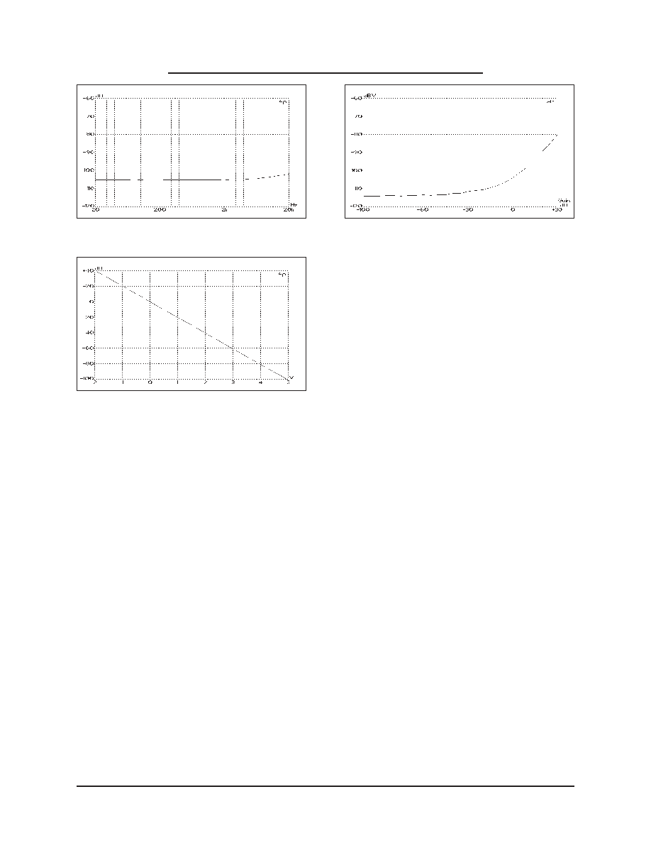
Figure 11. Off Isolation vs. Frequency, -105dB Gain
Figure 12. Gain vs. Control Voltage
Figure 13. Output Noise vs. Gain (20Hz~20kHz
Unweighted)
Representative Performance Curves
2
Cont'd